Back into the audio gear hobby

Hi all and thanks for the add to the forum.
I was pretty active with Japanese solid state audio gear in the mid-80s (military and stationed in Okinawa) but slowly drifted out of the hobby.
In the last four years, I started picking up vintage gear (US speakers and Japanese electronics) but have wanted to move over to a tube system as an experiment.
I was considering some McIntosh gear (I already have two sets of their speakers) but decided to build my own to see if I'm happy with the sound.
I've ordered an Elekit preamp kit and will get their TU-8900E when it's available.
I'm looking forward to re-engaging in the hobby and learning new things.
HAGO,
Todd

Greetings

Hi everyone! I’m happy to finally join this forum! I’ve been into DIY audio only for a short time (less than a year) but I’m in love. Already, I have gained a deeper understanding of the products that I use and can make much, much smarted decisions with my money!

I’ve built 3 Bottlehead kits and now a Sunvalley kit too. I’m hooked! I look forward to sharing my experiences with other forum members while taking my skills to the next level.

Cheers,

Sam

How to adapt a REL S510 from 120V to 240V mains

Hi,


Did not find this topic in the forum using search so setup a new topic on this issue.


I have a subwoofer amp for the US with a 120vac requirement and unfortunately, unlike I have done before, it does not have a transformer which can be swapped out as it uses an switching PSU.


I'm looking for a non transformer alternative do step down from 240vac to 110vac rated at 500w @ 240vac.


Any ideas?

Help is appreciated.

Cabinets, heat and gear stacking

So we all are aware that heat is the enemy.
WAF means that I need to make things look as neat and tidy as I can and to that end we bought a piece of furniture from IKEA.
So we have a 3 unit BESTA TV cabinet
BUT after assembly and using if for a while I realise it has very poor design for using as a multi unit cabinet even for our Mid-Fi system and I am going to need to remove all the components and modify it.
It's pretty enough for WAF but it simply doesn't have enough ventilation and it is far too shallow for a couple of the components I have.
I'd like some ideas from people here on ways to tackle this problem and still keep something acceptable to SWMBO.
Here's a link

BESTA TV bench with drawers - black-brown/Hanviken/Stubbarp black-brown clear glass - IKEA
Although ours is an earlier iteration it is similar and the same size. The television in our room is wall hung.
We have two turntables currently sitting on top although one will be going to the shed as soon as I tidy the shed up.
Home theatre amp. DVD Audio/SACD player, old VHS player because some movies are still on VHS and no digital copy exists as yet, Blue ray player Stereo pre-amp, Crossover, Rotel 1070 for mid-bass and an older 200 watt amplifier for bass duties. Plus the monoblocks sit next to the speakers
Quite a bit of heat generated at times

Crossing DX20BF00-08

Hello,

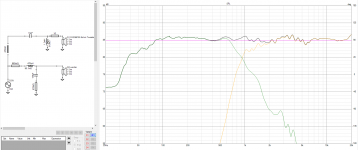
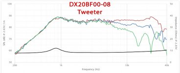
Been trying to crossover Peerless by Tymphany DX20BF00-08 and Dayton Audio DC160S-8 6-1/2" for quite some time now and below is the most flatish-response I could get out of them.

The question is, would crossing these drivers at around 930Hz be a problem? the frequency response graph of the tweeter seem to be ok starting 800?Hz which seem to be pretty low for a tweeter?

Also here is my final version of the crossover design, what would your constructive criticisms be?

Attachments

  • 1.jpg
    1.jpg
    52.1 KB · Views: 261
  • 2.png
    2.png
    82.7 KB · Views: 270

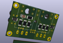
check my PCB please

Hi all,

I've put together this LM317/LM337 CRC filters based PCB to fit in a spot and replace a much simpler zener and pass transistor affair.

It's my first real attempt at putting together a PCB and paying attention to the layout. I've tried to keep the ground thick and straight, take the adjust pin resistors directly to the load output and place the output and adjust capacitors in the right places.

I have also tried to keep some sort of "flow", as it was put to me, in the power and ground traces.

Critiques and correction gratefully accepted. 🙂

Attachments

How close can speakers be to heat source ?

Hi All,

I was talking to a customer at work today and they asked me if their speakers would be ok when one was positioned approx 1.5 feet from a log burning stove.

I thought maybe the glues on the cones could be affected if they got hot, and suggested swapping left and right every couple of months to stop one from changing more than the other.

What do you guys think ? Maybe measure the temp on the side of the speaker and see if it's really a problem ?

Add some sort of heat shield ?

On a side note my TV speakers are 20" away from an open fire, with the brick side of the fireplace seperating them, and they've been fine for 6 years at least.

Thanks,
Rob.

Heat Sink Advice

I am building a pair of monoblocks approximately 11 (280mm) x 17 (430mm) x 3 (76mm) inches in size. I will be powder coating the outside of the chassis a dark hammertone green. I am hoping to heat sink the Coleman filament regulators to the chassis in one of two ways.
1) Mount them flat to the underside of the top plate with the outer surface powder coated. Or
2). Mount them on an aluminum bulkhead that will separate the power supply from the amplifier section. This will be 3 x 11 inches long. I would drill ventilation holes along both sides of that bulkhead to allow ventilation along with a mesh bottom plate. If I did that, is there an advantage to a thick plate vs a thin one?
I am concerned about the insulation of the powder coat if I use the top plate as compared to the less than ideal ventilation if utilizing the interior bulkhead.
Thoughts?

Mini Towers

Hello All,

It's been literally years since I posted here, but I thought I'd share my latest effort.

Disclaimer: still finishing the build - have not listened to them yet.

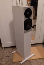
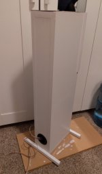
I call these the "AluMinis" after the driver diaphragm materials and the compact nature of the cabinet dimensions.

The basic goal was a simple yet modern-looking, small footprint, full-range 2-way speaker with high-value drivers. The cabinets are only about 5.5" wide, 32" tall and 10" deep; straight on they take up very little visual space. I used 1/2" mdf - in the future it will be 5/8"-3/4" - the 1/2" material is just too thin and flimsy, and prone to flaking.

This was my very first build using a (entry level) table saw and cutting a cabinet from scratch, and believe me, the flaws are there, but I'm still happy with the outcome - the overall look was exactly what I had in mind.

I actually cut the driver and port holes with hole cutters, and then used craft plywood for the driver "recesses," cutting them with a rotary tool and a Dremel adaptor that turns it into a tiny but still screaming plunge router. Yes - next time a real router.

Everything us just painted - three coats of hand-applied satin interior light grey latex (paint + primer), and the 3mm plywood pieces just rattle canned with a bit darker grey. Rather than trying to miter the seams I used iron-on white melamine edge banding, which though a bit tricky did a good job of adding some nice clean cosmetic touches.

The drivers are the Dayton Audio (6") RS150T-8 truncated woofers, and the SEAS H1212 tweeters, which I've had for years and carried from build to build. My first more-or-less serious build used these tweeters and the 5" RS woofers, with very good results, and I wanted to get back to this driver combination.

They are ported, 2" x 8" ports in a volume of very approximately 0.35 cu. ft., accounting for interior dimensions, damping material, driver and port volume; expected tuning at around 54 Hz. All recommended from discussions on P.E. They will be working in conjunction with a powered sub, in a modest sized room for which the entire system will be quite adequate for any SPLs I like, and I don't do anything crazy with that.

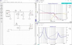
The XO was done on XSim with help from some experts on a Facebook group I belong to - not perfectly smooth and I will be working on that, but a decent starting point. I have no measuring mic etc. and that + software will be my next investment; though I have a room EQ engine on my A/V receiver, I suspect I can do better.

Ultimately I want to go full active XOs with DSP, but for now passive is what I will be working with.

I welcome any/all comments/input/recommendations.

Thank you for taking the time to read.

Attachments

  • AM1.jpg
    AM1.jpg
    123.8 KB · Views: 295
  • AM2.jpg
    AM2.jpg
    111 KB · Views: 297
  • AM XO.JPG
    AM XO.JPG
    236.4 KB · Views: 294

Maplin derivative 75WRMS lateral mosfet amp.

FS: Maplin derivative 75WRMS lateral mosfet amp.

New build Maplin 75WRMS lateral mosfet power amp.
Uses Exicon laterals which cost me £20 for the pair.
Choice of TO3 or cheaper TO247 output transistors.
Requires power supply and heat sink.
Asking £29.99 plus p+p
p+p is £4.20 to UK and £12.99 to Europe and £18 to rest of world.
Nice detailed sound.
I took Maplin (Hitachi) circuit and added extra decoupling on front end. Added DC offset adjust.
Uses modern easy to find components.
zzz.jpg

  • Poll Poll
ULTIMATE OPAMP SHOOTOUT... Where you get to decide.

Which opamp do you prefer the sonics of ?

  • Apple

    Votes: 2 5.0%
  • Banana

    Votes: 7 17.5%
  • Damson

    Votes: 1 2.5%
  • Kiwi

    Votes: 1 2.5%
  • Orange

    Votes: 6 15.0%
  • Peach

    Votes: 6 15.0%
  • Pear

    Votes: 3 7.5%
  • Pomegranate

    Votes: 11 27.5%
  • Raison

    Votes: 2 5.0%
  • Satsuma

    Votes: 1 2.5%

Polls. There is a poll attached to this thread where you can vote for the best sounding opamp.
There is also an additional poll CLICK HERE where you can vote for the worst sounding opamp.

Edit There is an additional new "quick fun test" at post #88 CLICK HERE

From the industry standard 741 to todays dedicated high performance opamps that are firmly aimed at the very top end of the audio market these common devices generate huge interest and polarise opinions. How far have we really come though in the last 40 odd years ? I thought it would be a really fun thread to take some common devices and put them to the test... or rather, for all you out there to put them to the test by actually listening. Could you identify a 741 compared to say an LM4562, or a TL072 versus an NE5532. Well now is your chance to find out 😀

OK, so this is what I have in mind and of course I'm constrained by working with what I have available which is just a Dell and Acer laptop and Audacity. The source is a Marantz Pearl Lite SACD playing a test file I have prepared, the file consisting of four short music snippets. These are loaded onto a USB drive and plugged into the Marantz USB port. The basic opamp circuit consisting of two opamps per channel is shown here. It is a simple attenuate/amplify/attenuate/amplify scheme where the signal is brought back to approximately where it started amplitude wise. Its a tougher test than it looks though. Have you noticed the output loading on each opamp. 680 ohms plus driving the feedback networks.


(Note, R9 and R10 are 680 ohm and not 620 ohm


So here is how the test works. We take the analogue output signal from the Marantz and pass it through each opamp test circuit, digitising the final opamp output using Audacity. From this a 320kbs MP3 and WAV file is generated. Its up to you which you use (the MP3 files are around 7.5mb and the WAV just over 30mb). We do that for each of the opamps under test. And all you have to do is listen and try and decide what is what. It would be great to hear any comments on how you feel each snippet sounds too. All you will have to work on for identification are the file names all of which are named after fruit. So if you think "Damson" is the best then mark it as 1st place and so on.


The opamps I had available are 741, 4558, 4560, 5532, LM4562, OPA134, TL072, TLE2072 and a "wild card" that if all goes to plan would only be revealed at the end of the test. Oh, and the original file of course played direct.


So what do you all think 😀 Interested ?
(I can use dropbox to post the files 🙂)

Here are the files,

Apple MP3 https://www.dropbox.com/s/4pxj0gkqqhbha96/Apple MP3.mp3
Banana MP3 https://www.dropbox.com/s/sqqawagzxowro5o/Banana MP3.mp3
Damson MP3 https://www.dropbox.com/s/1xcjrz2ec4xs16s/Damson MP3.mp3
Kiwi MP3 https://www.dropbox.com/s/g5nu8s2omr42nur/Kiwi MP3.mp3
Orange MP3 https://www.dropbox.com/s/7tsula4xkkub288/Orange MP3.mp3
Peach MP3 https://www.dropbox.com/s/y0cqmn0a97qma4k/Peach MP3.mp3
Pear MP3 https://www.dropbox.com/s/v7hvtvravthp17p/Pear MP3.mp3
Pomegranite MP3 https://www.dropbox.com/s/09geygvwi6xb9h2/Pomegranite MP3.mp3
Raison MP3 https://www.dropbox.com/s/4pi10guur2p7ebp/Raison MP3.mp3
Satsuma MP3 https://www.dropbox.com/s/87mmvuza6qhzzzy/Satsuma MP3.mp3

Apple WAV https://www.dropbox.com/s/dfk0id2s7ffxnws/Apple WAV.wav
Banana WAV https://www.dropbox.com/s/uxiftiqoh3dyxi7/Banana WAV.wav
Damson WAV https://www.dropbox.com/s/19w57e4cyvpxwfs/Damson WAV.wav
Kiwi WAV https://www.dropbox.com/s/xyfrfn5duau19g5/Kiwi WAV.wav
Orange WAV https://www.dropbox.com/s/6tzpw9bere56fvn/Orange WAV.wav
Peach WAV https://www.dropbox.com/s/m5h3ygpxx9yniy6/Peach WAV.wav
Pear WAV https://www.dropbox.com/s/9idk24bb1kusysi/Pear WAV.wav
Pomegranite WAV https://www.dropbox.com/s/v5774o1digxe5ku/Pomegranite WAV.wav
Raison WAV https://www.dropbox.com/s/nvpayrm6l4929zc/Raison WAV.wav
Satsuma WAV https://www.dropbox.com/s/f1vavw94v9qqang/Satsuma WAV.wav

Arylic Up2Stream Pro V3 cannot connect to DAC

Hi Guys

I get a bit scared asking questions here because you all have far more knowledge than I…. but I will try.

Also, I have no idea which Forum this would fit into.

I bought an Arylic Up2Stream Pro V3 early-mid 2020 and I have trouble with it…

I also bought the SPDIF output board.

I would like to play music using the Wi-Fi (well anyway) and stream/connect (not sure the correct term) to my DAC using Media Monkey 4 software.

Arylic support are not helping/responding and Media Monkey leave me messages that I do not understand.

Can anyone help an idiot??

Hello from the UK

Hi all, I'm Chris and I'm from Ascot in the UK, about an hour outside of London. I've joined here recently because I've started getting into DIY audio, but so far have only done a few kits. My main setup is a Rega Planar 3 (w/ mods) with an AT-VM95ML cart going into a Trichord Dino MKII with Dino+ power supply. That goes into a NAD C316BEE integrated amp. The speakers are KEF Q55s. All of this was bought at pretty good second-hand prices. I have a Naim NAC 112 preamp, that I cannot use with anything because I don't have a power amp that can power it, or an external power supply, so I will probably be asking for some advice about that in due course!


I have a few headphone amps as well that I use with my Sennheiser HDXXs, a Drop THX aaa One, a Schiit Vali 2 and a Bottlehead Crack with the speedball upgrade. I thoroughly enjoyed the Bottlehead kit, and I would love to do some more. I recently acquired a Quad 306 power amp with some issues that I would like to fix, so I will be making a post regarding that later today.

Thank you for having me here!

How Best to Add Tubes to a Buffered Volume Control?

I've been impressed after living many months with a Tortuga Light Dependant Resistor volume control. SQ went up again when I tweaked a Yaqin CD3 (6SN7) tube buffer to add to it. Even though for some reason the Yaqin sounds better placed upstream from the Tortuga.

This leaves the 20k impedance Tortuga VC playing into the 20k input impedance of my power amp. Thinking my system would benefit from an output buffer to help with dynamics/punch, I have a solid state buffer kit (also from Tortuga) on the way. BUT I would like to keep the tube magic (or distortion--call it what you will) I now enjoy. But I would like to do this in the best way possible i.e. retaining the tube magic while minimizing noise and impacts on clarity and immediacy.

My first thought was to find a minimal-circuitry tube buffer that can use 6sn7s. I was perusing the Glassware site and the 12VAC tube buffer caught my attention. Maybe because the Tortuga stuff runs on 12V or maybe because I had just been reading about people's success running 6SN7s at low voltages, attaining lower noise figures as a result. Then luckily, I realized I don't really have enough info to know what direction to take.

So my questions are:
1) Can I get a meaningful increase in SQ by replacing the Yaqin upstream of the VC with another type of tube buffer-- OR -- some other approach to injecting a bit of "tubeyness"? (See as only one example John Broskie's balancer and unbalancer boards.)
2) If yes, what specifically would you suggest? If it's available in the EU that would be a plus.

Thank you in advance -- Rob

Few questions about constructing my first amp.

The amp is for 10inch reference sub. I have a active monitors and would like to filter some of the lower frequency that they receive and control the frequency of the sub independently.

1. Can I use a duel channel amp on a sub, can I just bridge the output? I was thinking about getting the shui yuan Audio TPA3255 2.0 Digital Amplifier board.

2. How do go about filtering the frequencies to all 3 speakers. Should I get some sort of DSP, or is there a good analog way of doing this on the cheap. Can dsp's even control 2 different sets of frequencies. What can you recommend?

3. Maybe there is some preamp I use for part of filtering, if not how does one control the volume on these boards? Do you control it changing the voltage?

4. Failing to find that much documentation on getting started. If you could point me some diagrams or learning resources that would be nice. Need some guidance to help me on my search, hope you can find some time to point me in the right direction.

Thanks

Plinths from eBay

I was wondering if any has ever used one of the plinths for I guess most table that can be purchased off the bay.

I had been looking for an older Rega Planar 3 and happen to run across. Now I understand most manufacturers have their own way of making the plinths so I am wondering what sonic input these type may or may not have.

If anyone has used one and wants to say how they worked that would be nice.

Here is a linking showing some that came back when I searched for “Rega”

https://www.ebay.com/sch/i.html?_nkw=rega+plinth&_trksid=p2380057.m4084.l1313

Budget 300b tubes recommendations

Hi,

I'm building PSE 300b monoblocks and I'd like your opinions on 'budget' 300b tubes. As I need 4 of them, I'm searching in the range of max 400 euro/dollar for 4 tubes (with shipping and import taxes, euro and dollar is about the same for me)

On my shortlist:

Psvane Hi-Fi series at $300
EH 300b at €270
EH 300b Gold at €310
Shuguang 300b at $320
JJ 300b at €400

Any comments on the relatively new Psvane Hi-fi series? Everybody seem to like the more expensive psvane tubes but I can't find anything on the budget series?
In old threads I read the Chinese can sound good but often have quality issues, but also that they are getting alot better in the the last few years.

The Electro Harmonix tubes seem to get good reviews. Is the gold series worth the extra cash?

I tend to like the 'warmer' sounding tubes.

Thanks in advance

Custom build for Mcintosh MC30, C8 and C8S

Hi everybody,

I’ve had a pair of McIntosh MC30 amps and a set of C8 and C8S preamps in boxes for about ten years and lost track of them until recently when I took them out of storage and brought them to a specialist for a makeover. That part was easy.

I always had doubts regarding speakers, as there are a lot of recommendations out there and the lesson I’ve learnt is that choice of speakers usually comes down to personal preference. The ones I have available are a pair of Bang and Olufsen Beovox 5000 mk2, but I’ve never heard them play, and they’re such a specific brand that either no one talks about them, or aficionados have nothing to compare them with.

When it comes to pairing MC30s with speakers, the usual suspects are Klipsch, Tannoy, JBL and Altec, and everyone has a specific model they swear by which is great, but ultimately unhelpful when it comes to making a choice because it all depends on what you listen to and where it is you intend on listening to it.

So I’ve been thinking of building custom speakers, tailored to the set up and the intended use.
Let’s talk about that : I mostly listen to 60’s 70’s classic rock, a fair amount of blues, and I do enjoy some 80’s and 90’s pop but not everyday. I’ll be using these amps 90% of the time with vinyl (front end is a Garrard 401 with and SME 3012 tonearm), though it’d be nice to clip in an Iphone during dinner parties because in those moments it’s just easier to stream a playlist.
The biggest issue I face is my apartment : I live in a 48 m2 converted store front, which means two of my four walls are glass, and the remaining two are occupied with bookcases and a kitchen. It’s got a big ceiling height, but very little space against walls. At this point a lot of people might think there’s no point in trying to set up a decent listening space in these conditions, but I love my apartment And I don’t intend to move just yet, so the point is to make the best of it. The ideal solution would be rather compact free standing units. I don’t need too much bass, as I don’t usually listen to electro etc and in any case my amp/preamp set up isn’t suited for that.

I’ve done reasearch on “period correct” speakers and the ones that I like best for my brief are on paper Altec 14s. From what I read, the mid range is superb and horns really come into life with the MC30s. They’re not extravagant in size (I don’t live in a warehouse and I’ve got neighbors to consider) but they are hardly available, especially where I live (Paris, France).

Technology has evolved since the 50’s-80’s and I’m sure I can build some honorable custom units, but I need advice if I’m to go down the DIY route. I’m handy with tools and have 3D software and a workshop I use everyday, but my knowledge in available equipment and acoustics is limited to say the least (I’ve only just started using WinIsd), which is where the community comes in.

What would your dream speaker for this set of parameters be?

Many thanks for your imput,

Max

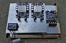
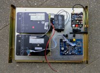
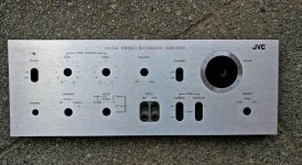
Integrated 4 channel class D-amp in JVC vintage housing - some questions

Integrated 4 channel class D-amp in JVC vintage housing

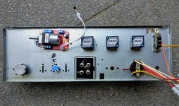
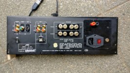
Hi together. I am planning to build a "new" integrated amp into an old nice vintage housing and have some questions to the experts.

As you can see on the pictures, i want to create a four channel "main" amp, made of two Wondom Modules. In addition, I want to use a small one-channel Kemo Amp for some quick speaker measurements (there's a nice line-in on the front i want to use for my soundcard).

A miniDSP 2x4 HD will drive the two Wondom Modules, a motor-driven Alps-Potentiometer reduces the incoming signals of a DAC-Board, a Bluetooth-HD-Board and a Creek phonoamp. I don't want to use Dirac or the digital imputs of the miniDSP 2x4 HD.

In addition, the Alps motorpotentiometer drives an unfiltered pre-out on the back.

As power-supplies, two 150 watts linear power supplies (Ebay ;-)) are going to supply 24 Volts DC to the amp modules, as well as the phonostage, which needs 24 Volts too.

For the rest (DAC, DSP, Bluetooth and potentiometer) I need 12 Volts DC. A Kemo step-down converter is going to do this job.

As you can see, I want to put a lot of stuff into the old housing. Therefore, i asking myself, which is the best way to avoide noise and hum.

For now, i want to use a single ground point for the power supply and the amp modules and try to decouple the inputs from the housing ground (i will need other cinch sockets, the gold ones on the picture are too big and touch the steel back).

Is this a proper way to avoid hum and noise? This the main point i am worrying about.

Is it a better way to put the whole power supply for the 12 Volt into a separate housing?

Or do you see mistakes I'm not aware of yet because of limited experiences?

Advice welcome.

Regards Ludger

Attachments

  • Module und DSP k.jpg
    Module und DSP k.jpg
    607.7 KB · Views: 245
  • Netzteil und Co. k.jpg
    Netzteil und Co. k.jpg
    613.5 KB · Views: 251
  • Front k.jpg
    Front k.jpg
    439.8 KB · Views: 235
  • Front hinten k.jpg
    Front hinten k.jpg
    475.1 KB · Views: 225
  • Heckansicht k.jpg
    Heckansicht k.jpg
    475.9 KB · Views: 222

Voice coil centering technics during refoam

Anyone a speaker refoam/rebuild expert? I am curious about voice coil centering technique's during the refoam process?

I recently had my dynaudio woofers refoamed and I spent a great deal of time searching the web for experts. with a conventional woofer, most shops cut the dust cap off and place shims around the voice coil to align it while gluing the foam in place. With Dynaudio woofers you can't do that as the cone/cap is all one piece. one shop told my they just cut the dome out and glue in a felt cap! ugh!

So after much searching It was suggested to me that a certain company had a proprietary method of "electrically" centering the voice coil. this interested me. But by the time i got around to being able to ship the woofers, the shop no longer wanted to do Dynaudio woofers! I ended up using a local shop and well...they work, and i guess that's what counts but i wasn't exactly impressed with there work.

After more web searching and watching many youtube videos on refoaming, it seems that this "proprietary" electrically centering process is probably nothing more than applying a low frequency signal to the woofer while manually manipulating the woofer foam into place so the voice coil doesn't rub. not exactly rocket science. but not exactly perfect either.

SO, I am curious if anyone knows of any special techniques new or old that this company that shall remain nameless, might have been using??

I'm curious how Dynaudio actually does it?? I would love to see how that's done!

Zc

Did they just stuff the 6F6 guts in a 6K6 with a new heater and cathode?

I was looking up the 6F6 as I have two old radio chassis, one missing the field coil speaker (darn) and someone was felling a bunch of 6F6's. They look to be the same other than the heater draw and the 375V pentode and 350V triode specs on the 6F6.


http://www.r-type.org/pdfs/6k6gt.pdf
https://frank.pocnet.net/sheets/127/6/6K6GT.pdf


https://frank.pocnet.net/sheets/127/4/42.pdf

Altec Lansing FX6021

Hi everyone. My first post here.

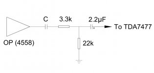
I was given a set of Altec Lansing FX6021. It's quite old but sounds not bad. I took the mainboard out from the sub to see if it's worth for mod. It uses a TDA7295 to drive sub and 2 TDA7477 for satellite speakers.

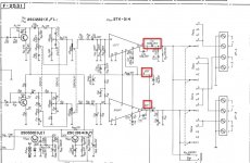
One tiny SMD cap caught my attention (See "C" in the attached). This tiny cap is no more than 100pF, I guess, but it connects 4558 to TDA7477. What's its function? Why it doesn't filter out lows & mids?

Attachments

  • FX6021.jpg
    FX6021.jpg
    31.7 KB · Views: 226

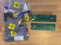
Pass AB-100 PCB/Part kit

Hi,

I decided to build another AB Amp and will offer the PCB‘s (layout by Prasi, 2oz Cu…) and many of the needed parts.
I payed around 96€ for the parts and 16€ for the PCB‘s that is also the price for this offer (plus shipping).
Shipping is from Germany.

Daniel

Attachments

  • 3F65DB2A-4B50-486B-8D68-7188870E83C6.jpeg
    3F65DB2A-4B50-486B-8D68-7188870E83C6.jpeg
    114.8 KB · Views: 642
  • 887FCD8A-6BE2-4797-8645-EECFAF250375.jpeg
    887FCD8A-6BE2-4797-8645-EECFAF250375.jpeg
    130.9 KB · Views: 632

build small simple cheap full range speakers for my 2.1 system...

first time project, I want to expand my knowledge of carpentry , electronics and DIY in general.

SIMPLY PUT

I want to make a pair of VERY simple TINY speakers for my desk, I have a little 2.1 amp and a subwoofer below. I want it to be dirt-cheap so I wanna build with reclaimed wood, upcycling as there is so much waste wood in the streets around in London where I live.

Going for cheapness and simplicity I would like to opt for two single driver speakers and closed back. At that size I think that is about right.

Ideally they would be about 20-30watts each...

So two little cubes basically!

I have no idea where to start and I didnt want to trawl through tonnes of hard core technical stuff, I am not good with maths and stuff.. Just wanna keep it simple and practical.

I know that I need to choose some drivers then work out the dimensions of the speaker based on those..

So there is a formula I need for this right?

And maybe I wont need a cross over if its just a single full range driver in each of the speakers?

Thanks!!!

Current Dumping, Class A Performance With No Idle Current

I came across this blog. Current dumping for dummies? – CONNERLABS

The most well-known implementation of "Current Dumping" is Quad 405.

The "Current Dumping" topology claims to eliminate the crossover distortion with no idle current at output stage. Is that true? or just a marketing things?

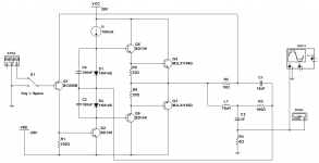
Here is my little experiment.
sch.PNG

sim.PNG

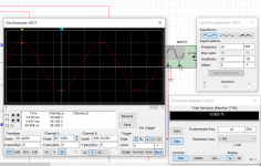
It holds its claim pretty well. 0.002% THD@10KHz under +-20Vp-p.
The number is even better than an average Class B amp.😱

Hybrid Circlotron - DC offset, what have you used?

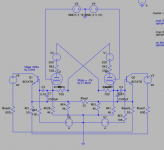
So my OTL HPA project backend has moved to a class A circlotron. Actually two - one for tube and one for a pair of helper BJTs. The design is based on using the tube output rather than tube input into the base of the SS output stage. The idea seems to work, at least on paper/LTSpice. It also seems to scale between 32ohm to 600ohm however I still need more experimentation. However before that - I need to tackle the DC offset.

Screenshot 2021-09-11 at 09.44.51.png
(ignore the spurious labelling of resistors)

Broskie has used a pair of cross linked LPF from in the input to the opposite phase to balance DC but I'm interested in alternatives and if the added complication of say active opamp makes a difference.

I suspect I'll need to use two - one for tube DC offset and one for SS offset with the risk of oscillations.

An Aleph 2 for $27K in ebay

So, someone has posted a pair of Aleph 2 on Ebay... I guess it "pains" him to even sell them because his must be special.

$27K.

Pass Aleph 2.0 pair of Monoblock stereo amplifiers | eBay

Now, I've been wanting a pair of such amps for years. They tend to go around 3500 to 4K... and I got quoted about 1200 ( shipping is $$$) from the factory to recap them.

I gave the guy an offer which is fair... specially as he really doesn't say what shape they are and has not even bothered to post pictures.

Surely, I hope not to hurt his ego... if he moves on my offer, fantastic.

And as my wife said: "Honey those are pretty ugly amps"... to which I replied: "Well, that's why the Maggies are such wide speakers, we can hide the amps right behind them:... ;-)

Low DCR Chokes: Will it improve transients/dynamics?

In talking with a friend, he suggests using low DCR chokes for the powers supply, on the order of < 10 ohms per choke.

I am currently using 10H/225mA/51 ohm chokes. In your experience, will changing chokes to a 5 ohm DCR result in better transients and dynamics compared to the 51 ohm chokes? I would use the same brand/specs, Monolith Magnetics but just lower the DCR to 5 ohms. I am trying to get a bit more snap / liveliness to the sound.

Thoughts?

Attachments

  • C3g-45B v13 7.28.21.png
    C3g-45B v13 7.28.21.png
    77.8 KB · Views: 1,019

Sonic Quality of L-pad attenuator for tweeter

I just want to conform from other members here that does Lpad attenuator affect sonic quality of tweeter. I tried a tweeter with 6db Lpad attenuator another without attenuator. but reduced the same db at amplifier to match the output at tweeters. what I felt was the tweeter without Lpad, Sound better crisp and clearer, and sound more natural.
Just want to know from you all here is , what difference I heard, makes sense or just my illusion. Also is some body can explain how series resister in attenuator makes the difference. resister in series of any driver affects the damping of driver. so how this affects tweeter?

Regds

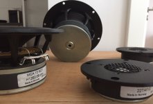
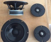
FS: pairs of SEAS MCA15RCY and 22TAF/G drivers

FS: pairs of SEAS MCA15RCY and 22TAF/G drivers -SOLD-

selling pairs of SEAS drivers in good condition, only used for a short period of time in a non smoking area
2 pcs SEAS Prestige MCA15RCY - H1262-08 5.5" Coated Paper Midrange
2 pcs SEAS Prestige 22TAF/G - H1283 7/8'' Aluminum Dome Tweeter -SOLD

asking for half of the current price: 130 Euros plus shipping -now 80 Euros for the MCAs -reserved for Jim

all sold -thanks a lot!

Attachments

  • Seas2.JPG
    Seas2.JPG
    542.1 KB · Views: 319
  • Seas1.JPG
    Seas1.JPG
    707.2 KB · Views: 320

Valve rectification question

Gents,

I am trying to understand more about my 211 amp, and it has two 5u4GB rectifiers, and on the main transformer only 0 450v apparently no centre tap. ......I think...

Could it be a voltage doubler circuit maybe?

Is there a good way to see how the circuit works without a strip down, as a lot is out of sight.

Can I learn anything by taking some measurements from the 5u4 valve base etc.

211 is at ~1000v, so yeah I know it's dangerous poking around!

Just trying to learn things, no real reason other than initially trying to understand if my driver valves are diode or valve rectified.

Thanks,

Refreshing of Audiolab Pre-Amp

Apologies for the long winded post and I hope I posted this in the right section of the forum.
So this Audiolab 8000C has been my pre-amp for what must be +10 years now and is paired with a 8000P power amp, the latter being in mint condition and rather well looked after.
The pre on the other hand I got totally screwed when buying it, other than the age the thing was caked in heavy cigarette smoke and whilst it doesn't smell any more on the outside, the inside still smells and is coated in a thick layer of tar.
At that point I pretty much gave up and just ended up using it as is for god knows how long.

It's always had some issues i.e. scratchy pots with poor channel matching, faulty relay, susceptible to mains pops and a scratchy eq on/off button.

Now instead of buying something else and selling this (it's pretty worthless in it's current state no?) I thought it would be nice to get it back up to spec as it's not a bad pre but just needs some TLC.

Plan of action so far is as follows;

Replace all Electrolytic capacitors > Ordered ELNA Silmic II's and Nichicon LKG for the PSU mainly cos the solder tabs just make it easier and they're easily available at Mouser.

Replace Volume and Balance pots > Still Need to source

Replace Relay > Still Need To Source

Now I am not an expert and would love peoples suggestions/input on here, am I missing something etc.
The pre-amp obviously gets hot, those transistors with the heatsinks are very close to the caps etc.
Is it worth while replacing some of the polyester and polystyrene capacitors in the future too?

I am having difficulty sourcing suitable pots (Noble dual log 30k) and if anything will use a 50k pot albeit I still have difficulty sourcing something of that particular size and that is of quality.
Almost thought of using a ALPS RK-27 and just using jumper wires instead of mounting it to the PCB although size is probs an issue.

Switches.. One day haha One thing at a time at the moment.

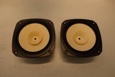
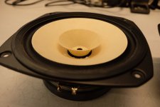
FS : Fostex FE206En full range (pair)

Hi,

I'm selling a pair of Fostex FE206En in mint condition, approx. 50h of moderate use.
Shipping to Europe only.

Price 135€ for the pair.
Shipping is about 16€ to most European countries.

Attachments

  • 2021_0904_05240700.jpg
    2021_0904_05240700.jpg
    653.5 KB · Views: 231
  • 2021_0904_05242000.jpg
    2021_0904_05242000.jpg
    632.9 KB · Views: 222
  • 2021_0904_05243000.jpg
    2021_0904_05243000.jpg
    669.6 KB · Views: 217
  • 2021_0904_05243400.jpg
    2021_0904_05243400.jpg
    601.3 KB · Views: 211

Pre outs on Rotel to sub & full through Speakers???

Hi
Please correct me if I'm wrong but its my understanding I can connect my powered subwoofer to the pre out (not sub out) connection provided on the rear of a Rotel rx950ax receiver I'm looking at?

My question is, as it will be sending full range audio to my subwoofer amp through its pre out will the Rotel still then be able to play full range audio to my stereo speakers connected to it while at the same time sending full range to the subs through its pre out?
Regards
Tim

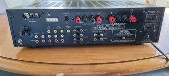
Rotel rx950ax rear pre outs
ad_1631145203708.jpg

T2500-1bdcp rockford help.

Hey guys I have a rockford t2500-1bdcp on the bench. The unit would power up then directly into protect. It had some blown output fets. I replaced the out put fets and the amplifier will turn on and play however it is drawing about 9 amps of current at 14.2 volts and one of the voltage regulators lm337t is getting hot and heating up the top left of the heat sync. Is this normal? I have not hooked it up to high current yet so I don't know how the amp acts under a load.

On The Back Burner 7 Watt 6EA7 PP Amp

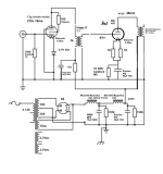
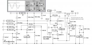
This is a minor project I hope to nail before Spring 2021. The beginnings can be traced to the 6SN7 Push Pull Flea Amplifier Project by Lingwendil.
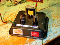
I got into the thread around Post #250, Fall of 2018. I was concerned that the proposed OPT would not properly load the PP 6SN7. Along the way I built a test chassis on a Betty Crocker cake tin, so I called it the Betty Crocker Special. The octal base pin out of the 6SN7 is the same as the 6BX7 & 6BL7. Tried those too.
Audio power is limited by the plate dissipation of the various tubes. I found in Class A & properly loaded OPT 3 watts could be got from a 6BX7 or 6BL7. The 6SN7 was good for about a watt at clipping. A friend donated a 5998 much higher powered twin triode for the tests. The 5998 managed 10 watts before clipping.
That group of twin triodes dissipate all the waste heat in one bulb. With a pair of 6EA7/6EM7s the waste heat can be shared by two bulbs. Simulations shew the possibility of a very compact, all triode amp capable of seven watts audio. With some wiring changes it would be possible to try that on the Betty Crocker amp chassis.
All externally powered by my home grown regulated PS. And I'll never build another amp, experimental or otherwise on a Betty Crocker tin. Not very convenient at all for making test measurements or circuit mods.

Attachments

  • 6EM7 Triode Amp 6EM7 Driver Common Bias D2.JPG
    6EM7 Triode Amp 6EM7 Driver Common Bias D2.JPG
    94.4 KB · Views: 604
  • 6SN7 Amp Betty Crocker Special.jpg
    6SN7 Amp Betty Crocker Special.jpg
    589.9 KB · Views: 631

Pure Player

Hello,

My belief is that most audio player software for Windows sound quite bad and this fact made me develop my own music player. It's free and you may download it from http://pure.truefreehost.com/pureplayer.zip (copy the url to your browser). Very simple, possibly full of bugs (early alpha version), but i believe it worths an audition... 🙂

Installation instructions:

.NET 4 framework required (for the GUI, the core is written in pure fast C)

Unzip pureplayer folder to c or any path without spaces.
Copy PurePlay Shortcut to Desktop and doubleclick it.
Press the "Readme" button 🙂

Looking forward for your reviews...

japanese speaker plans

I found a web site by a guy in japan with dozens of rear loaded and loudspeaker plans. They werent very large, maybe the biggest was 24"-30". It was a personal site. Computer crashed and lost the book mark. I dont know how I found it, but ive been searching and searching and nothing. Sorry dont have any other hints on whats on it. But the plan were pretty detailed. If anyone knows of the site or something similar can you please help me. Thank you.

Can I use a simple zener circuit to step down voltage for a turntable motor?

I have been given a broken JAM turntable which has a USB/digital output. The main board is basically kaputt but the motor, speed selector switch circuit and transformer/power-in circuit seem to be working ok so I want to convert it to just a simple analogue-only record player.

The motor is a 9V/12V pretty much like this one...New 13s/lot DC9~12V MOTOR with all switchs and wires 33 1/3, 45, 78RPM / turntable gramophone Plattenspieler|switch shell|motor figuremotor sliders - AliExpress
but the transformer and power board (bridge rectifier and filter cap) puts out 20VDC (previously it supplied the main board which then fed the motor with the required voltage (12VDC).

So basically I was thinking I could use a 12V zener diode to regulate the voltage to 12V to then supply the motor. Would a circuit like this work (call it 'circuit A')...?

https://www.electronics-tutorials.ws/diode/diode_7.html
(first pic on this page)


I was thinking if I get a 5w 12V zener then it would have a max current of around 410mA so the series resistor would have to be around 20ohms if Vin is 20V. Can it be that simple or am I missing something?

Another circuit I was looking at (call it 'circuit B')) was this one ... 12 Volt Regulated power supply circuit using zener diode ... which specifies motors in the description. I'd have to change some of the values here as this is 15V to 12V. Also I don't know what the transistor is for in this one...?

Any thoughts gratefully received...

Tom.

Ceramic phono carts. Are they so bad?

This summer there came to me the hare-brained idea of testing how good ceramic phono carts are - or are not. I know they are a relic of bygone days, but almost all the old consoles and record players I've restored used ceramic cartriges.

Ceramic carts are high output and need little to no EQ if the proper preamp is used. I have a nice new Sonotone (AKA Garrard) cart and a good old EV from my Clairtone. How well can they perform? I mounted the Sonotone on my AT tonearm with a new headshell and gave it a spin. The ceramic cart and headshell are so light that they float where the AT95E has 2.5g of tracking force. A dime on the headshell and a little balance adjustment got me to the 4.25g needed for the Sonotone.

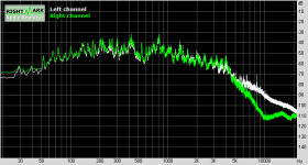
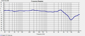
It pugs right into my USB sound card and at 0.48V output, as more than enough level. It does suffer HF roll off, even tho the instrument input of the soundcard is supposed to me 1 Meg ohm. Below you will see two graphs, the shaggy one from RightMark shows the FR from a song on an old mono LP. White is the AT cart with RIAA, green is the ceramic straight in. The smoothed graph used the AT cart as reference and the plot is the FR of ceramic.

A more suitable preamp is the next step. That should fix the HF roll-off. Why all the bother? Because it's too damn hot to go out and work in the garage. This can be done in comfort. 😉

Attachments

  • MM vs CC music FR.png
    MM vs CC music FR.png
    13.9 KB · Views: 326
  • MM vs CC.png
    MM vs CC.png
    18.9 KB · Views: 315

Markaudio Studio Main Monitor build

Posting this in the Fullrange section instead of the Multi Way as this is mainly about Markaudio Drivers, hope thats ok.

Some while ago i build a 2-Way System using Markaudio Chr-120 and Chr-70 in an oversized sealed box (q around 0.4), first order crossover @470hz to compensate for baffle step response. Worked like a charm, i absolutely love the sound of these Speakers and also noticed that theyre actually better for mixing work than my and most other studio monitors I worked with and listened to, much more detailed, consistent soundfield and insane transient response.

To the point, this made me decide to build the main Monitors in my Studio myself, using Markaudio. Knowing from lurking and reading this forum some of you got extensive experience with these drivers, maybe you can help me with some questions still in my head.

1. Im planning on upgrading from the CHR to the MAOP drivers, so MAOP 11 + MAOP 7 - If I like the CHR sound is this a good idea? the consensus seemed to be the alpair are similar to the CHR in terms of overall character but just plain "upgrade".

2. The CHR-120 extends pretty low in a sealed box, MAOP 11 doesnt quite get there. For full range reproduction the Plan would be to go 3-way and add a bass driver for everything below the MAOP 11. Just feels kind of wrong to me in some ways, as i kind of dont want to **** up the minimal crossover design with an additional capacitor for the MAOP 11. Any of you had any experience with WAF designs, specifially the low pass filter for the sub?

Thanks!

FS: Klaudio KD-CLN-LP200 (Pump not working)

Removed: Klaudio KD-CLN-LP200 (Pump not working)

For sale is my non-functional Klaudio KD-CLN-LP200. The ultrasonic transducers were replaced by Klaudio in 2018 (can provide the service history). The drying cycle still works. However, the fill pump makes unhappy noises and causes the cleaning cycle not to engage. Physically, the unit is in immaculate condition with one exception - I'm missing a couple of the very small black screws that hold the rear body panel in place (but I'm sure if you know what to order, this is a $2.00 cosmetic fix). I have the original box and materials. Pictures (and video w/ audio) available upon request.

$500 + $100 for shipping within the continental US.

** Updated - Listing removed as unit has been returned to Klaudio for repair and updating. Unit may be relisted at a future date. **

Glassware ACF-2 cathode follower octal vs 9-pin questions

Hi all. I recently made a thread (albeit in the wrong section) asking for advice about what kind of line stage to build to go with my setup. Link here: Reccommendations for a preamp build based on my gain and impedance needssetups

The conclusion, with a lot of help from rongon, is that I need a near unity gain line stage, to go with my Quad 306 amp and Trichord Dino phono stage.

I am pretty set on getting one of the Glassware cathode follower kits, in particular the ACF-2. However, I am not sure whether to get the 9-pin or octal version. I have tried to find out the differences between them, but I am struggling to make sense of it. I have read a lot of conflicting opinions on the differences, from views such as that octal tubes offer more gain or octal tubes can offer a 'fuller' sound, but also views in the complete opposite of this.

I was more set on getting the 9-pin version, I think, but now that is out of stock. The octal version is still in stock, so I would like to get some opinion on what might suit me best if possible.

I have tried to contact John from Glassware with a few questions, but unfortunately, he has not got back to me. I have read elsewhere that his email inbox gets filled with spam so sometimes messages can be missed.

So, in short, I guess what I'm asking is what are the differences between these two kits?

Thanks in advance for any help!

Bias Marantz PM80 MkII

Hi,
I should calibrate the idling current of a Marantz PM80 MKII.
From manual service in class A should be 180 mV after 30 minutes, unfortunately, however, by turning the trimmer to the maximum I get about 140 mV on the tester.
I have clearly disconnected the load of the speakers and placed the volume at minimum and the sliders in the center position.
Would anyone know how to solve this problem?

thank you very much

opinions on best player for.... Pi music player

Hello,

So the twist on this question is... what's the best music player solution for a Pi 1 Model B with a Hifiberry Digi that is so old that Hifiberry seems to have erased all mentions of its existence (and how-to's)... I originally started by looking at Pi MusicBox, but see on this forum that Moode, Volumio and Squeezebox(?) among others seem popular.

I'm thinking that I have to use an old version of one of these that still supports the Pi 1B and 26-pin Hifiberry dac...

Thanks,

clueless

Polyswitch fuse for speaker protection

Hi,
I want to protect the 1" HF horn ( 40W/8 Ohms ) of my bass guitar cabinet with a Polyswitch resettable fuse. If I have calculated well the result for my HF is 2.23A. Do I have to match this result with the trip current of the Polyswitch? The RXEF- 110 shows a 2.2A trip current : Digi-Key - RXEF110-ND (Manufacturer - RXEF110) .Is it the right one or do I have to choose another value ?: http://dkc3.digikey.com/PDF/US2010/P2107.pdf
Many thanks,
Pascalou

The new EWA M40 power amp.

1) The Design Concept.
A power amplifier design that is value for money and able to defeat the competition at four times its price.

To use if possible the SECA designs we have used in the past with more power output but less material waste in large heatsinks and huge energy demands.

The design was if possible to have a fast rise and fall time to cope with the demands of frequency to frequency phase changes.

It must also be able to go in standby mode if the users forget to switch OFF but be able to restart at the pre-set level on the input, in this design it is set to the equivalent of 1W into 8Ω.

It must have balance and un-balance inputs.

With the digital noise on the main power lines it must be able to ignore them.

It has to be over engineered in the safety area, such as the main power inputs.

The protection device to protect speakers must be fool proof.

The whole design must be based on K.I.S.S.

2) The Specifications.
Dual Mono Design one channel only shown, right or left.

Power output 8Ω @ 45W RMS , 4Ω @ 90W RMS, 150W peak into 2Ω
Maximum Peak Current 1mS 50Amps
Maximum Short Circuit for fuse to blow 6A RMS
Maximum Allowed Heatsink Temperature 40C
Input Sensitivity Un Balance 0.7V RMS into 22KΩ
Input Sensitivity Balance 1V RMS into 600Ω
Full Power Bandwidth 0.0dB flat 10Hz – 100KHz
Full Power Bandwidth -1dB flat 1Hz – 130KHz
Phase Angle change 100Hz – 20KHz less than 1Deg
Driver SECA stage A Class Power 1W
Output Device each channel six with very high speed and matched HFE drivers.
DC offset less than 1mV (typically 100µV)


3) The Block Diagram
The power inlet socket is a PCB mounted IEC with a built in fuse holder.
The Earth connection is to the chassis of the M40.
Live and Return are connected to a isolating power switch which in turn is connected to the mother board FR4 PCB.
Please note the slots in the PCB near and around the mains input live and return this is to provide extra safety precautions and to exceed the current regulations required for consumer products. Then we connect to yet a non serviceable fuse holder and fuse, this is help prevent customer tampering and increase the safety margin.

On the block diagram we show the POWER ON CIRCUIT this operates the start 16A relay with a Snubber Circuit around the relay contact to eliminate sparks and interference when operating. On Standby this circuit consumes less than 1W and in operation only 0.5W of the total power consumption. This block also has the two regulated power supplies for the RERERENCE VOLTS AND SENSE & TRIGGER CIRCUITS. These supply two ±V (V1+,V2+,OV1,OV2,REF V,V1-,V2-) and the 1.24V Reference voltages.
The TRIGGER POWER CONTROL section has two comparators which detect the input voltage on the power amp inputs and switch the POWER CIRCUIT on. The switch shown can be used to set the state the users needs, the QUICK ON SWITCH allows forced trigger to activate the power on timer of about 60 seconds this will turn off after this time if no signal is detected. The ON switch force the M40 to stay on in a continues state and the OFF switch keeps the amp deactivated and it will not trigger on.

The INRUSH LIMIT is to prevent the inrush current at peak mains from distressing the rectifiers and transformer. A note here all the main Bulk Capacitor are rated at a high ripple current, All other capacitors are designed to run in a temperature range of -40C to a max of 105C.
EMC & RFI FILTER’s 1&2 are rated at 4Amps each and are in common mode format.
The main power transformer is rated at 250VA with 8 output windings of 24VAC. These outputs winding are configured by the FULL BRIDGE RECTIFIERS to be out of phase, this allow the B/H curve to be used more efficiently when both channel need to draw a large current thus reducing saturation of the transformer.
The transformer is dipped and vacuum impregnated with a high temperature potting compound to reduce noise and provide more electrical insulation and thermal conduction.
Also wound with a µMetal magnetic shield and a Electrostatic shield to reduce the RFI and EMC emissions.
So the total noise RFI and EMC radiated and detected by the M40 is very low an increasing the quality of the music you hear without the garbage generated by our digital world.

4) The Amplifier modules.
The two amplifier modules are the same circuits to each other but careful layout of tracks help to balance their performance. These two PCB fit either side of the mother board on heatsinks.
The input has a DC blocking polycarbonate capacitor and a input impedance of 22KΩ, fitted with a small capacitor which roles the input frequency to -3dB at 14MHz, this may seem high but it allow us to have very fast rise a fall times on edges.
The next stage is a Long Tailed Pair which drive the PNP SECA drive stage controlled with a constant current, This stage is running about 1W, the DC offset is also controlled in the first stages reducing the DC to as low as 1mV (normally less)
This is simple KISS design but with very selective components, the driver and front end circuit are provided power from two (±) hum busting regulated power supplies located on the mother board. Each module has its own separate set of power supplies and there for is dual mono.
The next stages are complimentary drives, these high frequency device are normally used in radio circuit and have a high HFE for power devices, theses six transistors are forced to current share in the base drive and collector to emitter current, the HFE are match to within 1% of each set of six.
There is also another high frequency device mounted to the main heatsinks this in conjunction with a NTC monitor the inside chassis temperature and the heatsinks temperature and control the bias current in the six output power complementary power devices.
The six power devices are also HFE matched to within 1% of each set. The total IQ (quiescent current) is 1A running the power stages longer into Class A then into A/B.
Each device is rated at 150W PD and at a max current of 25A so we have plenty of head room.
There is no frequency compensation in the negative feedback circuit so very little phase change occurs.

On the mother board we have put timed independent speaker anti plop circuits this may cause one channel to turn on before the other, They are provide power by the main PSU after the fuses so if a fuse goes the speaker are never connected to the amp, keeping the safe.

The Balance circuit is done with a instrument amplifier circuit design to convert balance to no balance, This and the Balance input is controlled by a pair of signal relays operated by a toggle switch. Both can have connection at once from different sources and the selected by this switch.
The Balance inputs are set for the standard 600Ω but can be configured for any load up to 47KΩ on request.

Nearly all the components a precision surface mounted devices, resistor are low noise type and are normally under 10KΩ as this is the point noise rises dramatically in resistors.
All except a few power type are all 0.1% and the others are 1%.
The SMD power resistor are design in the rare case of a fault to desolder and drop off and not burn as we use low temperature Ag (silver) based solder. This also disconnects the faulty part of the amp from the rest of the amp.

So please enjoy you amplifier.

Kind regards and thanks.

Colin J. Wonfor

10/9/2021

Block diagram here, and yes you have to sign up but free
Oops, there was an error! | SECA
Problem with Adelphos woofer

Hi,

I finished the Jeff Bagby Adelphos kit, and it has boomy bass, in high
volume it's 'farting', here is a video:
Adelphos noise - YouTube

The cabinet is ported, I tried sealed but the bass sounds very elevated...more than the ported.
I 'upgraded' the crossover parts to Jantzen Alu Caps, Mills resistors and Jantzen Foil Inductors, all with same values.

The crossover is almost locked inside the cabinet, no easy access.

Any thoughts what went wrong and what can be done to fix it?

I tried to listen to other speakers in my room / electronics and no bass issues. Only with the Adelphos.

I tried the Adelphos with 2 different amps and got the same problem.


Thanks,

Itamar.

CD Player Schematics Help

Hi All,


I require some assistance clarifying a few things in the schematics for my Pioneer PD-91 CD Player. (I don't have years of experience with this, so please be nice 😀)

Here is a copy of the main section of the Schematics in PDF: View attachment Main Schematics.pdf


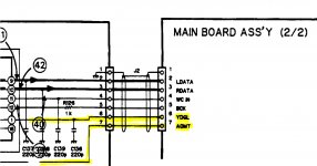
  1. Between the Digital Filter (YM3414) and the Serial-Parallel array, there appears to be 7 connections. I cannot identify 2 of these (labelled 'YDGL' and 'AOMT') - anyone know what they are?:

    Q1_Unknown Connections.jpg
  2. I cannot seem to locate the player's muting circuit. I think it is somewhere in this section of the schematics:

    View attachment Q2_Muting Circuit.pdf
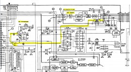
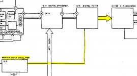
  3. It appears from this simple block diagram that the player's world clock is passed through the Digital Filter to the Serial-Parallel array. However, I have my doubts when looking closer at the Schematics. Could it be that the Serial-Parallel array has it's own standalone connection with the master clock?

    Q3_Master Clock Black Diagram.jpg

    Q3_Master Clock Schematics .jpg

    Hopefully you guys are able to help point me in the right direction!

    Thanks,

    Fish

Help Wanted w/ Playstation 1 mods/recap

Hello Everybody,

Is it okay to post a thread in Swap Meet when I'm looking for a tech? If so, I have purchased a Playstation 1 (1001 model) to use as my new CD player. If you're asking yourself "Do people still do that?" ... well ... I normally run several years behind when following trends. 🙂

I am going to do the teardown, cleanup, installation of a see through lid, and paint job. But my skills in working with circuit boards and a soldering gun are pretty rough. I am looking for somebody who has experience with modding a PS1. Rather than send the entire unit I could just send the power board for recapping (and re-resistoring if that can help the final sound). I can also send the board that has the analog output section for any upgrades, mods or recaps.

There used to be a dude on audio asylum and ebay who offered this service for $80, but he seems to be long gone. His name was Rich something. Anyways if anybody is interested in a quick little side job, please le me know.

Thank You

Remote mounting fets

I have an amp that has a heavy board (car audio class D) and between that and vibration it causes fet legs to break with a cascading effect. There is no way to better secure the board but is there a way to remote mount the fets to the sink using a copper braid between the PCB and the legs to isolate vibration/movement ? Has anyone done this and if so could you paste up some pics? I know thinks like this exist especially if you look at alternator/electrical motor brushes it is done this way. Only thing I need to make sure is if the braid can handle the current. I was looking at copper desoldering braid. Any and all input welcome... 😉

Arduino and MOSFET IRL540

Good day, all
I have the Arduino UNO and try to activate a valve, therefore I have the IRL540 MOSFET. On Gate we have the 0 or 5V signal from the arduino to switch (on/off), on drain we have 12V for the powersupply. But if we give the 5V on gate we only get 2,7V on the Source what is not enought to switch the valve.

Is there anyone have ideas o it? Thank you in advance!

Transistor and opamp noise floor measurement amp

Just a simple little test amp I'm currently boxing up to add to my "lab". Uses ultra-low voltage noise transistors in a differential stage. The intended use case is that the output goes to a sound card with differential microphone input, and spectra are recorded and plotted from this.

low_noise_diff_amp.png

The ZTX851's are 0.275nV/√Hz or so at 10mA, and a differential pair like this with 3.3 ohm emitter resistors gives about 0.5nV/√Hz floor for measurements. The supply is two 9V batteries, the 1.8V is actually a red LED as a voltage source.

I have a Scarlett Solo 3rd gen USB sound card which is 1.5nV/√Hz on the microphone input at max gain. This amp gains 9.5dB of extra noise sensitivity to this and retains the differential mode. Measured gain is about 35dB into the 3k input impedance of the Scarlett Solo.

In the circuit I've shown some ways to measure simple transistors and opamps for voltage noise (you can ignore V3 as it was solely for LTSpice's simulation purpose to allow noise runs).

The large 470uF caps are essential for handling low frequencies down to 30 Hz or so.

Some example measured spectra:
opamp_noise_measurements.png

(I'm very intrigued by the Signetics NE5532 being sensitive to hum, I think this is due to lower PSRR/CMRR, the current setup is not boxed up and is close to mains wiring!)


BJT_noise_measurements.png

[The bottom "preamp_0R.wav" trace is the noise-floor of the amp. The gradual roll-off at 10k or so is an artifact of the Scarlett Solo's microphone input frequency response.]

Axes are in dB(V^2/Hz) - so -180dB = 1nV/√Hz for instance.

To calibrate the setup I used a range of resistors across the inputs, plotting the results, then adjusting the Y-axis scaling to match expected voltage noise levels:
noise_calibration.png

A more smoothed version allows better measurement by eye:
noise_calibration_smoothed.png


For 1k source resistance (984ohms in reality) the current noise of the ZTX851's is starting to appear I think, especially the 1/f part of the current noise spectrum. The 99 and 50 ohm traces seem to be the most reliable guides - theory says they should measure as 1.375 and 1.038 nV, or -177.2dB and -179.7dB (assuming my amp is 0.5nV (-186.0dB))

Sansui 331 repair

Hi Guys,

I am trying to bring an old sansui 331 receiver back to life with my limited tools & knowledge. I need some advice how to proceed. This is the old amp my sister bought back in the 70's and has been sitting in a shed the past 15 years. First impressions are very cheap build quality compared to other vintage amps I own, but then I read they have quite a sweet sound.

Plugged into into a DBT, all OK. All fuses are original & intact, with no signs of any mishap.Then I checked the DC at the speakers terminals & measure 9 volts or so on start-up which gradually decreases over a minute to 50mv or so. Both channels are the same. There doesn't appear to be a speaker relay on this amp. I am thinking the STK is toast and get ready to junk the amp.

Then I read this is a cap coupled amp & started to investigate. Basically I need to know if the STK IC amp is OK, before wasting time. I downloaded the service manual and made some measurements on the STK 014. Measure 45v at pin 8, and 22v at the output pin of each channel (pin 6 & 11), so absoultely spot on with the schematic diagram. Then measured both output caps (in circuit) and measure around 300-350uf on both caps in place of 2,200uf. Cross -checked the meter reading with other new caps out of circuit - the values are correct, so I guess the caps are completely shot. I don't dare plug in any speakers. I have some questions :

1) Can the DC voltage at the speakers be measured correctly like this or does it need a load (resistance) to charge the capacitors ? Doesn't the DVM itself offer sufficient resistance ?
2) Based on the output voltage can I say the STK is OK ?
3) Would the measured capacitance of the output caps be significantly different if I unsoldered them & measured out of circuit ?
4) Anything else I should be doing now apart from ordering new output caps ?

Attachments

  • 2021-09-09_190709.jpg
    2021-09-09_190709.jpg
    136.7 KB · Views: 327

Need help with 24vdc 2.5A power supply.. SMPS/Linear?

I need to build a 24vdc power supply to supply about 2.5A to a Class A source follower output stage of an amp.

I have a few options:

1) Unregulated linear power supply. classic CLC type
2) Regulated Linear power supply. I saw some from Audiophonics.. their S4-HP
3) SMPS power supply. like a Meanwell or the SMPS300RS on Audiophonics website.

Anyways, not sure it really matters that much with a Source follower output stage... my thoughts are to just go with the regulated linear power supply.

What other options do i have? Can anyone recommend any other power supplies, or even a schematic for a CLC power supply to supply 24v at about 2.5A?

Thanks so much!!!

Splitting an output zobel in two, bad idea ?

I'm toying with a compact (60x38mm) layout for a blameless kind of amp, with cfp outputs.

Right now, I've got a zobel network going from the output track to the ground pin of a decoupling cap tied to the negative rail (C5-R7)

I could duplicate the RC network to the other side of the output track, doubling the resistance and halving the capacitance, which would have some advantages in terms of parts (I can use smaller caps to start with). But would that hinder the zobel operation ?

Thanks in advance for any clarification on this. 🙂

Attachments

  • zobel.png
    zobel.png
    99 KB · Views: 237
Projects by fanatics, for fanatics
Get answers and advice for everyone wanting to learn the art of audio.
Join the Community
507,637
Members
7,881,741
Messages

Filter

Forum Statistics

Threads
405,930
Messages
7,881,741
Members
507,637
Latest member
noname203