STK1080II Devices

Hello, All --
At present, I have been working on a Customer's Akai AM-U61 Amplifier.
This device came to me and had been previously been worked on by another Tech, apparently without much success.
The Amp has had a recent history of blowing up the STK1080ii Output Devices.
After removing the suspect STKs from the board, I decided to then check everything for correct Component Values to ascertain what had been done in the past.
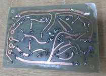
Firsty, I found that the Protection Zener Diode named as D23 was Short Circuited in both channels, no suprises here. Looking Further, I found that One of the NPN Driver Devices, TR10, (2SC2704) in one channel was suspect with a very low B to E Voltage drop, so I replaced it with the same type. To Fool the Va Stage into thinking that the STKs were in place, I made up a small Pcb with some resistors and a Darlington Transistor to take the place of the Input Stage of the STK, in each channel.
After Powering it all up off of my Variac, I increased the Mains Voltage to the correct value and proceeded to do measurements with Meter and Oscilloscope. Everything looked pretty good, so I then mounted one of the Original STK devices on an outboard heatsink and connected it to the motherboard.
Powered her up again on the Variac: Lo and behold, all voltages were almost exactly what the Akai Manual showed. No Sign of Instability at all. Did a Load Check into a Resistor Stack at 1Khz and all looked good.
Then: Inserted a New STK1080ii into the other Channel, and did the same Power up.
As soon as the Speaker Protection Relay closed, The Inner Loop between the
Va Stage output and the input Terminals of the STK went absolutely unstable, looked like bad noise on the scope. No sign of this anywhere else in the circuit, from the preamp stage through to the input of the Final Va stage was clean, even the STK Output Terminal was stable.

There is talk of Counterfeit STK Devices; how is it that the Original STK Device sets up fine, and Yet the New Device is like this? Maybe it is because
the New/current STKs are ALL Counterfeit?

I proved this by swapping the Output STKs between channels; the Fault followed the New One.

Is there any Way I can tame this?

Sorry to go on, but when people are trying to help, it pays to try and be accurate.

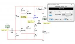
I will have a go to post the Circuit Schematic and Scope results.

Thanks in Advance --

New life for old glorious B&W / ProAC / ESB / JBL and many more....

Hi everyone
I'm Andrea from Italy and I have been passionate about restoration for many years (about 20).
Over the last years I have often worked on old B&W DM6 / DM16 / 802 MS2 / 801 MS2 , ProAC EBS and Studio20, ESB 7/06 7/07 7/08, JBL L300 and many more
and I would like to share my works with you
  • Like
Reactions: diyiggy and Arez

WTB Audio Nirvana Super 3’s full range drivers?

Good morning 😃. Am looking to buy a new or gently used pair of audio Nirvanas super 3 full range drivers in a box of just the drivers. Non smoking environment please. Please E mail me pictures you can. Thanks Jeff


A. Photo 1 has the first version of the super 3’s with a copper dust cap or phase plug.

B. Photo 2 has the 2nd and last version of the super 3’s with a hard paper dust cap and cone revisions to the sides of them.

My E mail Jmboo1922@gmail.com.

Attachments

  • IMG_5739.png
    IMG_5739.png
    1,023.9 KB · Views: 29
  • IMG_5738.png
    IMG_5738.png
    1.5 MB · Views: 52

Tubelab SSE grounding

Hi,

Building a Tubelab SSE and have a quick grounding question. I’ve read Merlin’s chapter on grounding and am wondering the ideal way to ground the power and preamp section.

I’m his multiple star ground section it states to that every smoothing capacitor, all circuitry associated with that capacitor shall be grounded to that star.

My question in the case of the Tubelab SSE is that since the power and preamp section come tap the powers supply at the same capacitor node, should I ground both circuits to the same smoothing capacitor? Or is there a preferred way to ground in amps that the power and preamp section share the same node?

Thanks

First speaker build

Hi to everyone,
I want to build first of my speakers, and plans are for open baffles. I got inspired by Perry's Marshall perception of sound distribution out of the box, and it struck me - musical instruments, or voices, are not directed towards listener, but spread omnidirectionaly, and it's just how our brains posses the sound to give us all the cues by reflections of space. Not only this, but complemented full build plans by Perry, and support provided by members inspired me to build one's for my self. Inspired in such a way, that I couldn't sleep for few nights! ( Flash backs of my childhood memories night before fishing🙂. This time I hope "I'll catch some 🙂

Wanted to aske opinion on FaitalPRO 12FE330 cone driver, as I have found it has nice response, good xmax, weight, and all the rest I don't know what 😂
I want to get those soft rumbles of low notes of piano, and upright bass, and so it can be two per side if needed, or complemented with GRS 15PF-8.
... Wife factor wouldn't approve DSP rout, so passive.
Please join in thought and advise. I would like to invite @perrymarshall as well, so join everyone in please.
Thanks to everyone in advance.

Elekit TU-8200R hum and no music

Hi all!

I have just finished the assembly of my 8200R, I only get a big hum through the speakers even a low volume and no music. I have checked and I don’t see any big mistake. DC voltages are in range although left channel voltages are about 10% higher than right one. I would really appreciate if someone could help me with a similar problem or some hint for troubleshooting. Thank you in advance

Arcam Alpha 9 – Constant Amber LED Issue

Hello guys,

I have a strange issue and I'm wondering if any experts might have an idea of what's going on.

I have an Arcam Alpha 9 integrated amp that plays fine and sounds fine, but its power LED is always amber whenever the speaker outputs are engaged. This happens even when the volume is set to 0 and no music is playing. The amp has two sets of separately switchable speaker outputs, and the LED goes amber as soon as either is switched on—even if no speakers are connected.

According to the manual, an amber power LED indicates one of the following:

  1. Internal protection is on and speakers are disconnected, or
  2. The unit is on mute, or
  3. The unit is overheating or the output is overloaded.
Since I can hear sound, options 1 and 2 are ruled out. Option 3 concerns me, but the unit never gets too hot, even after playing for hours at moderate volume. Should I be worried, or is it likely just an issue with the LED while the amplifier circuit is actually working fine?

Any tips or opinions are welcome. Thanks in advance!

Power Amp Stability Analysis in Older Amps

This post is not how to do stability analysis, but rather did they do a good job of it on these older amps.

==== SOME ONLINE PAPERS AND THREADS
I've decided to add links to some of the papers that we've discussed over the years.
AN2653 from ST Micro on Stability Compensation is attached as a .pdf
There was a lot of talk about "the Gilbert paper" many years ago. There is talk about audio and Otala in this paper:
A member found it online: https://linearaudio.net/sites/linearaudio.net/files/Are Op Amps Really Linear.pdf
Bob C. on how to design MIC compensation:
https://www.diyaudio.com/community/threads/miller-inclusive-compensation-mic-design-example.317147/
Links to discussion about TMC vs. TPC compensation:
https://www.diyaudio.com/community/...tion-tmc-vs-two-pole-compensation-tpc.317330/


==== SOME POWER AMP EXAMPLES
I followed power amp design fairly well through the 60s -90s but didn't have access to many schematics from
Japanese gear so not very familiar with those. I was thinking that there's no clear stability technique used in
many older amps, often caps seem to be sprinkled about in an amp. And why was a Cdom cap so rare, did
they fear that it would harm performance (measurements) or sound? It took a while to think of one amp that
used a Cdom cap, but then of course the RCA reference design (also Harman Kardon Citation 12) came to mind.

==== THE BRUTE-70 FROM POPULAR ELECTRONICS FEB. 1967 BY E. G. LOUIS
https://deramp.com/swtpc.com/PopularElectronics/Feb1967/PE_Feb1967.htm
But let's go back further to the "Brute 70" from 1967, what do you know it has MIC as shown with C4 plus an
output Zobel:
I like this and I hope that it was stable in practice:
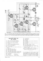
BRUTE 70 PE_Feb_1967.jpg

==== RCA QUASI COMP REFERENCE DESIGN
Next we have Cdom (Miller) compensation, also C4, in the RCA 1969 reference design and a Zobel:
Good job - I built the HK version which was stable in practice.
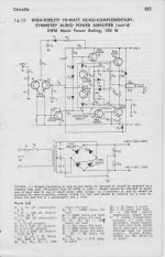
RCA-QUASI-1969-REF1.jpg

==== SWTPC DAN MEYER TIGER AMPS
Everyone has heard of the SWTPC (Dan Meyer) Universal Tiger (UT) 1970 blowing up with lots of smoke:
I don't see any logical compensation scheme here, a Zobel and a cap (C8) on the feedback resistor:
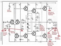
SWTPC-UT-SCH-FIX-sm.jpg

I'll also point out that the Plastic Tiger and Tiger .01 were also prone to blowing up in a similar way with
melted caps.

It seems that Meyer got smart on the Tigersaurus, 1973 that has MIC (C2) and RC (R15 C3) loading on the Vas:
Did he go back and look at the Brute 70 for inspiration? We'll never know.
I built this amp from scratch and it never blew up - nice work.
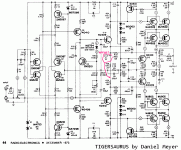
Tigersaurus-Meyer.gif

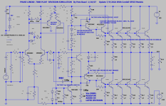
==== PHASEL LINEAR 700 by BOB CARVER 1972
The Phase Linear 700 was the most powerful amp of this time frame at 350W/ch with 100V rail voltages! I was
surprised when I first saw a schematic that it only had 5 output devices per polarity, ten total per channel. After
a lot of thought I concluded that he used some sort of single diffused transistor that were known not to have
(the output are not series connected as was done in most other high powered amps of this time)
SOA issues and would do their rated power at high voltages. He used a Delco electronics XPL909 for outputs
and a guess is that these were developed for the high voltage primary in electronic ignition - a complete guess
on my part. The schematic is essentially the RCA reference design with enhancements as needed for the high
voltage and power. It is a quasi-comp EF triple, how about that? The output current is so high that a triple is
required or at least a good idea. The Vas is boot strapped, probably to avoid another expensive high voltage
transistor. Note the diode protection on the Vas, I'm sure when if these blow up it is an expensive repair so
protection is important. I left out the VI limiting in order to make the signal path more clear. The first version
ran the front end at the full rail voltage, and I'd think that this caused SOA problems in the transistors. He
figured out a clever way to run the diff pair and 2nd stage on 20V supplied by a Zener. This is officially a 3
stage amplifier but the high level of degeneration on the second stage might help in this regard. And, this is
another amp with MIC compensation, a Zobel on the Vas, and a few other compensation networks. It looks as
if some thought went into this design. It does not include an output inductor and I'd expect that capacitive
loads might have given it trouble. Also, without doing the analysis, I'd expect that it would have SOA problems
driving 4 ohm loads, certainly reactive ones. I've seen one in person and heat sinking is quite minimal, fans
that run on temp rise would make a lot of sense. This is redrawn for clarity in SPICE where I chose devices as
close to what was probably used for later repairs at the factory. I am limited to Bob C's SPICE models because
I do not trust others. There are other models checked and fixed by members here but I do not know if every
model in their files have been checked. It does run and the basic operation looks good, I have not checked
for stability:
I know that his later small cube amp had a reputation for blowing up, how about this amp, did it run well at
least into 8 ohm loads?
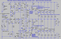
PHASE LINEAR 700B SCH.PNG

==== MARANTZ (DESIGNER UNKNOWN)
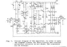
Marantz M510 from 1976 notice C313 and C314 as speed up caps on the emitter degeneration of the push-pull
Vas, C310 across the feedback resistor, Vas loading C312, and diff pair RC damping with C308. This looks well
thought out to me but I have not analyzed it or lived with one - was it stable in practice?:
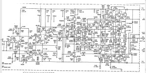
MARANTZ-M510.JPG

==== MATTI OTALA
Here's Matti Otala's (RIP) paper on the theory of TIM distortion Feb 1977, not endorsing this just for historical reference,
note that the schematic for his amp is not in this paper. This paper came later probably to counter the negative
claims toward his work in the early 1970s:
https://hifisonix.com/wp-content/uploads/2017/10/The-Theory-of-TIM-Matti-Otala.pdf

And here is Otala's Feb. 1973 paper with the amplifier schematic:
https://linearaudio.net/sites/linearaudio.net/files/otala low tim amp.pdf

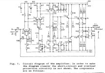
Here's the schematic, note the 3 stages of diff pairs, and C2, C4, C6 as some sort of compensation. R26 and R27 to ground
were a key feature to lower the open loop gain but were controversial. Leach bought into all of this but in the end removed
these resistors from his own designs and employed a Cdom cap. From memory D. Self says, in his book, that he could not
make a 3 stage amp like this stable. I did not hear reports of these blowing up, however note that there's a total of 600mA
in the output transistors make it a very hot amp and there have been reports of burnt circuit boards after 10-20 years.
OTALA LOW TIM 1977.JPG

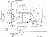
==== AUDIONICS CC-2 BY BOB SICKLER 1977-78
Lynn Olson writes very highly about this design because he worked at the company designing speakers and Bob Sickler asked
him for realistic dummy loads that he could use to test and refine the design:
http://www.nutshellhifi.com/library/bobsickler.html
He started with a Fairchild app note and was influenced by the Otala TIM frenzy. Olson claims 70V/usec slew rate and 60 deg
of phase margin. Olson writes that it sounded good, sold very well, and had a very low failure rate:
Note the use of paralleled driver transistors for higher current and power:
AUDIONICS  CC-2.JPG


==== Professor MARSHALL LEACH PhD
Link to .pdf with Leach's original Low TIM amp article in Audio, and all of the many revisions:
https://leachlegacy.ece.gatech.edu/papers/lowtim/feb76feb77articles.pdf
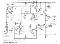
Professor Marshall Leach (RIP) PhD offered a Low TIM construction project in Audio Magazine Feb. 1976 that is simpler,
with fewer stages and more power output: Note that it is quite simple with resistors R20 and R21 to ground at the Vas,
C10 and R33 across the feedback resistor and a Zobel at the output, after the inductor, usually it is before:
LEACH AUDIO FEB 76.JPG

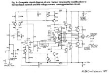
The second part of Leach's article came out a year later in Feb. 1977 with a revision to the schematic, MIC compensation
is added through C10 and R33, interesting. Also, Vas and output protection are added:
LEACH AUDIO FEB 77.JPG

Next we have Leach's Low TIM Amp II in May, 1978, he's moved to Cdom compensation and removed the resistors to
ground and the cap across the feedback network. The Matti Otala features are gone. Also, he's cascoded the input
diff pair transistor and doubled up on output devices - good since SOA was poor on old output devices. Cdom
compensation should be stable but I don't know if he designed the component values correctly:
As Cordell and Self have shown a Cdom compensated amp can have very low distortion and low TIM:
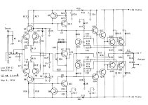
LEACH AUDIO MAY 78.JPG

In Leach's next Low TIM Amp 3, Dec. 1978 we still have Cdom compensation but C11 is added across the feedback resistor,
and capacitors C4 and C5 are added to the diff pair. The main feedback network to the is strange:
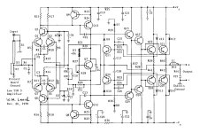
LEACH AUDIO DEC 78.JPG

Leach's Low TIM 4 amp from May 1986, we have the main feedback from the output shunted at HF through C10.
And then HF feedback is provided from the output pre-drivers through C8 and C9. I've never seen this done before,
and I could see that if it had oscillation when clipping due to the finals slowing down, this circuit instead takes the
HF feedback from the pre-drivers. No idea if this was the reason or if it works well:
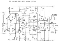
LEACH AUDIO MAY 86.JPG

==== DEAN JENSEN
Save the best for last ...
The JE-990 (990) OP amp from 1980 by the late Deane Jensen is an impressive piece of engineering. He (his company) designed
this, partly, to help sell their transformers. The 990 was first described in 1980 as a public domain design in the AES Journal:
http://www.technicalaudio.com/pdf/J...ted/Jensen_JE-990_opamp_JAES_reprint_1980.pdf
"JE-990 Discrete Operational Amplifier"
JAES Volume 28 Number 1/2 pp. 26-34; January/February 1980

I simulated it here, with links to John Hardy docs and info:
https://www.diyaudio.com/community/threads/simulation-of-the-je-990-op-amp-by-deane-jensen.107404/
http://www.johnhardyco.com/pdf/990.pdf

I read this article back when it first came out and was impressed with the detailed analysis of the entire design but also especially for stability. Circuit simulation was used to optimize for stability:
From the AES article, R9 and C1 provide Cdom compensation with a zero at 8.1 MHz. A capacitor and series RC network across the emitter of Q6 create two zeroes, one at 3.3 MHz and one at 25.4, and a pole at 5.8. Read the article for the full details.
I'm fairly sure that improved stability can always be provided by an RC for the Cdom network and a small cap across the emitter resistor. Of course it will harm stability if they're not properly designed.
This is not a power amp but notice that the outputs below could be the drivers for a pair of output devices. Stability analysis would have to be redone, of course.
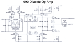
HARDY JE990 2.PNG


I want to add a few others Ampzilla, Marantz M250, and maybe more down the road.
Almost forgot, if you follow the original Leach amp articles in Audio and the follow updates, you'll see that he
certainly didn't get it right the first time and as I recall there were many revisions to the compensation. I
wonder if anyone has the progression of updates documented.

Attachments

Shunt regulator +-15V

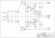
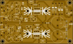
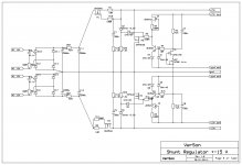
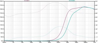
This is quite simple shunt regulator with very low output impedance.
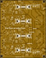
I designed two types of PCB, single shunt regulator and double shunt regulator (in case you what supply for two channels) Output current could be set up to 100 mA.
Damir

Attachments

  • Shunt regulator-sigle-sch.jpg
    Shunt regulator-sigle-sch.jpg
    171.7 KB · Views: 3,775
  • Shunt regulator-single-photo.JPG
    Shunt regulator-single-photo.JPG
    496.6 KB · Views: 3,668
  • Shunt regulator-double-sch.jpg
    Shunt regulator-double-sch.jpg
    186.2 KB · Views: 2,979
  • Shunt regulator-double-photo.JPG
    Shunt regulator-double-photo.JPG
    965.4 KB · Views: 2,847
  • Shunt regulator-sigle-output_impedance.jpg
    Shunt regulator-sigle-output_impedance.jpg
    192 KB · Views: 3,175

Output current of symmetrical / Dual rail PSU using DC-DC converter

Hi,
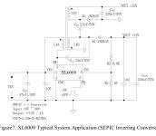
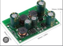
I'm currently looking for DC-DC converter circuit to supply my preamp (+/- 15V) and I found this 2 products on the market. The chip on the board is XL6009 and from the datasheet I found that it's probably done using SEPIC topology.

The board with small inductors rated for 8W max, while the other one with big inductor are rated for 20W max. I have a very minimum knowledge on how DC converter works and the only major differences I found from the picture is just the size of the inductors..

My question is : to increase the output current of the SEPIC topology, is it just as simple to increase the inductor current handling capabilities?

Thanks,
Salwa

Attachments

  • Screenshot_2025-02-23-10-02-08-83_e2d5b3f32b79de1d45acd1fad96fbb0f.jpg
    Screenshot_2025-02-23-10-02-08-83_e2d5b3f32b79de1d45acd1fad96fbb0f.jpg
    81.6 KB · Views: 73
  • IMG_20250223_100301.jpg
    IMG_20250223_100301.jpg
    79.2 KB · Views: 58
  • IMG_20250223_100240.jpg
    IMG_20250223_100240.jpg
    85.7 KB · Views: 63

REW measurements with UCA202

I recently downloaded REW to measure amplifier distortion and speaker FR. I'm using a Behringer UCA202, a pretty inexpensive external ADC/DAC combo.

My first measurements were just some characterizations of the UCA202's baseline noise and my DDS-based signal generator.

Baseline noise:
baseline  UCA202.jpg

There are little blips at 1 and 2 KHz, perhaps some stray pickup from my crappy signal generator:

Cheap sig-gen.jpg

No way I'm using this thing for distortion measurements! Fortunately the output side of the UCA202 is pretty decent. The spectrum below was taken with my JLH-like headphone amplifier:

HA 0dBV.jpg

The peak at 1KHz is set to ~-8dbV because my dummy-load circuit has two 10K resistors to prevent damaging the ADC input. So it attenuates the signal by 8dBV (my measurements determined that the UCA's input impedance is 12K). So the HA's output actually is running at 0 dBV. The first harmonic's amplitude then is actually about -92dBV. Not too bad considering the design's relatively-low OLG. I'm happy about that.

I'm particularly happy about the absence of power line noise in the measurement. Part of the reason may be that I'm using an isolated USB adapter. It plugs into the laptop's USB socket and transfers power and data via a transformer-coupled power supply and isolated data lines -- there's no possibility of a ground loop. The power supply has to be a switcher but seems to be fairly quiet, as shown by my baseline spectrum.

One "gotcha" I discovered while doing the HA distortion measurements has to do with the UCA202's headphone output. I discovered that if it is turned ON there was enough internal crosstalk to cause the amplifier to oscillate. Those limiting resistors paid for themselves right then and there! I'm using two 1/4W parallel-connected 100 ohm resistors to get 50 ohms, close to my headphones' impedance and they got VERY hot, very quickly when the HA was oscillating.

I also have an SAE MKIII C/M that I want to check out. The SM indicates that the output stage's idle current is adjusted so the THD is .03 - .04% @ 1 watt. REW will be handy for that, too.

Celibidache NOS DAC

Orders now are open on Celibidache NOS DACs - PM me and please remember to include your payment method and location so I can quote you inclusive of fees and shipping. Also mention whether you're wanting a kit or a built and tested DAC board. Celibidache is an upgrade of 'Deca DAC' with double the number of DAC chips (20) to achieve lower noise yet keeps the same physical footprint of 100mm * 62mm, the maximum height is 24mm. There's a digital invert function which allows a balanced output DAC to be made from a pair of Celibidaches.

Our preferred payment method is via Wise which typically adds a 2% fee. Our receiving currency is CNY (Chinese Yuan), alternatively USD or Euro. PayPal may also be used, in USD but will attract higher fees, 5.5%.

Price for a Celibidache complete, built and tested : 1080RMB (~$148)
Price for a kit of parts to build one Celibidache DAC : 780RMB (~$107)

Shipping is in addition and depends on your location. Courier - FedEx, TNT, DHL - typically takes 8 - 10 days. E-packet we don't recommend as its uninsured but we'll use it if you're fine with the risk.

If your source isn't I2S, this input board handles other formats (coax s/pdif, Toslink and external I2S for USB) and comes with a screen option to identify the selected source : https://www.aliexpress.com/item/1005002923079600.html?spm=a2g0o.productlist.0.0.4ec6611f1SqyjX&algo_pvid=4d8e6ad6-ba47-4c73-825b-5d2537acb68a&algo_exp_id=4d8e6ad6-ba47-4c73-825b-5d2537acb68a-0&pdp_ext_f=%7B"sku_id"%3A"12000022820866383"%7D

Here's a USB->I2S board (async USB is preferred as its lower jitter) : https://www.aliexpress.com/item/3256802084673395.html?spm=a2g0o.productlist.0.0.3c2471adXUkntw&algo_pvid=8073e594-ca79-46e3-946f-c71fa5fa7ff1&algo_exp_id=8073e594-ca79-46e3-946f-c71fa5fa7ff1-32&pdp_ext_f={"sku_id":"12000019845765273"}&pdp_npi=2@dis!USD!51.29!32.83!!!!!@21365ec216614156405292626eddab!12000019845765273!sea&curPageLogUid=z2efAECosNoh

Technical details

Celibidache runs from a single 24V DC power supply, max current 150mA

Input format is I2S 3 wire (BCK, LRCK, DATA) and 16bits (no MCK required). Nominal sample rate is 44.1kHz though higher rates to 96kHz will work with decreased frequency response flatness.

Max output level as standard is 2VRMS, customization is possible to 4VRMS. Minimum load impedance is 1kohm.

On-board plug-in filter is a modified 9th order Chebyshev giving a relatively flat FR to 18kHz (no NOS droop and no visible 'stair-steps').

Further questions about building a complete DAC and building a kit may be answered in the first post of the Kubelik thread, here : https://www.diyaudio.com/community/threads/kubelik-nos-dac-kits.375955/

The Celibidache kit has the majority of the parts pre-soldered by machine. You can find a picture of the supplied board here : https://www.diyaudio.com/community/...-rbcd-multibit-dac-design.324933/post-6887385 All the 0805 parts (with the exception of user options) are pre-soldered, as are the SOT-23s. Left to solder are various ICs, larger package SMD transistors and through-hole capacitors. The LC filter is supplied as a finished, tested board.

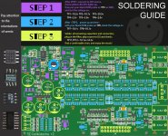
The soldering guide is now attached. Note that some component locations are 'no fit' (NF) which means nothing needs to be soldered there. The '0' resistors on the far right of the board are only to be fitted if you've decided to use off-board output coupling caps. Don't fit them if you're using the on-board Wimas. The default setting of U12 (invert/non-invert) is shown in the guide, that's non-inverting. Fit the resistor to the right pair of pads if you want an inverting DAC.

Attachments

  • _20211121113128.jpg
    _20211121113128.jpg
    167.9 KB · Views: 1,687
  • 20211121113052.jpg
    20211121113052.jpg
    119.9 KB · Views: 1,615
  • 20220121102155.jpg
    20220121102155.jpg
    539.7 KB · Views: 1,108
  • Schematic_Celibidache r2- PXT2907A_2021-12-27.pdf
    Schematic_Celibidache r2- PXT2907A_2021-12-27.pdf
    293.1 KB · Views: 389
  • Celibadache guide r3.jpg
    Celibadache guide r3.jpg
    405.4 KB · Views: 566

LLC Converter Weird Behaviour When I turn up volume on amp to not close to 5 watts.

Howdy,

So I just finished assembling the PCB for this and I am happy to report it does power on and behave like an amplifier. However out of the gates I have found Q13 and Q11 get a bit toasty after a minute or 2, and I am not sure what is going on with my power supply. But with this board when I crank up the volume a little bit. The LLC converter has a spaz and the amp goes into protect. I have an 8 ohm 6 inch driver as a dummy load while I do low power tests, but can't seem to go past 10 watts without something going oh sorry mate the bottom half of the heatsink just fell off and now theres aluminium shrowd everywhere. When I do a power cycle everything is back to normal which makes things harder as I am then not sure if its a short from instability or something. Appart from that when in the "Fault" condition the LLC converter makes a horrific sound then shuts off.
1740118289712.png

SWTPC Universal Tiger Rebuild For Analysis

This thread is to document the rebuild, measurement and analysis of a SWTPC Universal
Tiger (UT) original version amplifier.

INTRODUCTION
There are many threads on here about this amplifier with many members chiming in to write
about how their amp blew up most often with lots of smoke. I built the stereo version at a
young age and blew it up a few years later while using it on the bench to measure speakers.
I've been fascinated all these years by how violently these amps self destruct burning the
circuit board all the way through and melting capacitors. Here's a picture of the typical damage:
790686d1572213744-tiger-amp-madness-uts-top-board-jpg


Schematic: https://www.diyaudio.com/forums/att...096758143-universal-tiger-universal-tiger-gif

These are background threads about this amp, pictures:
Tiger Amp Madness!
General discussion:
Universal Tiger
Simulation:
Swtpc Universal Tiger Improved And Simulation

BEFORE PICTURES
This is the before picture of the amp that I'm rebuilding:
792994d1573146178-swtpc-universal-tiger-rebuild-analysis-utr-1-jpg


Part way into it:
https://www.diyaudio.com/forums/att...pc-universal-tiger-rebuild-analysis-utr-2-jpg

AFTER PICTURES
This was the MKII version but I want to start with the original version since they all need
fixes to cure the oscillation problem. I'm using a home made board, by Tubelab, that has
never been powered up with all new parts. I diode tested all the semis and caps and tried
to use SWTPC parts as much as possible. This is built completely stock but R12 and R14
are upsized to 2W and the rest of the 100 ohm resistors to 1W flameproof since we don't
want the amp burning up during test. Polystyrene caps C3 and C4 are repaced with
ceramic disk so that they will not melt. The feedback cap and input filter cap are on stand
offs so that they can be easily changed for experimentation:
https://www.diyaudio.com/forums/att...pc-universal-tiger-rebuild-analysis-utr-3-jpg

Backside:
https://www.diyaudio.com/forums/att...pc-universal-tiger-rebuild-analysis-utr-4-jpg

Completed amp:
792998d1573146178-swtpc-universal-tiger-rebuild-analysis-utr-front-jpg


Wires are long enough to lay heatsinks flat and raise PC board up for easy access to both
sides. Small C-clamps are used to stand up the PC board:
792999d1573146178-swtpc-universal-tiger-rebuild-analysis-utr-2-jpg


A few more pictures:
I color coded the wiring:
red B+
black B-
green ground
white Bias
yellow input/ output
https://www.diyaudio.com/forums/att...wtpc-universal-tiger-rebuild-analysis-utr-jpg

https://www.diyaudio.com/forums/att...universal-tiger-rebuild-analysis-utr-left-jpg

INITIAL TEST
I brought the amp up on a lab power supply, initially at +/- 28V current limited to 150 mA, it worked
fine, then to the stock +/- 42V also current limited to 500 mA. There was zero bias current in the
output stage and .32V, yes that is V of output offset. I added a bias pot and it was erratic, smooth
up to about 60 mA then jumped up to 350 mA - not a good sign. Left the bias at 50 mA but it did
not help the DC offset.

There are many ways to make the amp oscillate, and turning up the bias was one, luckily having
the power supply current limited to 500mA saves the amp from self destruction and allows
observation on the bench. The 3-5 MHz oscillation is mostly filtered out by the output inductor -
circuit should be probed just before the inductor to see the oscillation.

Thought about this a bit and we might noticed that the feedback resistor is 2.2K but the main input
to ground is 20K. Grounded the input, also for 2.2K to ground and the offset fell to .008V, much
better and agrees with theory. The feedback impedance should be raised and the input AC coupled
in order to keep the output DC offset low.

A FEW NOTES:
1. The output inductor measured 2.3 uH and .067 ohms DCR, it would be better to
have half or less DCR.

2. Most of the 70s UT used mica insulators that I measured as 2.5 thou thickness, there
are many comments about how 1 thou is better. I've seen a repaired UT and a Tiger
.01 with Kapton insulators that measure 2 thou thick, 1 thou is better.
Keratherm products are the modern solution but since I have 1 thou Kapton I'll probably
just use that. Link to tech info: http://www.mhw-intl.com/assets/Keratherm_Catalog.pdf

3. The MJ4502/MJ802 TO3 devices from the 70s and perhaps 80s were of all aluminum
construction. There are many reports of these TO-3 devices failing due to the aluminum's
large physical coefficient of thermal expansion/contraction with temperature. The later
TO-3s that I have from the 1990s are steel or perhaps copper base coated - I'm not sure
but they are not aluminum and should be more reliable in situations where there is a lot
of thermal cycling. The original output devices have poor safe operating area (SOA)
compared to modern devices and therefore should be replaced in any Tiger that is used
at high power or into low impedance loads.

4. Simple improvement to the heat sink assembly that my brother and I noticed back in the 70s:
The stock assembly is shown here where it can be seen that the thermal sensor diode and
collector connection are made on the back side where both heat and electrical current
have to pass through the screw and nuts holding in the transistors. The screw head to
transistor, screw to nut, and nut to terminal lug are all non-gas tight connections:
https://www.diyaudio.com/forums/att...ersal-tiger-rebuild-analysis-utr-hs-stock-jpg

We concluded that moving the thermal sensor and collector terminal to under the screw
head was a much better way to conduct both heat and electrical current:
https://www.diyaudio.com/forums/att...iversal-tiger-rebuild-analysis-utr-hs-mod-jpg

I've not done this mod to this test amp but will do it with any other rebuilds that I do.

GROUNDING:
The grounding is somewhat convoluted in the Tiger amps and documentation
is provided below for others to follow along.

There are 5 terminal points that use chassis ground in the UT mono
block version, the stereo version is very similar:

1. Diode Term Ground:
This is at the bridge diode terminal strip on the mounting terminal
that grounds the transformer center tap and the speaker terminal gnd:
https://www.diyaudio.com/forums/attachment.php?attachmentid=798553&d=1575055539

2. Emitter Term Ground:
This grounds the output transistor emitters through .1uF bypass caps:
https://www.diyaudio.com/forums/attachment.php?attachmentid=798554&d=1575055539

3. Zobel Term Ground:
This grounds the Zobel:
https://www.diyaudio.com/forums/attachment.php?attachmentid=798555&d=1575055539

4. Speaker Term Ground:
This is a chassis terminal lug at the speaker output that grounds the .1uF
across the speaker output:
https://www.diyaudio.com/forums/attachment.php?attachmentid=798556&d=1575055539

5. Input Terminal Lug:
The input RCA jack is not an insulated type and the input circuit, hole A,
is grounding to this lug.
No picture

The published schematic freely uses the ground symbol without making any
distinction between chassis ground and other grounds such as the traces
on the circuit board. There are two traces on the circuit board that I'll
call input ground and driver ground. The input ground includes base bias
for the input transistor, RF filter cap (C1), and feedback network ground (C2)
and connects to hole A on the circuit board. Driver ground goes to the hole
with a ground symbol rather than a letter identifying it. There are some
errors on the schematic where, for example, one bypass cap (C7) goes to the
input ground when in reality it connects to the driver ground.

I corrected the schematic to correctly show input ground, driver ground, and
all the chassis tie points as shown below:
attachment.php


Here's the amp under test, HP lab power supply, HP function generator, Rigol Scope:
https://www.diyaudio.com/forums/att...-universal-tiger-rebuild-analysis-utm-lab-jpg

Attachments

  • UTR-1.jpg
    UTR-1.jpg
    139.3 KB · Views: 2,942
  • UTR-2.jpg
    UTR-2.jpg
    169.5 KB · Views: 557
  • UTR-3.jpg
    UTR-3.jpg
    166 KB · Views: 559
  • UTR-4.jpg
    UTR-4.jpg
    108.9 KB · Views: 519
  • UTR-FRONT.jpg
    UTR-FRONT.jpg
    196.8 KB · Views: 2,858
  • UTR-OPEN-2.jpg
    UTR-OPEN-2.jpg
    150.1 KB · Views: 2,678
  • UTR-RIGHT.jpg
    UTR-RIGHT.jpg
    151.4 KB · Views: 497
  • UTR-LEFT.jpg
    UTR-LEFT.jpg
    186.7 KB · Views: 514
  • UTM-LAB.jpg
    UTM-LAB.jpg
    157.7 KB · Views: 521

Why were 80's Snell crossover so big and messy?

Hi Everyone,

I was perusing the internet, and after finding B&W 801 clones on Ali Express I came across a request for help regarding a Snell type D. A 3 way floor stander with a rear tweeter. Never mind why they wanted help, what it reminded me of is just how BIG and MESSY snell crossovers all seemed to be for the era. Below is an example.

I'm wondering if anyone else has noticed this and has any comments. Of course, I'm a fan of those Snells but looking at these now I kind of shiver. What are your thoughts on the driving principles that got the late, great Peter Snell to these designs?

The only other crossovers I can think of remotely like this might be the M&K S-1B crossovers I got to look at long ago.

1740070019933.png

HDMI to AES/EBU

Hi,

Is there a way to convert HDMI Audio to digital AES/EBU?

Yeah, I know it exists a way, with the ARVUS HDMI-2A (which costs a fortune = USD$1.865) and with the Motu HDX-SDi (that requieres a PC for working). I also know a simpler way of having an "all digital" setup from source to reproduction is by having a PC and use a MiniDSP U-DIO8.

First, why do you need AES/EBU? Well, I want to buy HypeX Fusion Amp or MiniDSP ICEpowered plate amps... both have AES/EBU digital input, so it's a great way to avoid the Analog to Digital Converter, but without losing the possibility of using HDMI sources (PS5, XBOX, Bluray, etc.)

But... is there a cheaper simple way?

Would it be possible that I Can use a Blackmagic (or AJA) mini converter to go from HDMI to SDI with 8 channels of audio embedded and then use another mini converter to "de embed" the audio to AES/EBU?

These converters look very well designed, made with PRO market in mind. Also, cost is not that high for used items (maybe USD$100 ea.) , a lot cheaper than get a Meridian Audio HDMI Processor (HD621 or newer)

Hell, one of these converters also offers the possibility to load a "17 point LUT" to the SDI signal, which you can reconvert to HDMI and have it color corrected!

So, what am I missing here? Loss in performance? Jitter? Insane lag and sync issues

It would be great to know your opinion.

NOTE: I understand the audio processing must be done in the source, so output is PCM and I am limited to 8 channels (no Atmos here).

Cheer!

DIY Raspberry Pi Streamer Kit (STEALTH V3)

Clearance Sales!
HKD2800, Free shipping to the following destinations:
1740039862814.png


Hello guys, I am selling a DIY Streamer kit based on Raspberry Pi 4. Please be noted that soldering and assembly are needed (except SMD components). Please also note that the currency is in HK dollar (1 USD = 7.8 HKD). Can ship internationally. Shipping fee incurred depending on destinations.

Powered by three individual LPS, and galvanically isolated from the touchscreen and the Ethernet, STEALTH V3 delivers extremely quiet background, detailed and lively music experience. Among the three LPS, one of them can be configured as an internal power (5V/1A) for OCXO clock, digital / DAC HAT, etc. Or externally for USB devices (5V/1A) such as USB DAC and SSD/HDD. What’s more, it can also be configured as a power supply for an external device up to 15V/1A (to be negotiated).

When configured as an external USB power, the attached USB device is powered separately by this LPS, and the ground is separated from the Pi 4 with a tailor-made 45mH ground choke. The choke can prevent high frequency noise from flowing into the attached USB device from Pi 4 and vice versa. Additionally, the galvanically isolated Ethernet connection prevents common-mode noise from polluting Pi 4 and degrading sound quality. In fact, the Ethernet isolator works better than an electrical – optical converter, it improves the sound quality with darker background, clearer bass, smoother highs and better separation between instruments.

In short, STEALTH V3 = music server + streamer + player + audiophile switch

For more details, please visit the following YouTube demo (subtitle available):

Introduction:
Login to view embedded media
Assembly:
Login to view embedded media

Usage:
-Music server / streamer / player / endpoint
-Supported OS: Volumio / Moode Audio / DietPi (LMS & Squeezelite) / Roon Endpoint
(pre-built images will be provided upon purchase)

Features:
-7.9" HDMI 400x1280 high resolution touchscreen
-Galvanically isolated touchscreen and Ethernet (10/100/1000 Base-T)
-Individual LPS for the touchscreen and Pi4
-Individual LPS for internal HAT, USB devices or external devices (configurable)
-Native support for i-Sabre ES9038Q2M
-Native support for Monalisa ES9038Q2M
-Native support for IQAudio DAC Pro PCM5242
-Semi-native support for Allo Boss DAC 2 CS43198
-Enhanced thermal management

Case:
-Aluminum alloy with CNC machining and laser cut, sandblasted and anodized.
-micro SD card opening at the bottom
-Dimensions: 240(W) x 220(D) x 100(H)
-6 types of back plate options available

Power:
-40VA audiophile grade R-type power transformer with primary shielding
-3x individual high precision, low dropout and large current LPS
-14x Nichicon FW series capacitor array*
-RC snubber networks
-Ultra low ESR, CLC filtering, WIMA MKP10 decoupling

*Upgrade to Nichicon MUSE caps is highly recommended if you are using an I2S DAC

Price:
-Basic KIT (w/o Pi4 or CAT8 cable): HKD2,800

Back Plate Options:
-Generic back plate: +HKD50 (including blank covers and RCA jacks)
-ALLO BOSS 2 back plate: +HKD50 (including RCA jacks)
-IQAudio DAC Pro back plate: +HKD100 (including an adaptor board, RCA and XLR jacks)
-Extra back plate: +HKD150

Other Parts / Accessories:
-Pi 4 (4GB): +HKD450
-Upgrade to Nichicon MUSE Caps: +HKD200
-Monalisa ES9038Q2M DAC HAT: +HKD400
-IQAudio DAC Pro PCM5242 DAC HAT: +HKD230
-SD card (32GB) loaded with OS: +HKD60
-Cat 8 shielded Ethernet cable (0.5m): +HKD80

Frequently Asked Questions:
-Supports Raspberry Pi 4 only (Pi 3B or Pi 5 NOT supported)
-Touchscreen included in the KIT
-Pi 4 or any HAT NOT included in the KIT

Payment Methods:
-PayPal (extra 6% service charge) are accepted

Remarks:
-Starting from 1 Jan 2024, writing of "STEALTH" on the faceplate will be cancelled. However, the writing will be provided upon request.

3 Transistor HP Amplifier with low dist

Formula3HP

Here is an Amplifier using 3 transistors.
It has low distortion.

Gain is x4 which should be good for 32 Ohm headphones.
Power supply could be one LM317 set at 12 VDC.
All resistors can be 0.6 Watt.

Formula3HP

The latest version is in https://www.diyaudio.com/community/...p-amplifier-with-low-dist.359267/post-7055776

Attachments

  • HP-Special-2-Pub3.jpg
    HP-Special-2-Pub3.jpg
    103.2 KB · Views: 6,415

10M45 / 10M90 - Plate voltage confusion

Hi,

I've been searching through threads and trying to figure something out without posting a new thread, but I'm not finding what I was looking for.
I've got a tube amp with a driver made up of a couple triode stages. The first stage is a 6C5G and I'm using an IXYS 10M90 as a plate load.
I've been using this amp for a number of years now and it works great as far as I can tell, just from listening to it anyways.

I popped it open today though just to confirm some measurements as it's been a while since I've done that. So this is what the circuit looks like:

1705637543983.png


There's a 500 ohm resistor and a 500 ohm trimpot in series between pin 3 on the 10M90 and the anode of the 6C5G so I can adjust the current where I want it to be.
So currently the trimpot is adjusted such that I read 7V over the cathode resistor, meaning I have about 4.6mA (7 / 1500) flowing through the tube, which is all good, that's about where I want it.

The only thing that's odd is that I'm measuring 85V on the plate of the tube.
If I look at the datasheet https://frank.pocnet.net/sheets/028/6/6C5.pdf
It seems to me from the characteristic curves that with 4.6mA flowing, and the grid biased to -7V effectively I should be measuring more like 190V on the plate.

I think maybe I'm not understanding something about how the 10M90 works in this implementation.. It sounds great as it is, but I just don't understand why the anode voltage is so low. Does anyone have any insights on this matter?

Princeton Reverb - Distortion at low volume/not decay

Hey guys. I just built a Mojotone Princeton Reverb and it has this very subtle fuzzy distortion at low volumes when the notes are decaying. It's strange because I used metal film resistors and all of the voltages in the whole amp are within less than 10% of the schematic.

The only mods to the stock design are:

Added grid stoppers and screen resistors to the 6V6s
Added switchable negative feeback using the ground switch. Cable is shielded.
470k resistor on the PI grid.

Here's what I've tried so far and nothing has fixed it:

I have pulled the reverb driver tube.
Adjusted the output tube bias hotter and cooler.
Swapped all tubes.
Tried the Paul C mod.
Swapped speakers.
Plugged in the amp in a different building.

My oscilloscope decided to die, so I can't track it down. Does anyone have any ideas as to what it is and what might cause it? Or is this normal and I'm just obsessing?

I'll add that the amp sounds very nice the louder it gets. It's just the very tail end of decays at low volume that bug me. Gets crunchy.

Targeting 20~30hz treatment possible?

Hi all,

I'm currently trying to see if I can target some low frequency bandwidth.

I don't care about things under 20hz, where I can't hear it anyways. But I am curious if it's possible to try to treat the 20~30hz range here. This is a rectangle room, one sub is on the side wall in the middle (takes care of harmonic first order stuff like a champ). The front two subs are not fully corner loaded but they are near corners and pulled out from the wall behind them. I could potentially put some tall treatment stacks behind these front two subs and stuff the corners maybe. The question is... with what, and from the floor to the roof, or any other idea, like rockwool blocks stacked up, or a frame of it, or another material?

JBL MX15 Towers Aligned at Compressor Limits Waterfall.jpg


Very best,

GB for new SilentSwitcher

This is the official 1st group buy of the new SilentSwitcher.

First introduced here:

Details of the design:

Price of the boards is 75 EUR / board + postage. Output connectors and pin headers are included (but not all soldered).

Postage fees per package (end-to-end tracking):
EU: 20 EUR (Finland 7.90 EUR, Estonia 11.90 EUR)
UK: 20 EUR (possible customs fees not included)

For other countries I suggest a registered letter (actually a letter-size cardboard box) which is also 20 EUR (possible customs fees not included). According to local mail office tracking of registered letters varies by destination country.
End-to-end tracking: US, New Zealand.
Tracking outside destination country: Australia, Canada, India, Norway, Switzerland.

Note that package fees do not include insurance if that is required.

Payments with bank transfer (EU only) or PayPal.

I'll copy the unofficial pre-order list from the main thread to the next post.
I kindly ask everyone to confirm their order before closing date 8th of November 2024. Edit the list and add 'x' to your line. New orders are welcome as well.

Please note that there are more "pre-orders" than the existing batch (200). I will order a new batch if the number of final orders exceeds the current batch. This will introduce a delay of few weeks for the "latecomers".

/Martti

GB - ACA Power Supply Filter Kits

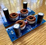
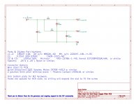
This is a group buy for Amp Camp Amp (ACA) CLC Power Filter PCBs + Parts Kits.

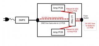
The idea is inspired by the recent Sony VFET P-Channel amp power supply filter. The concept is a low pass filter designed to filter out any hi frequency hash/trash from the SMPS power supply.

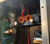
This board is designed to be an easy retrofit/drop-in to the chassis. The mounting holes align with existing slots in the bottom of the chassis. Wiring is also simple. Add a wire from the ground "bus" wire at the back of the amp to the filter board. The red wires from the amp boards get cut. Amp board wires connect the "V+ to Amp" connections. 2 short wires from the switch connect to the "V+ from Switch".

Option A - Stereo Amp Kit - 1x PCB, 2x Inductors, 2x 1000u Caps, 1x 0.33uCap, 8x screws, 4x standoffs
Option B - Monoblock Amp Kit [Kit for 2 ACA Chassis] - 2x PCBs, 4x Inductors, 4x 1000u Caps, 2x 0.33uCap, 16x screws, 8x standoffs
Option C - 1 Board only - good for one stereo amp - you supply parts
Option D - 2 Boards only - good for 2 monoblocks - you supply parts

Group Buy Pricing for kits will be based on the volume of the buy. It's looking like:
5 Option B's (10 total boards including all parts) = $42+shipping per kit
6-24 Option B's = $36+shipping per kit
25+ Option B's = $32+shipping per kit
Divide price by 2 for Option A kits.

Shipping will be appx $4 or 5 in USA. More elsewhere.
Option C = $4 + shipping
Option D = $8 + shipping

Group Buy #1 will close September 17, 2021.
Please make a running list by entering your DIYAudio username and which option(s) you would like. I'll total things up after Sept 17th and order parts.

December 2021 Updates
There was only 1 group buy. You can now get boards fabbed if you like. Gerber files are posted in posts #136 and #137.
Typo on the schematic. ACA uses a 24V PSU. No need for 50V caps. Go for 1,000uF 35V. I used the same series of caps that were called out in the store's P089ZB kit. Nichicon UHW or Kemet ESH series.

Attachments

  • ACA Filter PCB-00a.jpg
    ACA Filter PCB-00a.jpg
    742.1 KB · Views: 2,280
  • ACA Dual CLC PSU Filter-V1.0c.jpg
    ACA Dual CLC PSU Filter-V1.0c.jpg
    561.1 KB · Views: 2,031
  • ACA LC Filter Concept-00a.JPG
    ACA LC Filter Concept-00a.JPG
    53.9 KB · Views: 1,945
  • ACA with Filter-00a.jpg
    ACA with Filter-00a.jpg
    824.5 KB · Views: 1,747
  • ACA with Filter-00b.jpg
    ACA with Filter-00b.jpg
    589.4 KB · Views: 1,681
  • ACA with Filter-00c.jpg
    ACA with Filter-00c.jpg
    50.1 KB · Views: 1,310

Replacing vintage speaker terminal blocks (74mm x 18mm)

I have a Pioneer SA-9500 mkII whose speaker terminals are rectangular blocks, 74mm by 18mm, each holding 4 terminals. Photos below show the Pioneer.

I also have a Sanyo JCX-2600K whose speaker terminals are ALSO rectangular blocks, 74mm by 18mm. Is this a standard form factor? Are speaker terminals with this form factor still available?

It would be nice to upgrade the ones on the Pioneer since they are steel, and steel contributes some distortion.

It would probably work to buy some Pomona dual binding posts, cut a rectangular piece of hardboard, drill it, clamp the posts to it, and affix it over (EDIT or behind?) the rear panel using the same screw holes that held the original terminal blocks. But it would be nice to avoid all that by staying with the original form factor so it looks OEM.

20250222_100308.jpg

Attachments

  • 20250222_100339.jpg
    20250222_100339.jpg
    555.6 KB · Views: 41

Not sure if I can use these

I'm not sure if I have to change anything on the circuit if I use NJW1302G/NJW3281G in place of 2SA1302/2SC3281
Only thing Not sure of is the difference Collector−Emitter Saturation Voltage
2SC3281/2SA1302 Collector-emitter saturation voltage IC=8A ;IB=0.8A VCE(sat)− 2.5 V
NJW3281/NJW0302 Collector−Emitter Saturation Voltage IC = 8A ;IB=0.8A VCE(sat)− 0.4 0.6
Everything else, I think looks ok.
You guys are the experts

Circuit I'm working with is attached
Thanks all
Scott

Attachments

  • Scott.jpg
    Scott.jpg
    170.1 KB · Views: 64

"Compact" 2 or 3-way full-frequency horn speaker

I've seen a number of threads proposing miniature LaScala -type 2 or 3-way horn speakers like below:
1736515620934.png

each one depending on the size of the enclosure has so many compromises that it almost makes it not worth attempting: the performance of the original article hardly inspiring, with a frequency range of 55Hz to 18kHz, reducing the bass bin makes it appreciably worse and many use stock Klipsch components to boot: the K400 mid horn is shouty and boxy sounding, owing to its 1" throat and long throw, while the K-77 tweeter and exponential lens that was used from the 60's into the 80's it sibilant and weak on its best day. Shrinking it all raises the LF cutoff as well as the transfer function of the bass enclosure, which in stock configuration, happens around 110Hz. "Why bother?" was my typical response.

However, I had a stack of wood in my workshop, some spare horns and drivers, going into a long winter without any projects; owing to the success I had with my passive radiating, La Scala-inspired 3-way that played from 20Hz to 20Khz left me wondering if I couldn't build a better mousetrap?

So I got out my calculator and settled a 80% scale version of the LS, measuring approximately 19-1/2" x 19-1/2" by approximately 34-36" tall, with the upper enclosure coupled to the doghouse of the bass bin with a pair of 6-1/2" alloy-cone passive radiators, for a cabinet displacement of 4.5 cubic feet. The objective is to tune the enclosure from 32Hz to 20kHz. Since it's an 80% scale enclosure, it's a simple matter to adapt my existing cut sheets to work. The plan is to build one enclosure as a proof of concept and

I've begun with the LF enclosure, starting with the doghouse:
1736520325211.png

1736520355180.png


the scaled down version will use a 12" 8Ω driver, as opposed to the 15" JBL2225H used in my large 3-way, with a cabinet volume between the doghouse woofer enclosure and the coupled upper enclosure going in at approximately 4.5 cu ft or 127L. I've made multiple motor boards for the upper enclosure, allowing for either a 2-way or 3-way alignment, with the PRV WG4550 mid horn and a P Audio/Lase BD-M750 for two-way, or the same wave guide and PRV's D2200Ph driver and an elliptical tweeter lens with a B&C DE-10 driver up top in 3-way configuration, both crossed over at 500Hz, as the large horn seems to lose directivity below 475Hz. and either a passive network, Dayton DSP-408 active crossover or a combination thereof:
1736521397601.png

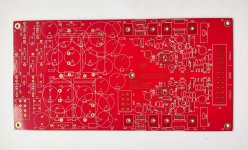
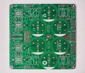
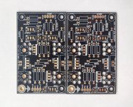
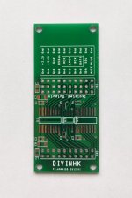
** PCB surplus **

SOLD

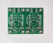
I went through my drawers or boxes respecitvely, and found a good number of pcb's for projects that will never see the light of day.
All absolutely unused and safely stored...

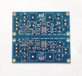
- one pair of Jan Didden V2.2 superregs

- one pair of Salas' SSL1.1 Back in Black

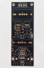
- one Salas SSHV2 High Tension shunt reg

- one pair of Per-Anders 'Ultra High Performance Regulated Power Supply' SSR03 Rev. 0

- one pair of Prasi's CRCRC PSU for Class-A Amps

- one pair of Linear Audio Treg TS-3, with some soldered components (by vendor!) and a few parts

- one pair of Gluca 'PCB for cascoded IXYS CCS'

- one pair of LT4320 active bridge controller

- one DIYINHK isolator

I will ship these around the world if so required. Shipping to the EU and the US and Asia as big letter is between 2$ and 4$.
For prices please inquire via PM, I lost track of the individual prices (will be reasonable 😉)

Attachments

  • 1740217992468.jpg
    1740217992468.jpg
    459.3 KB · Views: 250
  • 1740217992474.jpg
    1740217992474.jpg
    249.2 KB · Views: 77
  • 1740217992477.jpg
    1740217992477.jpg
    503.9 KB · Views: 73
  • 1740217970502.jpg
    1740217970502.jpg
    457.1 KB · Views: 71
  • 1740217970505.jpg
    1740217970505.jpg
    381.4 KB · Views: 73
  • 1740217992460.jpg
    1740217992460.jpg
    364.3 KB · Views: 80
  • 1740217970507.jpg
    1740217970507.jpg
    621.6 KB · Views: 81
  • 1740217970509.jpg
    1740217970509.jpg
    481.3 KB · Views: 83
  • 1740217992464.jpg
    1740217992464.jpg
    205.4 KB · Views: 80

what is the difference between the audio data interface formats? (MSB FIRST, LSB FIRST, I2S, etc...)

what are the formats that are used? how to distinguish between them? can sometimes two different names or designations mean the same thing?

I want to change the cs8412 and df1700 in my dac in favor of a wm8804 input receiver and df1704 digital filter, I found a few modules that use those two chips and claim to be able to replace the cs8412 and df1700.

after diving into the data sheets of the df1704, I noticed that it has no "MSB first two's complement" input like the df1700 it is supposed to replace, but it does say that is has sony standard, is it possible that the sony standard is the same as "MSB first two's complement"?

Guitar Vocoder Pickup System

Interesting what can be built within the singlecoil pickup dimensions these days; https://www.audiospektri.com/pgv-micro/

Processes each string individually, without the hassle of an additional six-channel cable from the guitar to box on the floor. Play a 4 note chord and it vocodes your voice against each string individually, so it sounds like 4 of you in vocoder harmony.

1739996688968.png

Anyone still remembers the Philips 9710M?

The title probably gives something away about my age.

Always been an enthusiast of the Philips full range drivers, despite their shortcomings.

After years listening to a small transmission line box (design P.Atkinson 1978!! see enclosed PDF) I found its time for a new adventure with a modern full-range system.

Have been reading a lot about the Frugal horn (lite), but not sure if the size would fit my situation.

Looking for small, but with good bass... aren't we all 😉

Greetings from Portugal

Attachments

FRED / Stealth rectifier diodes

Some time ago the use of Fast Recovery Epitaxial Diodes (FRED, e.g. Fairchild’s “Stealth” diodes) were popular here to minimize switching noise from the PSU in the audio system. Low reverse recovery current and extremely soft recovery apparently are features that did the trick.

I’d like to try in some projects, most notably a phono preamp and a power amplifier.

I wonder about the power ratings of these devices though. Clearly they were designed with quite different applications in mind, most notably hard switching, high frequency stuff like flyback diodes and other switching power supply applications. Not the kind of linear PSU that I’m thinking of.

Power ratings of these tend to be high (but appropriate for the intended application): starting at 300V or 600V and current ratings ranging from around 10 up to several tens of amps. Compared to these ratings, the actual power consumption in my projects are negligible, virtually zero. Especially in the phono preamp.

When choosing these devices for a linear PSU for audio applications: does the power rating matter at all? Or is it entirely irrelevant? Would it make no practical difference choosing a 30 amp unit over an 8 amp unit?

Onkyo CR-725

My problem is an ONKYO CR-725. Power supply ok. But except that i have no words. What a mess! Pictures speak for themselves. Someone really messed it up. It seems they bridged something. I would kindly ask for the value of q941, c941, r941 and d941. A service manual or schematics for CR-725 would do miracles. Thank you very much.

Attachments

  • 20250209_123522.jpg
    20250209_123522.jpg
    361.1 KB · Views: 93
  • 20250209_123532.jpg
    20250209_123532.jpg
    393.6 KB · Views: 85

QED A240CD Amplifier - Buzzing Through Speakers Even at Zero Volume and Strange Behaviour

I've recently completed some work on my QED A240CD amplifier, replacing some capacitors and transistors. This included the 2 filter caps. I now seem to have a strange issue where my speakers are buzzing even at zero volume. I cannot hear any sound coming from the amp itself when speakers disconnected. It seems to be an intermittent 'fault' because yesterday I played music all day with no problem. When it occurs it affects both speakers. The weird thing about this is that when I either hovered my hand over the internals or lightly touched the outer casing of some of the capacitors the buzzing would stop. The lid was not fitted at this point so I thought that maybe the lid needs fitting to maybe 'shield' or 'deflect' any external interference. It in fact made it worse. I only had to hover the lid over the top of the amp and the buzzing would get worse. My suspicions are perhaps some earth fault but I'm aware it could be caused by earth loops, cable placement or having the equipment close to external electrical interference. I've tried moving the amp well away from other equipment and ensured cable routes were good. The amp has always been plugged into the same wall outlet as other attached equipment. Anyone have any ideas what could be causing this strange (but true) phenomenon? Thanks, Andy
DC Voltage Rating for Ceramic Caps passing Large AC Voltage

Hello!

I am trying to figure out what DC voltage I should be rating a 0.1uF C0G/NP0 for a hum block circuit like the Valve Wizard has put in his amp grounding pdf (page 15). The capacitor is between the circuit ground and chassis ground. It isn't that easy to find out what DC voltage rating you should be using for AC signals - Kemet has a pretty good page on how it suggests you approach AC voltage on their DC rated ceramic caps.

I'm not really sure what the appropriate voltage rating for a capacitor in a hum block network would in be in, say, a power amp with 30V +/- or even 100V +/-. I'm imagining that most of the signal current present would return to the transformer windings, leading to a limited voltage difference across the terminals of that cap in the hum block, but maybe my mental model is wrong. If I am wrong, then Kemet's document would be suggesting some pretty high voltage ratings for the cap, in which case I would turn to polypropylene film caps.

Thanks for any advice.

Panasonic mini speakers 2-way crossover mod (with measurements)

Hello! Usually this question regarding upgrading cheap speakers gets asked a lot and as a somewhat more experienced DIYer I know there's never a precise answer without having a proper testing procedure to back it up.

However, I have a measurement microphone and made myself a DIY impedance measurement rig, so this time I had a way to measure the drivers that are part of the Panasonic SB-PM01. It's a 2-way bass reflex mini speaker with a 4" midwoofer and a 2" cone tweeter.
I want to improve this very basic pair of speakers for a fun project.
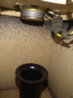
The speakers and the drivers themselves look pretty nice, the box is also very sturdy, the bass reflex pipe is tapered both ways. There's no sound deadener in it.

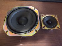
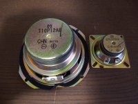
The drivers have an "M" logo stamped on them and the part numbers, which is T10P12A6 for the 4" woofer and 6PH322A6 for the 2" cone tweeter.

The original measured response doesn't look great, it's tilted up by quite a lot and there are a lot of peaks and dips especially in the midrange. My explanation is that because the midwoofer has no crossover, and the tweeter only has the typical 2,2uF NP protection cap, they overlap by quite a lot in the midrange causing all sorts of phase issues. This is confirmed by the fact that the off-axis response is much worse.

So, my plan for these speakers is to use them to make a decent sounding pair of speakers, starting by a new crossover which will improve the midrange and the soundstage and then adding some deadener which will take care of that 150Hz peak.

I measured the woofer, then the tweeter, and then both of them in parallel to get the z-axis offset right.

I think I made a pretty decent crossover in X-sim. The response graph looks pretty nice and the impedance graph drops down to about 3,34 ohms at 5,5kHz. This shouldn't be an issue with most modern amplifiers.

Here are some pictures of the drivers and the measured response of the speakers as they came from the factory (scale is 10db/div):
PANASONIC FR BEFORE.jpg


IMG_20220808_183005125.jpgIMG_20220808_183015313.jpgIMG_20220808_164419995.jpgIMG_20220808_164409975.jpg
This is a screenshot of the crossover project so you don't have to download it in order to see it (the scale is 3db/div):

Screenshot (42).png

What do you guys think of it? Do you think it can be improved?
I'm attaching the project files.
Thanks a lot!
  • Thank You
  • Like
Reactions: sgrossklass and GM

Differences between THAT 1206 and 1246

I can see from the data sheets that the 1246 seems to have better ESD protection built in -- its datasheet does not ask the designer to add all those zener diodes before the inputs.

Other than that, what should be the factors based on which I should select one? I want to build an active xo circuit, which will accept a typical signal between, say 50mV and 2V, from the upstream device over a distance of 5-10 feet. The output of the line receiver will drive 2-3 opamps, maybe 3-6 kOhms of load.

Attachments

Ultra low noise pre-amp for low impedance sources.

For noise spectrum measurements like PS, references, batteries etc.
Gain 60 dB, bandwidth 4 Hz- 500 kHz (GBW - 500 MHz), noise below 400 pV/sqrt(Hz).

Inspired by:
http://www.dicks-website.eu/low_noise_amp_part3/part3.html
https://www.diyaudio.com/community/threads/ad8428-low-noise-preamplifier.407270/page-3#post-7910879
https://keith-snook.info/transistor-noise-and-rbb.html

Choices made.
-no extra large electrolytics, so no DC NFB, just auto bias;
-single power line, common LM317 regulated (noisy) power source;
-no expensive electronic components.

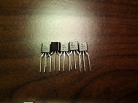
Transistors:
2n4401 pics.jpg


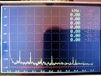
Results:
-120 coresponds 1 nV.

2n4401-a.jpg

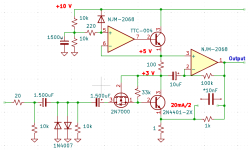
Schematics:
Low noise pre-amp.png
Circuits description:
TTC-004 is a denoiser/ PS ripple suppressor.
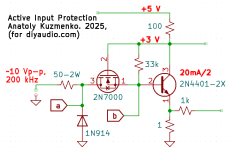
2N7000 is active input protection - saves BJT during input conection/ disconnection
overstress.

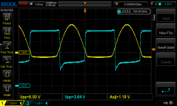
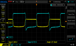
Real crash test of input protection:
Active Input Protection-b.png

yellow - base voltage, blue - collector.

prot_10Vpp_R50a.pngprot_10Vpp_R50b.png

Silent & noisy grounds on a RIAA preamp

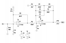
I am modifying a phono preamp kit to adjust it to a design of my own that we discussed some time ago on a thread here on this forum.

My concern is how to separate the silent and noisy grounds in the schematic to send them separately to the star ground.

How should I proceed?

My first idea is to isolate the input ground with a 10R resistor, but I am not sure about the gain and filter grounds if they should be isolated too from power ground.

Attachments

  • EB_LT_1792.jpg
    EB_LT_1792.jpg
    40.2 KB · Views: 450

Misophonia

I've just discovered I have Misophonia It's pretty common, I'm relieved to know; supposedly something like 1 in 5 have it, so I guess many members of DIYAudio might also suffer this ailment. To save you looking the word up to find out what it means, it is the hate or disgust of certain sounds, especially eating noises. It was triggered again yesterday so I did some Googling on it and pleased to find out I'm not the only one. I was also thinking that our passion of loving music and purity of sound could even mean we have a bigger proportion than average. I list the ones that make me explode with anger and makes me want to scream SHUT that ****ing noise. I find it hard to really give them any order of intensity of the annoyance ...They really are nearly all the same to me. So, I start with the most recent one:
1) People scraping out plastic/paper yogurt pots when they're nearly empty. That little tap-tapping sound as they search around and around with the spoon, looking for the very last molecule of it, makes me go nuts!
2) People who have transistor radios on at work in the office, on the beach or a neighbour in the garden, nearly all are tuned to utter modern pathetic crap pop music. It's even worse when I can only just hear it too. Maybe if it was blaring out loudly, I could stand it more? ...Hmmmm maybe not!
3) People whispering on TV or radio ads or films. That breathy-over-loud- unnatural sound makes me want to scream. You know the type.... you can actually hear the lips moving...UGGGGH!
4) More commonly, people who smack their lips when they eat, I guess this must be very common with people.
5). Oh yes, just thought of another one....In the UK it has now become trendy to miss out the letter T when pronouncing any word that contains it midway in the word... This insults me so much in that the utter, shear, low-life, ignorance of the person speaking has actually entered my brain via my ears!

Anyway, I would love to know what other sounds get people angry to the point of rage. It could be quite funny, I think.

The Grace digital radio - Capitalism as its finest

Picked up a "Grace" digital internet radio yesterday, when it powered up and I connected to my router, I expected it to "just work" like the Logitech radios I've found. Come to find it's truly trash, by design. Apparently this radio is wholly dependent upon the existence of some "3rd party service provider" and during some corporate shuffle, that went away. So all the radios built in this way are hence, trash.

It's hard for me to imagine building something in this way... Planned - or unplanned - obsolescence. Whomever took the money and ran, should be obligated to "clean up the mess" as a cost of doing business in such a way - hard coded. Apparently, adding the functionality to allow entering an ip address, assigning a button to that and connecting to the "stream" of that ip was too difficult to have as a self contained function. No, it has to connect to the server somewhere to handle that.
Personally, I put that well into the category of "dirty pool". Maybe next is your car, when America cuts the internet to, say, outside countries, it just stops working. Too bad - you get the service from it you got.

I paid <$5 for it at the Thrift store. It's certainly not the money spent for the privilege of disposal; it's what the construction represents that I find abhorrent. The endpoint, still electrically working, but useless. I was mostly hoping to use it for an assumed internet connected nightstand clock, but it wouldnt even provide that for me. I had no idea of the situation when I picked it, mostly because it's simply beyond my imagination someone would build such a thing that way.

I read where people have made tremendous effort to get such radios working again, I assume driven by the energy of being so pissed off about it. One involves reconstruction of the server locally, but I believe you'd have to have done it before the online service shuts completely, to get the station buttons defined.

C'mon... Could they have deigned it any worse? No "healthy" shame, apparently.
  • Like
Reactions: Freedom666

For Sale Wayne's Burning Amp 2018 Linestage

SOLD!

PSU can be easily converted to 115V.
  • DiyAudio Store PCB, capacitors and active parts (USA)
  • Helios bi-polar CRCRC regulated power supply (UK)
  • PSU Panasonic low-profile capacitors and power resistors (Mouser)
  • Talema transformer (RS Components)
  • Dale CMF55/RN55 resistors (Mouser)
  • Original 20K Alps RK27 potentiometer (RS Components)
  • GlassWare Select-2 input selector (USA)
  • PTFE wires and gold-plated RCA connectors (China)
  • HiFi 2000 Galaxy GX347 330 x 170 x 40 mm chassis (Italy)
  • Stainless steel M3 screws and brass spacers (China)
  • Keystone Thermoplastic Elastomer Feet (Mouser)
  • Front panel engraved plastic labels (Sweden)
  • Solid anodised aluminium knobs (China)
Ask if I missed anything.

Attachments

  • 2022-09-24 09.10.35.jpg
    2022-09-24 09.10.35.jpg
    639.3 KB · Views: 195
  • 2022-09-24 09.13.04.jpg
    2022-09-24 09.13.04.jpg
    653.3 KB · Views: 188
  • 2022-09-24 09.14.39.jpg
    2022-09-24 09.14.39.jpg
    571.4 KB · Views: 165
  • 2022-09-24 09.21.42.jpg
    2022-09-24 09.21.42.jpg
    777.1 KB · Views: 155
  • 2022-09-24 09.22.03.jpg
    2022-09-24 09.22.03.jpg
    721.2 KB · Views: 146
  • 2022-09-24 10.47.49.jpg
    2022-09-24 10.47.49.jpg
    223.3 KB · Views: 154
  • 2024-03-09 10.56.21.jpg
    2024-03-09 10.56.21.jpg
    169 KB · Views: 160
  • Linear-Reg-PSU-LM29xx-1024x643.png
    Linear-Reg-PSU-LM29xx-1024x643.png
    216.1 KB · Views: 181

Eminence Kappa 15C Pair

I have a pair of like-new Eminence Kappa 15Cs in original boxes. I bought these new in summer 2024 and loaded them into a pair of DIY LaScala clones that... sigh... didn't get wife approval.

Both drivers have maybe 2 hrs on them. Bought new from PE for $180 apiece, asking $250 for the pair. If you're near Denver and willing to be a little patient I can bring them to you, otherwise request buyer pays for shipping and I'll follow your lead on carrier.

IMG_4048.JPG

Castle Severn 2 Speakers

Hello,

I joined the forum as had been doing some research into my set up. Another member was refurbing some cabinets for Castle Speakers and was asking about the downward bass port (I’m unable to reply to that thread). I never knew there was such a thing as when I bought mine the plinths were attached directly to the speaker cabs. I love the sound of this set up, extremely articulate with great vocals and lovely warmth but always did lack a touch of bass at the low end. I’ve now released that bass by putting spacers in and wow! Now having to listen to everything again! Photo attached of the aperture for that chap if he is still looking to recreate.


Cheers


IMG_0824.jpeg
IMG_0831.jpeg
IMG_0832.jpeg

SMD Soldering Basics

With so many projects containing SMD components now I feel compelled to try and gain the skills to do some basic stuff.
The (I'm an accomplished solderer with normal THT stuff) only problem I have is I'm joining the game a bit late (64 years)
and the vision is fading a bid. After reading an article I'm wondering is something from AmScope might be the answer?
AmScope

Regards,
Dan

BC horn inspired "HBH15"

Hi all! I recently saw this post from @All_1 which prompted me to finally make a write up on this project. I started this over in the Speakerplans forum during Covid, but only recently managed to finish a build. I wanted to hopefully consolidate our knowledge on how to effectively sim boundary/baffle coupled style horns.

I've only had an hour to put sound through it, and got just one quick and dirty nearfield measurement so far. My laptop was then stolen so I lost some sim data and the measurement barring a few screenshots. I'll have more time in a few weeks which should hopefully include some outdoor measurements. Here's the build:

IMG_9959.jpg


Here's the measured vs simmed response:

IMG_9791.JPG

IMG_9793.JPG


A few notes. I suspect the nearfield measurement is coloring things, hopefully making the response appear more like a 2pi measurement but tbd. Even so, a close response. The main thing for me was making sure that low corner was in fact there, since in Hornresp this required some guesswork (looking forward to diving more into this). The panel that's ratchet strapped on would start resonating like crazy at a certain point as well (I guess more reason to build the second soon) which more than likely also colored this not quiet measurement (UMM-6 tops out at 120dB I believe).

Here's the group delay measurement vs response:
IMG_9792.JPG

Screenshot 2025-01-27 164121.png


As for subjective notes: I'm very happy so far, but much more testing to be done. The room I have this in is big with a tall ceiling, but the nearfield was a pleasant and "tight" massage. I'm starting real small and just have a 450 watt amp, but I was barely seeing the signal light. Simmed response suggests this cab will hit xvar at around 900watts.

I definitely want to shoutout everyone over in the speakerplans forum, especially Jo bg and citizensc for humoring my ramblings and running some great Akabak sims that convinced me to cut some wood and chance it, and all those that started threads here in diyaudio. I also need to thank several local sound crews in Seattle for their input (Milestone Productions and another crew to emerge soon...) And of course Tom Danley for all the inspiration and for creating this type of design (Lambda Labs Digital horn also deserves a shoutout, although I believe it's kind of a TH version of this). Oh and of course David McBean for creating Hornresp!

Let me know what y'all think and if you have any Qs. Hoping for more measurements soon.

OK, but HOW does it sound? BA3 Bal / Bridged F4s vs XA252 MOSFET

BA3 Bal / Bridged F4s vs XA252 MOSFET

So, so much discussions about components, bias adjustments, color of the LEDs, twisting or not twisting wires, noise, boxes, heat, overheat, etc, etc...

But at the end of the day, assuming nothing smokes, shorts, sparks, capacitors don't dry out in 20 years or the Sun doesn't go nova on us.....

... we sit down to listen.

So, how do the amps sound?

Most of the time, people tend to just listen to the amp.... and enjoy, but sometimes, well, you got two amps, or variations of an amp, and you think...

HMMM, which sounds better?

And, then... what if I were to mix and match? Hmmm......

+++

I recently received my XA252 base amp, the one with the MOSFET pucks, it replaces the problematic 252SIT... and I was asked to compare the sound of the 252 with the objects currently on the rack, a pair of bridged F4s with a BA3 balanced... driving the Maggie 1.7.

I compared them by treating the BA3/F4s as a unit. So I moved the balanced interconnects from the Iron Pre to the BA3 or 252. Everything else was the same, source, preamp, speakers, cables.

I also have a memory of how the bridged F4s sound in my little Audio Note speakers.... and how the 252SIT drove them as well. ( I never had the 252SIT on the Maggies). More on that anon.

So, how did the amps sound on the Maggies?

BASS:

The BA3/F4s have bass slam that needs to be heard. There's is true impact to the bass, it is quick, articulated, fast. You can feel the notes being plucked and the waveform being launched from the speaker. It feels like a subwoofer is hooked up, but much faster (1). (2)

The 252 do not have that deep bass, nor the control. They have good bass, mind you, but their sound is lean in comparison.

POINTS: BA3/F4 wins. Hands down.

MIDRANGE:

The 252 has a beguiling sound. The voices, the piano feel likes they are in the room with you. You can hear the phrasing of the singer's voice, the piano has beautiful sonority, a richness of tone that is to be heard. So does the guitar, the saxophone... it's all sweet and rich and believable. Not overripe, mind you, the instruments are distinct, separate, the soundstage is exceptional. The depth is a little bit shortened though as instruments and vocals move forward.

Sort of like my tube amp. It's all about the harmonics. Sound you can take to the desert island and not be bothered by any thing else... a Forever Sound. It was a rainy afternoon here in SoCal while I was listening, the tunes brightened up my day considerably.

However, we are never happy, what if? So...

So, the BA3/F4.... well, they are cleaner sounding. The instruments are not so rich. Overtones are realistic. They sound very accurate, the soundstage is perhaps not as deep and the voices are laid out farther back. Most likely they are where they should be, all about the melody, not the harmony. A sunny day after a rainy day...

The BA3/F4 are like a Palo Cortado sherry. Great bouquet, aroma and a dry finish that doesn't overwhelm the rest of the flavors.
The 252 is like a good Cream Sherry or a Ruby Port. Great bouquet and all of that.

POINTS: I just gotta give the points here to the 252. It is a lovely sound. Like an Aleph gone to finishing school.

TREBLE

I gotta say I didn't pay that much attention at this point to the treble. Both amps are airy, with very realistic treble. The cymbals come through cleanly and clearly. The sound is never dark and the treble is never "shhhhh" or tizzy. It is what it is. Good place in the soundstage.

That said, the drum kit, taken as a whole, sounds more realistic with the BA3/F4 because the combination of the bass drum, tom toms and cymbals sounds extremely fast, whole, lively and realistic. It is more what I remember a drum kits sounds like in real life.

But other than that, I think it's a wash.

POINTS: TIE.

DYNAMICS

Here I'm really puzzled. There is something about the 252, in general, that befuddles me. I've had both the SIT and now the MOSFET puck... and both exhibit a strange behavior. They never sound loud enough. Why? In the past I thought such was because an amp lacks distortion and as the volume goes up the sound remains clear; that is, the distortion does not increase with volume. Hmm.... but the 252 definitely has some 2nd harmonic in there, so why is it that with the 252 I always find myself turning up the volume?

I was playing Heart's Dream Boat Annie, the whole LP, and I just had to turn it up to 11... because, Damn!!, the thing sounded SO GOOD.... And at one point I noted that the right channel wasn't sounding right.

I had been forewarned: "Don't blow up this one!" (3)

Well, the Iron Pre Bal has individual pots for L and R... so I turned down the L and sure enough the R channel was not right.... oops.... I turned down the volume and then happiness returned. Nothing blown. The system was playing loud, but somehow it was just not loud enough for me. So I can testify the 252 puck amp is safe(r).

The 252SIT had the same behavior, sort of, but at lower power levels. Except for the catastrophic failures. Hmmm....

The BA3/F4 sounds satisfyingly loud enough. I've had it both on the Maggies and the AN and these babies rock. Not to 11, the Maggie 1.7 never do 11... but they sound as loud as it gets. Indeed, it is easy to overdrive the Maggies with the BA3/F4, you an actually hear it. But, it's not the amp, it's the speaker.

POINTS: BA3/F4. It just sounds faster and sounds... ahem... louder.

CONCLUSION:

It's not a clear cut choice. If we ever get a Biggvs Dickvs SIT from ZM that puts out 100 wpc and doesn't immolate itself when being pushed.... OTH, the bass from the BA3/F4 and its ability to swing from soft to loud and back on the proverbial dime... is SPECTACULAR.

So the choice, to me, comes down between the dynamics or the tube like midrange.

POINTS: no way, I'm not done. I wonder if I could biamp the speakers...


(1) I do have a pair of very fast Entec SW5s, so I know what a musical subwoofer sounds like. They mate very well with Maggies.

(2) Here I must note something. I've played the BA3/F4 into the Maggies and the AN. I also have a pair of A2s on the rack. I swap amps and speakers back and forth. The A2, with more power, do not have the bass drive. The BA3/F4 bass into the AN is rich bass, not overripe but definitely rich and deep. Again, as if someone had turned on the subwoofer under it. However, the A2s are wired singled ended to the preamp, perhaps is this the reason? I should try...

(3) I had two similar encounters with the 252SIT into the Audio Notes. First time smoke poured out of the amp.... after the rebuild, the second time the right channel went dead but not before it smoked the voice coils in the woofer. The technician stated it was DC.... That why I was warned not to "smoke it" again.

Attachments

  • 20250125_154524.jpg
    20250125_154524.jpg
    489.1 KB · Views: 494
Projects by fanatics, for fanatics
Get answers and advice for everyone wanting to learn the art of audio.
Join the Community
507,685
Members
7,884,222
Messages

Filter

Forum Statistics

Threads
406,035
Messages
7,884,222
Members
507,685
Latest member
EvenLouder