This is the description of a simple fullrange and fast 3d construction technique, and also of applying DSP (by CamillaDSP) for frequency equalizing and interchannel crosstalk compensation.
Intro:
I do not like the performance of average, small PC desktop speakers. Neither do I like to clutter my desk with fair sounding, but, for a desktop, rather huge standard HiFi loudpeakers. And I do not like to spend as much as a pair of small genelecs would cost.
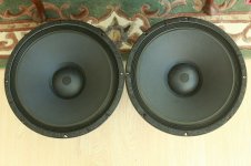
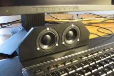
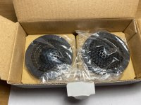
But then, I had a pair of spare Vifa Ne65W drivers. Along with some bit if corian board, I built a small, «fullrange» stereo dipole array, knowing that the performance would be very limited in terms of SPL and lower frequency range extension. And with a stereo base of 7cm, they would neither project an impressive, 3D stereo landscape. So, this small speaker was not intended for serious audio. but more so to be small and also optically to match the monitor design, and last not least, to resproduce some of the audio signals potentially emanating from the pc once in a while in a better than desastrous quality. No more. And no less. And this is what I need most of the time, when I am confronted to a PC sounding.
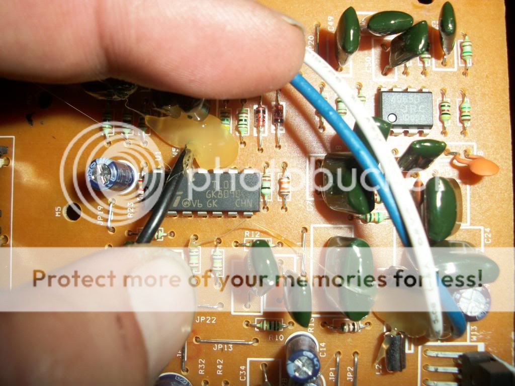
1.jpg
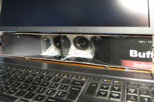
2.jpg
However, from time to time I wanted a slightly better audio than that, e.g. for music flics on youtube or the like. But still, I did not want to add further electronics gear onto my desktop. So, what to do? I decided to go for a solution à la convertible.
Construction:
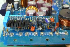
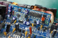
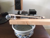
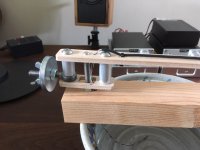
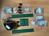
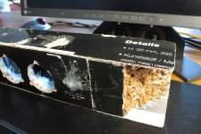
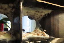
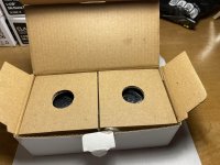
Having some cardboard boxes (a leftover from a recent LED-Lamp buy branded «BUFFY Indoor»), I built some kind of a horn addon box, along with hot glue rods and hydroculture burnt argile speres. It was quite fun how quickly its rough structure could be assembled. As cardboard is very resonant, I filled all spaces with layers of hot glue and expanded argile spheres. Also this procedure is a very fast and simple, straightforward and iterative process: Disperse hot melted glue, pour a handful of spheres onto it, squeeze it a bit, then pour the non-adherent speres away/out. Then again disperse hot glue on this newly applied spheres layer again, pour handful of speres onto it … The glue and speres block gets quite rigid. The surface of the last, upmost layer might be soaked and brushed with white glue for wood bonds, in order to seal the whole thing. What finally came out, I called it a BUF Indoo. Don't ask why ...
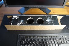
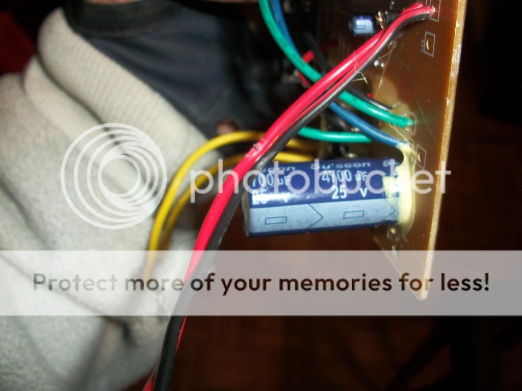
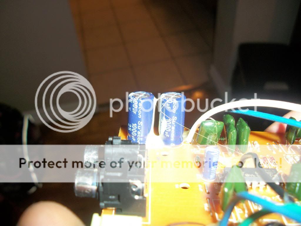
3.jpg
4.jpg
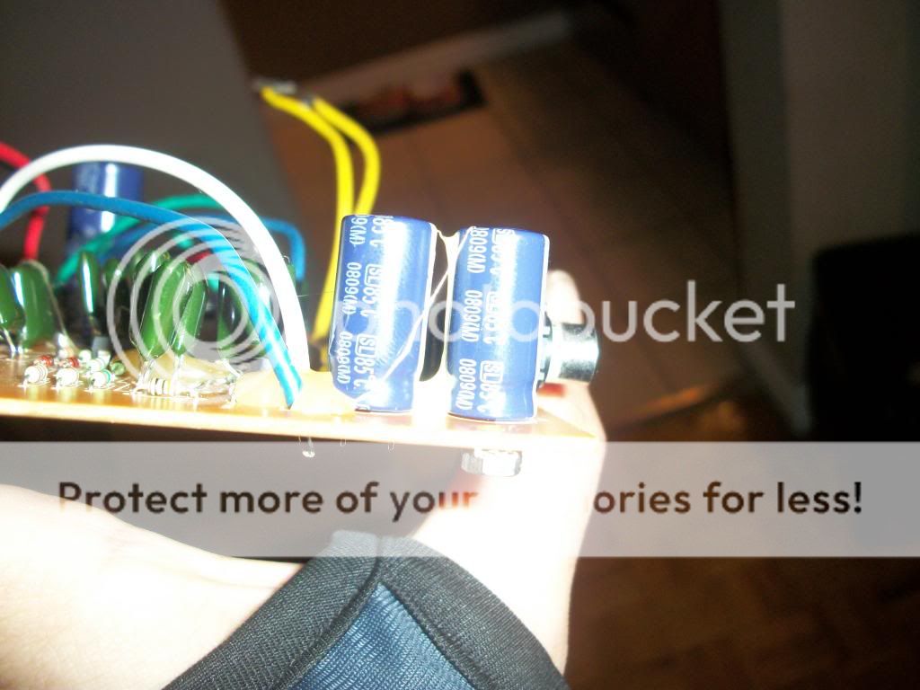
5.jpg
6.jpg
Acoustics and measurements:
Now, how does this BUF Indoo behave acoustically? Lets see … Roughly, the desktop and the monitor provide a small pi/4 – space, along with the BUF Indoo radiating out of the corner line. Therefore, desktop and monitor might act as tow faces forming a semi-horn. Semi, because the sides of this semi-horn are left open.
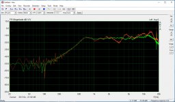
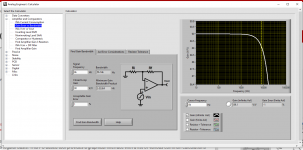
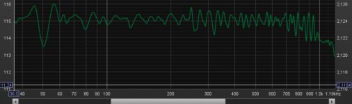
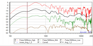
For most of the loudspeaker measurements and filters post processing, I use Acourate. All measurements were performed at a space of some 70cm-80cm, the distance where I sit while spending time at the PC. A «high» measurement was made at my head height (red graph), a «low» one at the heigth of the desktop plane (brown graph), and an «intermediate» one (green graph) at an elevation in between «low» and «high».
Native.png
Low (Brown) at more or less zero elevation from the desktop plane and also at the height of the loutspeakers show a +-5dB behavior from 150Hz … 15kHz, which is quite remarkable for such a simple and crude setup. A single, decent +4dB … +5dB peaking filter centered at about 4.5kHz … 5kHz would provide an even better result.
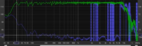
Intermediate (Green) and High (Red) are roughly 15° and 30° out of the direct radiating axis of the BUF Indoo. The frequency response is much more uneven than inline which call for a more elaborate equalization. For practical reasons, I had Acourate then compute an averaged and smoothed curve (black) out of both responses.
DSP by Camilladsp:
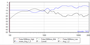
Along with CamillaDSPs IIR filters, this black average could be reasonably corrected by three peaking filters and a single shelving filter: A fist, broad, low-Q peaking filter, attenuating -4dB at 500Hz, a second peaking filter boosting +3dB at 4kHz, and a third peaking filter attenuating -3.5dB at 8.5kHz. Finally a shelving filter of some 8dB centered at 2kHz will bring the response into a reasonably flat state. IIR filters declarations are very handy if you want to experiment with different sampling rates. One filter declaration fits all use cases, then.
Instead, I decided to generate and apply a FIR filter (blue), which roughly corresponds to the inversion of the averaged black response. Keep in mind that you might set the max. level of such a corrective filter intended for a realtime-convolution to max. 0dB. It is even wiser to set such a filter to a max. of -2dB … -3dB to be shure to avoid intersample clipping.
Inverse.png
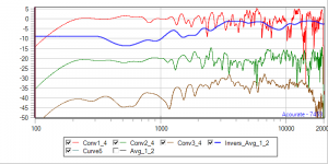
A test convolution of this filter on the upper (red) and mid (green) response shows neat results for both cases. As expected, the (initially more or less linear) low response (brown) now suffers and shows more or less the characteristic of the corrective, inverse filter. Nota bene: If you mess around with FIR filters and different sampling rates, then you will need one filter (or one filterset in case of a multiway x-over design) per each sampling frequency you might use.
Convolution.png
DSP is really nice. Besides of the correction in the frequency domain as explained above, it is easily possible to implement also a moderate interchannel crosstalk compensation. In the pipeline section of the CamillaDSP configuration file, you have to first split the stereo channels into four subchannels by a mixer, then apply the cancelation, and then merge the four subchannels back into the two stereo signals, now including the cancelling information in each channel. Using some trigonimety, at a listening distance of 80cm with an interaural distance of 27cm and a loudspeaker stereo basis of tiny 7cm the interchannel difference of the pathways results to 1.16cm, which at a speed of sound of 343m/s results in a teeny weeny delay of 0.034ms to apply for the cancelling signal.
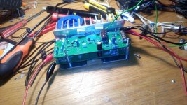
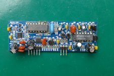
My desktop computer runs as a Windows 10 system. I configured CamillaDSP to use the onbaord Realtec S/PDIF soundcard/soundchip section as the shared capture device in loopback mode. This runs nice up to 192kHz. CamillaDSP outputs to a dedicated, internal PCI RME HDSP 9632 Soundcard in shared mode also. There is even no need for an amplifier. The phones output of the RME soundcard is just loud enough.
Outlook:
Thats it. It was a fun and somehow hilariously simple project. And as the BUF Indoo even has a somehow ridiculous optical characteristic, I consequently will leave the whole box as is: As a kind of weird cardboard-glue-and-argile-sphere agglomerate. No black piano stain. No. Not really … Such a piano-stained version might be the case for a next iteration. Then, maybe with some decent and optional sidewalls from the side of the monitor to the desktop also, forming some kind of four-walled-horn. Maybe. And maybe not.
Appendix:
The CamillaDSP config.yml (subject to change ...)
Code:
---
devices:
  samplerate: 192000
  chunksize: 4096
  silence_threshold: -90
  silence_timeout: 3.0
  target_level: 2048
  queuelimit: 4
  adjust_period: 10
  enable_rate_adjust: true
  enable_resampling: true
  resampler_type: AccurateAsync
  capture_samplerate: 192000
  stop_on_rate_change: true
  rate_measure_interval: 1.0

  capture:
    type: Wasapi
    channels: 2
    device: "Digital Audio (S/PDIF) (High Definition Audio Device)"
    format: FLOAT32LE
    exclusive: false
    loopback: true

  playback:
    type: Wasapi
    channels: 2
    device: "Analog (1+2) (RME HDSP 9632)"
    format: FLOAT32LE
    exclusive: false

filters:

  # xtalk_compensation filters (delay, gain and inversion)

  flt_delay_xc:
    type: Delay
    parameters:
      delay: 0.034  # D=80cm, LS_separation=7cm, IAD=27cm
      unit: ms
      subsample: true

  flt_invNgain_xc:
    type: Gain
    parameters:
      gain: -1.5  # No full compensation
      inverted: true

  flt_lowshelf_xc:
    type: Biquad
    parameters:
      type: Lowshelf
      freq: 1000
      slope: 2
      gain: -10

  # Frequency range linearizing filters

  flt_conv_frng:
    type: Conv
    parameters:
      type: Wav
      filename: inverse_hm.wav
      channel: 0

  flt_gain_frng:
    type: Gain
    parameters:
      gain: 12  # Compensation for the convolution process gain loss - this will cause some clipping !!!
      inverted: false

  # other DSP filters

  flt_gain:
    type: Gain
    parameters:
      gain: 0

  flt_volume:
    type: Volume
    parameters:
      ramp_time: 200

mixers:
  mxr_xc_merge:
    channels:
      in: 4
      out: 2
    mapping:
      # 0 ipsi
      - dest: 0
        sources:
          - channel: 0
            gain: 0
            inverted: false
      # 1 ipsi
      - dest: 1
        sources:
          - channel: 1
            gain: 0
            inverted: false
      # 0 <- 1x
      - dest: 0
        sources:
          - channel: 2
            gain: 0
            inverted: false
      # 1 <- 0x
      - dest: 1
        sources:
          - channel: 3
            gain: 0
            inverted: false

  mxr_xc_split:
    channels:
      in: 2
      out: 4
    mapping:
      # 0 ipsi (0 -> 0)
      - dest: 0
        sources:
          - channel: 0
            gain: 0
            inverted: false
      # 1 ipsi (1 -> 1)
      - dest: 1
        sources:
          - channel: 1
            gain: 0
            inverted: false
      # 0x (to be processed as the part of ch 0 signal in order to cancel the crosstalk from ch 0 to ch 1)
      - dest: 2
        sources:
          - channel: 0
            gain: 0
            inverted: false
      # 1x (to be processed as the part of ch 1 signal in order to cancel the crosstalk from ch 0 to ch 1)
      - dest: 3
        sources:
          - channel: 1
            gain: 0
            inverted: false

pipeline:

  - type: Mixer
    name: mxr_xc_split

  - type: Filter
    channel: 2
    names:
     - flt_delay_xc     # delay for the cancellation signal to match the longer x-path travel time
     - flt_lowshelf_xc  # we do not want to dim the lower frequency range too much
     - flt_invNgain_xc  # gain filter comes along with the signal inversion for the cancellation effect

  - type: Filter
    channel: 3
    names:
     - flt_delay_xc
     - flt_lowshelf_xc
     - flt_invNgain_xc

  - type: Mixer
    name: mxr_xc_merge

  - type: Filter
    channel: 0
    names:
     - flt_conv_frng
     - flt_gain_frng
     - flt_gain
     - flt_volume

  - type: Filter
    channel: 1
    names:
     - flt_conv_frng
     - flt_gain_frng
     - flt_gain
     - flt_volume


 Hi All,