RF 50Mhz capable power tubes (and low voltage)?

Does anyone know of any lowish power tubes capable of 50Mhz? Say in the 200-600V range? I'm asking as a last chance before I settle on a mosfet output stage for any power use. The tube itself would only be used at 24Mhz but more tubes are available into the 50Mhz band.

I'm aware that switching at this rate has been the reason for high voltages. Plus to be honest I would not be comfortable attempting a 1kV+ device, even if it was in a fully closed shielded case with separate compartments for the kV components.

GU-81M is 1.2KV
6HV5 is 5KV

GU-46 (60MHz) could be possible - more modest B+.

I've read the GU-81M threads for the audio amps made using these. Given the B+ values these would need a large voltage swing depending on the mu which then means needing a drivers stage capable of 50Mhz - so my thinking here is that there must be a driver tube that fits the bill?


e88cc is an option for line output (this is used in MarcelG's DAC) However I was wondering if there's an option to make a tube power section using the same.

Just research for my next tube amp at this stage.

Transformer with 2 secondaries connected to 2 rectifiers powering different grounding devices

Hello. I have an old transformer with 2 separate secondary windings - 32V-0V and 14V-0V. I would like to connect to both of these windings 2 separate ractifiers, of which first would power device with positive ground (amplifier) and second would power device with negative ground (tape recorder).

The thing is that I want to connect audio inputs and outputs of recorder and amplifier. So I want to connect positive ground of amp with negative ground of magnetophone.

Can I use for this 2 separate secondary windings of my transformer, or I have to use separate transformers for both devices?

FS: DIR9001 to CS8412 converter board

This is a newly completed project for a DIR9001 to be used in CS8412 socket digital receiver DACs. The board is proven working in my D1 Ver2 clone DAC and will also be working in other DAC which accept 16 or 24 bit format as stated in DIR9001 data sheet. The only thing I want to highlight is the low 50ps jitter of DIR9001 compare to old receier 8414/8412 with >200ps jitter.

Price is US$5 with below content:
1. Two 14 pins strip.
2. 4 0.1uF smd chip cap
3. 2 10uF smd chip cap
4. 1 22uF smd chip cap
5. Some 2.5mm pins
6. One smd bead

Buyer pay shipping $1 for normal airmail and $3 for registered airmail. Paypal charge is 4%.

The rest of parts can be ordered from Farnell. Interersted please PM me.

Attachments

  • 9001_topm.jpg
    9001_topm.jpg
    62.7 KB · Views: 2,796

Citation 16A by Harman Kardon

Just acquired this amazing, and by many highly praised, Harman Kardon amplifier. I immediately liked the sound over my Yamaha A-780 ( okay, they are two quite different animals ) and even my wife said "Hey, I like this sound". It came with some issues which seems to be common to all of them after so many years, and I am interested if someone has done some kind of upgrade on this amplifier , and what was the experience, what is worth to do? One thing, resistors on emitters of output transistors are 0.5 Ohms, 5 Watts and 10% ?? I am thinking to replace them with 1% resistors ( 5 W, of course). Would it be good move, or can tighter tolerance cause problems? Thanks for any opinion.

Fostex FE108e∑ - still a thing? Maybe FAST / WAW

It seems these drivers are still being made and sold, they have been around a looong time. Heck, I remember Dave D said they were his favourite back in 2005….

But are they still a thing? Nobody seems to post on these drivers much anymore. Are they about to go extinct?

Would they not make good options for a FAST (mid-tweet in a two-way) given their 90dB sensitivity ?

Crossover acting weird, please help

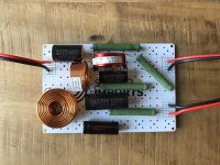
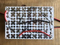
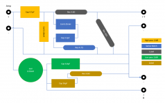
I'm in the process of building a small budget speaker using Dayton drivers, the TCP115-4 and ND25FA-4. I measured my drivers' raw responses and modelled my crossover using these measurements. I built the crossovers, but there seems so be something wrong.

The bass driver is almost completely silent. At first I thought it didn't do anything. The tweeter does make sound, but not very loud, and the TPA3116 amp switches of momentarily if I crank the volume up to about halfway (seems some built in protection).

Things I already checked:
  • Checked my circuit layout at least 5 times
  • Checked with another amp (TDA7498E), same result
  • Disconnected the zobel network, no effect
  • Disconnected the notch network, no effect

I don't understand what's going on here. In the simulation software everything seems fine (though the impedance is quite low). Could anyone review my crossover and check it for errors?

Attachments

  • XO_topside.jpg
    XO_topside.jpg
    325.8 KB · Views: 243
  • XO_backside.jpg
    XO_backside.jpg
    252 KB · Views: 225
  • XO_Visio.PNG
    XO_Visio.PNG
    17.9 KB · Views: 220
  • Koala (xsim).dxo
    Koala (xsim).dxo
    6.6 MB · Views: 110

Rockford Fosgate symmetry epx2

I have a Rockford summertry epx2 .

The issue I’m having with with unit is output level and the 28 band eq card doesn’t function properly .

First issue . The manual setting for the pre output it’s is 128 I have to set the unit at 165 to get any kind of decent output out of it .

Next issue is the indicators on the 28 band eq card don’t work correctly . Right channel the lights do nothing at all . The left channel only the red led flashes like I’m clipping the signal .

anyone have any ideas or are familiar with these units ?

Rockford doesn’t work on these and doesn’t know anyone that repairs them anymore

Drilling thru 10mm Alu and broke my bits. Help?

Working with the 10mm aluminum front plates from the DIY chassis. I'm trying to drill holes for a push power button, led, and attenuator.

I typically measure and start with a center punch, and then use stepped bits to open up a hole. Here's an example of a 1/2" hole I made in a panel today, to prove I'm not a complete doofus.

PXL_20211219_032000823.jpg


However, with the 10mm front panel, my bits are immediately becoming dull and sometimes breaking off. I was finally able to open the hole up to 1/8", but I can't get my stepped bit to catch in the hole. Right now I'm left with what feels like an ugly and expensive mistake, as well as a number of trashed bits.

PXL_20211219_030406273.jpg


I'm stuck and feeling a little discouraged. Surely there must be a way to drill through these front panels?

Should I be using a drill press and forstner bits? What am I missing here?

Subwoofer Economy?

I'm looking at building a nice and powerful subwoofer to reinforce the low bass produced by my 5-channel bass reflex rendition of the German MTM configuration by Zalytron (using Axon 6S3 woofers and T1S tweeters).

Now, I don't have a whole lot of cash, so I don't really want to spend > $150 USD on the subwoofer. Leaving me with two options. Purchase a genuine subwoofer like the ACI SV12, or purchase a set of cheaper large woofers. Apex Jr is offering a surplus 12" woofer for $50. Specs:

http://www.apexjr.com/images/W12P1.jpg

Now, I am wondering if it is more likely for me to find something along the lines of the SV12 better or worse than several of these W12P's. I am not so worried about the specific drivers, but rather what I am most likely to find works better: woofers not really designed for the job of a subwoofer but several or a singler subwoofer.

My specific goal here is powerful, but controlled bass.. I might look at a bass reflex alignment because of the good results I have had with them in the past.

Edit: Graphs for wrong driver were included.


[Edited by Ignite on 09-18-2001 at 01:57 AM]

Mechanical issue with my Acoustat Spectra 22

I could use some help with a non-urgent problem with one of my Spectra 22... Someone (me) snagged the 15VAC bias supply cord and apparently broke/detached the female 3.5mm socket internal to the MK-2123 interface box. Before I dismantle the speaker and dig into the MK-2123 it would helpful to know what sort of socket is used! Does anyone know how that socket is attached to the PCB?

The bias supply is fine and the speaker plays fine as-is, which is why I describe the situation as non-urgent. If someone were to unplug the bias supply, however, it could become a major problem when trying to plug it back in!

SEAS FA22RCZ build

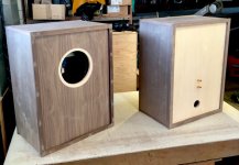
I have been enjoying these for the last few weeks now and I'm very impressed! I used the plans Scottmoose released for a large vented cabinet for the FA22RCZ. I used walnut ply for the sides and Baltic birch for the front and rear baffles (front has walnut veneer). The bracing was not in the plans but was recommended. I did use a 1.5mH inductor in series with a 15 Ohm resistor (as per the Seas application note) to tame the HF but with this small change I find these hard to beat! They are one my favorite builds to date! Thanks to the exceptional cabinet design and Scott for posting it!

Attachments

  • IMG_3212.JPG
    IMG_3212.JPG
    110.7 KB · Views: 1,532
  • IMG_3225.jpg
    IMG_3225.jpg
    74.9 KB · Views: 1,637
  • IMG_3236.JPG
    IMG_3236.JPG
    94.2 KB · Views: 1,577
  • IMG_3369.jpg
    IMG_3369.jpg
    91.3 KB · Views: 1,857

Any Suggestions For a Clean Amp Design?

I'm looking to build an amp with a decent amount of clean headroom to play both at home at low volumes and also with a few friends (drums and bass). I would like to have a decently clean amp for testing out pedals, and I want to have enough headroom to stay relatively clean while playing with drums. Anyone have any good suggestions for what I should be looking for? I was initially thinking something with four 6v6's as the output stage. I have a couple of These that I've had for years, so I was thinking about doing a 1x12 setup with one of those. They're fairly efficient speakers, so I was hoping I could get away with a lowish power amp and still get a decent amount of volume before breaking up. Does this seem reasonable? If so, can anyone recommend a clean amp design with good tone that would fit the bill?
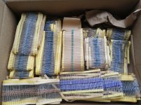
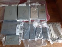
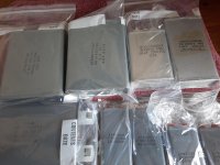
Resistors -- 4 medium flat rate boxes -- organized listing this time --

Please no PM's please :Ohno:
Reply in this thread.
Local pick-up, is a great option, 03063, NH.

$55 shipped (USA) per box or best offer.

When making an offer:

1) Mention which box you want, this is a number.
2) The amount your are offering (shipped), this is also a number.
3) Your zip code, yep, you guessed it, also a number.

Payment is via Paypal, goods and services or Personal Payment.
You can pay personal payment ("no fees", "not goods and services") and get it cheaper, but I need an extra payment of $1, so I have your shipping address and can print a label.

BOX 1, weighs ~7.5 lbs:

Attachments

  • IMG_20191022_112520.jpg
    IMG_20191022_112520.jpg
    1 MB · Views: 1,590

F6

Hey everyone,
welcome back to the obsession!
Can’t believe how much I missed this site.
Anyway, I just completed an F6 amplifier and have 15 hours on it now. I have the bias set at 560 mv on both channels. The bias is stable and I’ve only adjusted it from 510 to 560 and only after amplifier is fully warmed up. I’ve been monitoring heatsink temperatures with an IR thermometer and see 51c at pin 2 on mosfet. The temperature varies on each mosfet though I’m not sure how much that matters. I’m monitoring highest temperature before bias adjustment. All that said I haven’t noticed much change in sound quality yet. I suppose patience is in order? I’ve been using my Onkyo CDP C7030 as a source and for the first time last night I switched the source to my Mac mini through my HRT music streamer. It’s an asynchronous usb dac that I’ve had for several years but sadly is my only option for conversion duties when using the mini. The difference in SQ was quite noticeable. So apparently the dac in my cdp is somewhat better than my HRT. My speakers are diy full range using MarkAudio 12p. I’m hoping for suggestions, should I increase bias to 600 mv or just let it run in longer? I do have a diy dac planned but given how long it took to get my f6 going it’s going to be awhile before that’s ready. Suggestions, please
Sure is great to have the site back 😃
Regards

Attachments

  • 9667A6C7-2F5D-417B-96B0-FC2076935243.jpeg
    9667A6C7-2F5D-417B-96B0-FC2076935243.jpeg
    259.1 KB · Views: 198

Muses 72323 Input Selector, Buffer and Volume Control

Dear All,

I have those boards available. This thread is for technical discussion. The boards have an input selector (4 inputs), a DCB1 buffer and a Muses 72323 based volume control. Power supplies (+15V, -15V, 5V) are also included on board with low-noise regulators. The circuit can be controlled with an Arduino.
This is a byproduct of my F5X project, so in my final build, the volume control is followed by a gain stage. The buffer can be left out, if you do not need it.
I am not aware of any other development board based on Muses 72323.

Merry Christmas,

Davide

Attachments

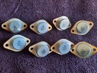
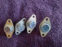
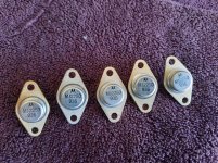
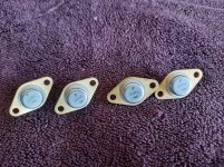
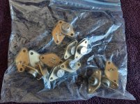
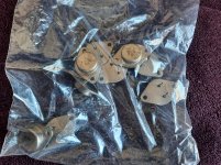
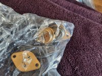
Vintage audio power output transistor transistors I think -- NH USA --

Best offer

Attachments

  • 20210520_143732.jpg
    20210520_143732.jpg
    594.9 KB · Views: 320
  • 20210520_144045.jpg
    20210520_144045.jpg
    1.1 MB · Views: 370
  • 20210520_144137.jpg
    20210520_144137.jpg
    1 MB · Views: 334
  • 20210520_144317.jpg
    20210520_144317.jpg
    1.1 MB · Views: 323
  • 20210520_144344.jpg
    20210520_144344.jpg
    1.1 MB · Views: 293
  • 20210520_144450.jpg
    20210520_144450.jpg
    1 MB · Views: 220
  • 20210520_144525.jpg
    20210520_144525.jpg
    1 MB · Views: 246
  • 20210520_144551.jpg
    20210520_144551.jpg
    1 MB · Views: 221
  • 20210520_144610.jpg
    20210520_144610.jpg
    1 MB · Views: 172
  • 20210520_144628.jpg
    20210520_144628.jpg
    1 MB · Views: 229

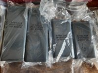
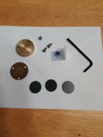
Audio Silente Bronze Bearing end cap, 3 thrust pads and G5 6mm Ceramic BB

For Thorens TD-124. SOLD SOLD SOLD

Selling my very lightly used Audio Silente Bronze Bearing end cap with gasket. 2 PVC (AS supplied) thrust pads one lightly used so other side fine and the original Thorens Nylatron thrust pad one side used a lot the other only a few hours. Gasket Plus a Audio silente 6MM Grade 5 ceramic ball bearing.

An excellent soultion to upgrade your Thorens stock end cap. I am a bit anal and bit the bullet for the Woodsong endcap, thus I no longer need this.

Simone sell this kit on ebay for $55 plus $24 shipping and that does not include the ceramic BB. I am asking $40 usd plus shipping (priority mail small flat rate box) if using paypal non-family and friends please add 3%.

Attachments

  • AS Bronze Bearing endcap.jpg
    AS Bronze Bearing endcap.jpg
    352.5 KB · Views: 191

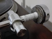
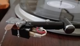
Tone arm Micro Seiki MA 707 and Cartridge DL 103, happy end !

I had a happy ending odyssey with the Denon DL103 cartridge and its pairing with the Micro Seiki MA 707 arm. 😊
As many of you already know, the fame of this cartridge is great, but to extract its full potential you need a heavy arm, because it was designed for radio stations in Japan at the time (1962!) And they all had the classics. turntables of the time, robust, heavy and with lossy tonearms - compared to arms that were later manufactured for high compliance MM's cartridges - approximately 70/80 decades onwards -, typical Shure V-15 and others .
So after thoroughly reading the following links and debating on the turntable forum without much luck, I decided to go ahead and not settle for the extra mass load of the accessories provided by MS for the MA707. These are, a "rider" and a screw behind the pivot point. The sound was good, but "something else was missing".
I had already tried to add extra weight to the head (6 grams) but that forced me to move the rider almost to the top of the pivot point and bring the adjustment weight - for balanced - to the opposite end, one more full turn and he would fall. !
And the result was not good, there were no improvements with respect to the conventional setting recommended by MS, and also there was a tendency to couple that clearly indicated that the arm was going into resonance at high volumes. (Now that inconvenience is overcome).
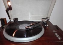
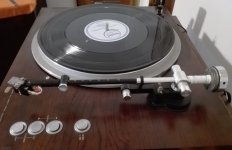
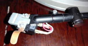
So I went to my workshop and looked for several washers, drilled them to 12 mm in diameter, wrapped the back of the pivot point in Teflon to avoid damaging it and once the balance was achieved, a few extra turns of Teflon locked the washers in its place.
As you can see in the attached photos, the rider is closest to the head (the idea was to maximize the mass of the arm at its two ends, that is, to increase the grams of the accessories provided by MS) the head shell now has a Extra lead of 6 grams, (the original is plastic and very light, suitable for high compliance cartridges but not for this Denon DL103 that has a suspension similar to the wheels of a train). The result of all this is fantastic, now I do feel that I entered the "famous Denon DL103 Club", so I will not do any more experiments, the increase in the total effective mass was a great goal.
This now sings for real! The soundstage has opened, the dynamic range has increased, the bass is deep and fast. And I still need to try raising the load of the phono preamplifier from 470 to 1000 Ohms to see if the treble rises something, in the leaflet
that came with the cartridge it indicates that it was tested with 1 Kohms, an apparent Denon contradiction, because in the Attached brochure describe as recommended load 100 Ohms.
While I don't think it makes much of a difference, I'll give it a try, that's easy, just run two Dip's.
It is clear to me then with practice that the "classic problem" of this cartridge is absolutely true, it is not suitable for modern conventional arms. (Lightweight and low effective mass)
I could not imagine that a manufacturer like Micro Seiki would provide accessories for MC - extra weights - that did not get to extract everything possible from the DL103. It is a cartridge with 40 Ohms of impedance, and there are not many with that value, they are usually 10 Ohms. Also "special" is its compliance measurement of 5, taken at 100 Hertz instead of 10 Hz, VE has a resonance calculator for arms and cartridges, I used it a lot of times trying to find the "holy grail" there, but for this cartridge, it does not give a realistic result, because it is developed for cartridges that measure their compliance at 10 HZ.
The idea is to buy new washers, - they look awful, yes - glue them together, and put Teflon back more neatly, I also forgot to weigh the washers, in the next "makeup" operation, I will do it and inform you . 😉

Attachments

  • MA707 y DL103 Vista final ajustes.jpg
    MA707 y DL103 Vista final ajustes.jpg
    101.8 KB · Views: 377
  • IMG_20211222_171330.jpg
    IMG_20211222_171330.jpg
    242.2 KB · Views: 324
  • IMG_20211222_171356.jpg
    IMG_20211222_171356.jpg
    207.3 KB · Views: 335
  • IMG_20211222_171409.jpg
    IMG_20211222_171409.jpg
    141.7 KB · Views: 341
  • IMG_20211222_171424.jpg
    IMG_20211222_171424.jpg
    201.7 KB · Views: 400

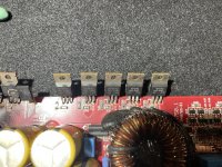
Kicker 06ZX750.1 SMD gate resistors?

Trying to find these smd resistors to buy, power supply side mosfets melted down on this amp due to stray wire (all gate resistors on PS side all measure 10Ohm/spec) and the gate resistors on the output side are reading all wonky but mosfets are all good, SMD104 are reading between 33kOhm-100kOhm (spec value is 100kOhm which only a very few are reading as that) and 1x SMD100 isn’t reading at all, so I’m thinking I need to replace the ones not reading right while I’m replacing power supply mosfets with new IRF3205. Any help with part numbers on the DigiKey.com site would be great, they look to measure 3mmx1mm each. New to amp repair so I apologize for my newbness, I posted about this amp in Amp Power Supply page. Also should the resistors measure their value and that’s that or can anything effect their reading? I was reading, if I remember correctly, that they should measure their spec value within maybe a 5% tolerance and if they don’t they are bad. Got my spec values from resistor calculator online via markings on the SMD. Any help on this would be great, ty!

Attachments

  • BBD966B0-C674-4A4D-86B0-D6FC5A7EF600.jpeg
    BBD966B0-C674-4A4D-86B0-D6FC5A7EF600.jpeg
    845.9 KB · Views: 149
  • CF1D8EF8-AC4F-4F2B-A70A-13D2EA51D734.jpeg
    CF1D8EF8-AC4F-4F2B-A70A-13D2EA51D734.jpeg
    655.9 KB · Views: 120

RME fireface 800. Need help on finding a component.

Hi,

I recently bought a defected Fireface. The problem seems to be on the firewire input/output. The module doesn't speak to my mac.

I opened it up and could see a missing, and probably burned component. The label says VD1202. Anyone with schematic or similar fireface who knows?

Attachments

  • 12544895_10153655303492107_120948947_o.jpg
    12544895_10153655303492107_120948947_o.jpg
    187.8 KB · Views: 274

Old V-FET. Sony, Sanyo

I was doing some Spice analysis on my old Hafler/modified amp, looking at Ron Elliot's , and several others. I was thinking of the history of the Hafler, from the original work Erno did for Hitachi, to the DIY articles to the Hafler. Along there came the Sony integrated, which I had and remember fondly for the sound, but high noise level, and a Sanyo Plus P55 which also sounded great except for the heat pipe gurgling.

I have not found schematics for either of these. I would be curious if they share anything with E.B's designs.

I did find a hint why a driver stage in a MOSFET amp. Input capacitance of the outputs. For a low power, like the DH120, probably not needed, but if doubling or more the outputs, then it does become an issue. More outputs have advantages, but idle current goes up. I can see the attraction of current dumping so class B.

Finishing a old abandoned SE amp. Some modefication questions etc.

I bought a abandoned project that was 80% complete.
Some capacitors was missing and the ccs and mosfet circuit was not finished .

I found some of the obsolete parts but not the Mosfets. But i read on this forum that you could use 2 different types.
2SK3564 or FDPF5N60.
I bought both. So witch one should i use?

Second question:
The power transformer i got are from a chinese 300b SE amp. It was wired with a separate heater winding for each 300b tube. So im thinking on cutting the traces on the SE pcb to one of the tubes and make a secondary rectifing circuit on a small protoboard for the other tube. So what parts do i need to get that up and Running? And where to cut? 🙂. I have 2 x PQ5EV5 🙂

Microphone circuit for Zoom H4 capsule

Hi everyone,

I have a dead Zoom H4 and I want (for the exercice) to transform its two electret microphones into two distinct standard phantom powered mics.

What I've done so far:

I tested the circuit and "yes" it kind of works, but I have to push my preamp to its limits and thus have a lot of noise. I'm using a breadboard so part of the noise eventually comes from that.

How can I improve the mic gain ? (I have no specs on this particular capsule)
Maybe adjusting values for the two 2k2 (or 5k6) resistors ?

Thanks a lot for any advice !

For sale - Najda v1.3 DSP with control board

SOLD - Najda v1.3 DSP with control board

**** SOLD ***

I am selling a brand new Najda v1.3 DSP with control board and PSU.

The packet has never been opened. Bought it in november 2015.

The price is 270€ and shipping including insurance is about 20€

I live in Denmark near Copenhagen but I can mail it to you if you live in the EU.

WAF-Audio

Car sound deadening material for house wall vibrations?

Hi all,
is anyone using car-sound deadening materials in home construction to reduce vibrations?
I am talking about stuff like "Dynamat", "Noico" and many others, self adhesive material.

I have an interior basement wall that vibrates a lot due to HT subwoofer.
The wall is build of 1/8" panelling (the 70's style old house) on 6" studs.
It is a sound pressure created vibration, not direct transfer from the sub.

I have access to the wall from both sides and can get to the panels from the inside. I'd prefer not to change the panelling to drywall, hence my question about sound/vibration deadening materials.

Thanks in advance!

🎄Rotel bridge rectifier replacement 🎄

Hi all, and a Merry Christmas🎄🎄

I'm looking to replace the bridge rectifier on a Rotel 920ax amp. Currently it's a pbp206, which is no longer made, and as I understand it needs to be improved upon in this amp, as Rotel's have a habit of eating their rectifier.
What would be a suitable option that can be relied upon in the long term.
(Have attached the service manual)
Thank you all in advance 👍
Seasons best wishes to all 🎄🎄🎄

Attachments

F5 & acoustic bass, where is it?

I built an ACA and was quite blown away, then did an F5.

The F5 isn't housed in a chassis yet, but wires are fairly well separated.
Its got maybe 15hrs on it. It seems to be missing something in the upper bass, the acoustic bass in Tears in Heaven by Clapton (live) has almost disappeared, its very faint.
The ACA presents the same song bewdifully!
Checked all phasing which was fine, yet the lower bass registers are also fine. I noticed the upper bass missing in quite a few other CD's but never really nailed exactly what was missing until I played Tears in Heaven.

F5 bias is set at 0.59vDC, DC offset 10~15mV.
I have P1 mounted, set mid range (30 turn pots) so set at 15 turns
Heatsinks are static at 39degC
Rails are +/- 22.8vDC

It's using the following;
Antek 5218
Monolithic 35A Rectifiers
16 gauge wire for DC power
Twisted CAT5 for inputs
16 gauge output wire
120,000uF Caps total (+ and -)

When I changed the ACA v1.8 out for the F5, I changed nothing else.. just the amps.

Attachments

  • original transfo secondary phase left to top right corner of rectifier - bass didnt dig deep eno.jpg
    original transfo secondary phase left to top right corner of rectifier - bass didnt dig deep eno.jpg
    741.3 KB · Views: 608

Under Investigation Select and Quote on mobile

The new feature that allows one to select text in a post and then be used as a quote. It works well and is very handy on desktop, but seems quirky on mobile.
I've gotten it to work only once. Every other time I've tried it takes me to the reply window, but the quote is not there. Is anyone else having this problem? Or am I doing it wrong?

TDA7293 project

Good evening gents,
Apologies, posted initially in the wrong place - will get the hang of things.
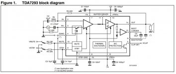
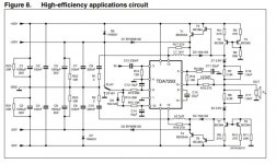
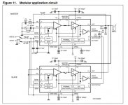
I'm laid up, no driving licence for 'dicky ticker' reasons' from October so I'm crawling up the walls. I have a weeks holiday at Christmas so I thought I'd get on with an audio project. I have a Rega record deck gathering dust on top of the wardrobe I thought I'd have a go at building an amp, not from discrete components I hasten to add. I've spotted the TDA7293 which seems ideal as a basis for this and studied the data sheet which has a couple of example circuits one of which is described as a TDA7293 block diagram. This diagram appears to relate to a PCB layout and is quite straightforward ie few components.. Is this a working circuit, I thought I'd knock it up over Christmas well at least the PCB. There are a couple of other circuits (modular and high efficiency) which are also on my radar although the component count of one is far higher. What are peoples thoughts on the circuit I should go for. Thanks in advance.

Attachments

  • Block crc.jpg
    Block crc.jpg
    90.9 KB · Views: 171
  • HiEff.jpg
    HiEff.jpg
    67.4 KB · Views: 192
  • Modular app.jpg
    Modular app.jpg
    77.4 KB · Views: 179

IanCanada's RPi4 + DAC + Clock + I/O + Power supply

Hi all,

I have been trying to understand all of IanCanada's offerings on Github.
GitHub - iancanada/DocumentDownload: Download documents of Ian's products

My idea is to use his board to build an RPi4 based Streamer/Player/DAC.

I would like the DAC to communicate to the RPi via I2S and have additional inputs for my laptop (USB), CD Player (SPDIF COax), Game Machine (TosLink), and mobile device (BT). I tried making a list of boards I would need but got lost.

I could not find any USB or BT input board nor how to connect the RPI to the DAC via I2S.

I do not need SPDIF outputs, I only need RCA and XLR, at this stage but if the space permits I don't see why I should leave them out.

I also don't want to get into the complications of a battery power supply because I don't know what it entails (Capacitor Conditioners, etc.).

I tried to make a list (see below) but would rather if a complete kit was available or maybe if someone help me determine which boards I would need.


BridgePi Adapter USB Interface to GPIO
DocumentDownload/BridgePiUsersManual.pdf at master * iancanada/DocumentDownload * GitHub

Isolator Pi II - I2S, DSD, DOP Isolator
DocumentDownload/IsolatorPi at master * iancanada/DocumentDownload * GitHub

FIFOPI Q3 ULTIMATE FIFO Reclocker
DocumentDownload/FifoPi at master * iancanada/DocumentDownload * GitHub

ShieldPi
DocumentDownload/Adapters/ShieldPi at master * iancanada/DocumentDownload * GitHub

Dual Mono ES9038Q2M DAC HAT
https://github.com/iancanada/DocumentDownload/tree/master/RPiDacHAT/ES9038Q2MDualMonoDacHAT

Transformer I/V (SE, Bal, Headphone)
https://github.com/iancanada/DocumentDownload/tree/master/RPiDacHAT/IVboards/LL1544aTranformerIV

I2S to HDMI Transmitter and Receiver
https://github.com/iancanada/DocumentDownload/tree/master/HDMIpi

Receiver Pi for TosLink and Coaxial Input
https://github.com/iancanada/DocumentDownload/tree/master/ReceiverPi
OR
SPDIF Inferface Board
https://github.com/iancanada/Docume...II series/SPDIFboard/SPDIF_InterfaceBoard.pdf

TransportPi for SPDIF, BNC and Optical output
https://github.com/iancanada/DocumentDownload/blob/master/TransportPi/TransportPiUsersManual.pdf

ESS controller + extension kit
https://github.com/iancanada/DocumentDownload/tree/master/ESScontroller

Dual Linear Power supply
https://github.com/iancanada/DocumentDownload/tree/master/LinearPi

Thanks

Bandpass passive radiator - how to model

Hello everyone! I'm trying to design a compact home subwoofer using a pair of Hertz HS300 car subwoofers. I'm using them in a push-pull, 4th order bandpass configuration. They model pretty well on WinISD and BassBox in a 15lt(sealed chamber)+5lt(vented) bandpass enclosure tuned at 60Hz. I get a nice flat curve with low group delay with, even if I lose 9dB of efficiency it stays manageable (should be of around 82dB/W after being put in this bandpass box).
But doing so I encounter the usual issue with small displacement bass reflex subwoofers: the port is too long to fit in the box, even if I fold it. Reducing the diameter by a lot seems to help (I still need to fold the port) but because of the high Xmax and diameter of the subwoofers the vent air velocity is too high. This will lead to power compression issues and potentially port chuffing.
This issue is usually solved by replacing the traditional cylindrical or slotted port in favour of a more manageable passive radiator. However, I have no clue about how to deal with this particular situazion in which the bandpass enclosure and a PR are used in conjunction. How do I model the enclosure, and how do I find the correct mass to add to a PR of my choice?
I've been able to find some info on the internet about this type of use for the PR but no design tips.
Has anyone ever dealt with this problem?
Thanks
Piergiorgio

GERMANIUM Single ended Class A Headphone Amp.

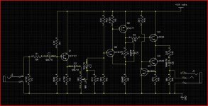
Presented here is a small Class A single ended output headphone amp, unusual because it uses germanium devices.
Why germanium ? Well I have few of these wonderful old devices, and a heaphone amp seemed an ideal little project. There's another reason too... I am working on a new amp (eventually) and headphones are a great way of evaluating circuitry... so I wanted something good.
To anyone not used to seeing and working with germanium, well it probably looks a bit "all upside down" using a positive earth.

Let me say first off that this isn't by any means a "finished" design... it's still a work in progress.
It's 15 years or more since I did any serious headphone listening and my old Sony MDRV-7's were used in the design of this. I must look into more modern replacements.

The low supply voltage probably stands out, 6.8 volts... is it enough for decent output ? Well it appears so for me, and it drives the Sony's to way higher than what would be considered "safe" levels, although the efficiency of these old cans is high I think, compared to some. The supply can always be altered though, and in actual fact isn't the only limiting factor here. That comes from the constant current source Q4 and 5. The 3.3 ohm gives around 50ma in the outputs and at 6.8 volts they run at a reasonable temperature. This is germanium after all. Even swapping this resistor out to 43 ohms still allows decent levels before soft asymetrical clipping occurs.
One thing this design is if nothing else is tweakable... so non of these issues are a major stumbling block. As I say, it's not a final design yet.
The ACY21 is used as a buffer to provide a known input impedance, and to enable the volume control to be unaffected by the signal source... probably an unnecessary extra stage you might think, however listening tests reveal no problems including it... it may even help "soften" the presentation... in the nicest possible way of course. I tried direct onto the volume control, and then with the ACY21 and "think" the extra stage possibly adds a little indefinable something. Q2 and Q6 form a classic two stage amplifier. The supply (no decoupling shown) comes from a 7906 regulator with a 1n4148 lifting the ground leg to provide around 6.8 volts.

So how does it all sound... well I think it's pretty good, but then I would say that wouldn't I. It's certainly more "engaging" to listen to than a normal opamp offering... in fact it's pretty stunning. There is a razor sharp clarity, yet with absolutely no hint of harshness or stridency. I suspect the "not so low" output impedance is actually a match made in heaven for the phones, and playing around with the output impedance is something I want to look further into. The inherently slow (are they slow ? in absolute terms maybe) nature of germanium means that the amp has a natural and well defined HF limit. The 150 pf cap isn't strictly required... it satisfied the more objective aspects of the design ie squarewave testing, which made me feel better which in turn makes the amp sound better 🙂

So that's the design as it stands V1.0

No CD's were harmed in the development of this project. Material used included amongst many others,

Mozart-- Oboe Quartet in F major. Sony 88697285852

Nigel Kennedy-- Polish Spirit. EMI 094637993422

Elton John-- The Superior Sound of. DJM 8100622

Attachments

  • Headphone Amp V1.0.JPG
    Headphone Amp V1.0.JPG
    280.9 KB · Views: 7,681
  • Like
Reactions: decramer

Jl 500/1

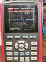
Received this amp. Everything looks fine, until I inject a signal. Current draw is rising, output looks.. See picture.
The first picture is the amplitude at drain, without a signal. The other picture is the output with signal. Never had this issue.

Attachments

  • IMG_20211216_150019.jpg
    IMG_20211216_150019.jpg
    492.6 KB · Views: 87
  • IMG_20211216_145944.jpg
    IMG_20211216_145944.jpg
    509.3 KB · Views: 76

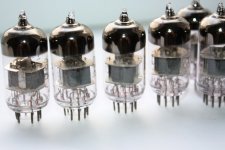
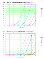
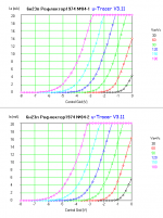
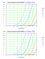
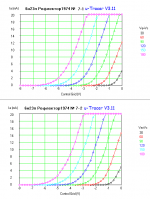
FS: Reflektor 6N23P XI-1974 (= ECC88 /6DJ8/etc.) - NOS - Tested

Hi!

I have in stock excellent electron tubes
Reflektor 6N23P Silver Shield Single Wire Getter Post
All tubes NOS, the same data codes (November 1974).

Each tube was measured on The uTracer 3+

7 psc in stock, price 37 $/pc (for order all 7pcs - 10% off)
payment by PayPal

Best regards!

-------------------
Olexandr
Kharkiv, UKRAINE
skype: OAA-1974

Attachments

  • 6n23p ref 001.jpg
    6n23p ref 001.jpg
    121.6 KB · Views: 595
  • 6Н23П 1974 02.png
    6Н23П 1974 02.png
    26.9 KB · Views: 476
  • 6Н23П 1974 04.png
    6Н23П 1974 04.png
    27.5 KB · Views: 460
  • 6Н23П 1974 05.png
    6Н23П 1974 05.png
    27.1 KB · Views: 156
  • 6Н23П 1974 06.png
    6Н23П 1974 06.png
    26.8 KB · Views: 159
  • 6Н23П 1974 07.png
    6Н23П 1974 07.png
    19.8 KB · Views: 181

Ebay speaker protection board feedback

Hey folks, I thought about buying some IC based output protection relays, similar IC's are used in some older commercial amplifier output protection. What do you think, are they good , have anyone had any experience with these?

https://www.ebay.com/itm/264663559721?hash=item3d9f2d6e29:g:cV0AAOSwIGhgQFrY

https://www.ebay.com/itm/3040842555...h4gQMExbZixuMb0Vly1at2/Ihw==|tkp:BFBMnM260blf

They seem very simple , basically all I need is DC protection in case of amplifier fault and overload or short circuit protection.

Melos 333 phono stage tubes placement

Hello

I have a Melos 333 phono stage which use 2 X 12AX7 and 2 X 6922/6DJ8.
I'm not sure where the 12AX7 and the 6922 go. As is, the 12AX7 are at the output stage and the 6922 in the front stage.
Like it is now, this phono stage doesn't have too much gain with big bass and no treble. I suspect the 12AX7 could go in the front end and the 6922 at output. I don't want to try that because I'm afraid to break something
Thanks

1dB/8va rolloff on 60V passive phono

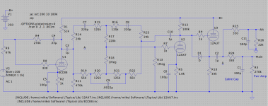
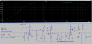
I have been looking at doing a phono stage for quite a while now and having just "retired" I think I may get to start actually playing with it. I had been looking at passive v.s. active v.s. hybrid and was tending toward the later but I have become enamored of the idea of doing a battery powered version using either cordless tool or E-bike batteries. E-bike batteries are reasonably priced in the 36V models but horrendously expensive in the 60V models but tool batteries in 60V seem pretty affordable.

So in that vein I think that passive would be better for battery power as the supply voltage would have less effect on the response than it would using FB EQ. So I came up with this using a two stage FB amplifier front end followed by a single output stage with passive eq in between. Response follows the calculated values pretty closely but there is a 1dB per octave roll off starting at 200Hz. Being less than even a first order roll off I assume that it must be an artifact of the inverse RIAA model I picked up here rather than an actual behavior of the circuit. Can anyone confirm or destroy my reasoning here?

60vpassivephono-png.1007654

Attachments

  • 60VpassivePhono.png
    60VpassivePhono.png
    97 KB · Views: 282

coaxial for MTM center speaker with 2x SB17NRX

I'd like to build MTM center channel speaker with my existing 2x SB17NRX, cross low enough maybe around 350Hz to avoid issues with horizontal dispersion. so the option will be using 5" or 6" coaxial driver

candidates so far :
  • sb16pfc25-4-coax
  • celestion tfx0512
  • faital pro 6hx150

in my short research, it seems using pro driver coaxial have benefit to provide more headroom instead of SB coaxial. i exclude using fullrange driver (i have 1 pair of alpair 10p unused) or maybe other 5" / 6" like fostex or lii audio which has lower headroom

any input will be appreciated, because i rarely find center speaker project with coaxial, majority using midrange + tweeter combination, where low height box is also my consideration. 20cm height is the maximum that i will use because it will be placed under TV

thanks
Projects by fanatics, for fanatics
Get answers and advice for everyone wanting to learn the art of audio.
Join the Community
507,795
Members
7,888,752
Messages

Filter

Forum Statistics

Threads
406,257
Messages
7,888,752
Members
507,795
Latest member
piotechnec