Which Class of Amplifier would this Schematic fit in?
- By hpro
- Construction Tips
- 41 Replies
Hi
Just to make it clear, this Circuit consist alot of a schematic drawn by or designed by Rod Elliot, and also some Parts where Nelson Pass plays a Big role in it, when he helped me out to correct my thinking of many different calculations, with the test Program I use.,
His major speech to me was something like that..
"I'm interested in the real world Amplifier more than simulations" and of course he is right, he's Nelson Pass, the Master of Amplifiers.
Also he showed me the shortcomings, of the last build of mine.. In fact it isn't a shortcoming for me because I designed the Amplifier as it is today, and it turned out better than I expected. The Single End Class A Amplifier from one of my last threads. But there is no playground if it comes to professional Designers and Builders as Nelson Pass and Rod Elliot are. the all has to be by the book. I dreamed of 25 Watts, I got over 30@8 Ohm with THD of less than .5% and less than .05% @1 Watt RMS in my last build..
Of which I have to say that this one just works like a dream and Charm and it sounds real good. Natural...
Mr. Nelson Pass was it, who wrote to me, that using RE a 250 Watts Resistor would lose too much power compared to Power Consumption, and this is TRUE (this in my last build) and that it would be better to stick with Constant Current Source for the Class A. But the levels I listen too are in the range up to max 5 Watts, anything else is just too loud.
But Constant Current Source Class A Amps, I had already done 2013 / 2017 which has again grown out of a design from Rod Elliot DoZ circuit, but which was completely modified by myself. I had sent the modifications to Rod Eliot by email that time, so he knows about this. And this here is the EXTENSION 2021 with some modification compared to that 2 Constant Current Source Class A Amps, I build in 2013 and 2017 respectively, both which are in best condition till today..
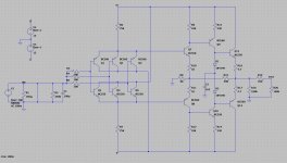
Now the circuit you see I added is a Mix of all these Inputs I've got from Nelson Pass as well as from Rod Elliot's designs and from other sources, many thoughts, I read here, I try to implement here.
I call it Variable Current Class A Amplifier, even I know that there is no VARIABLE CURRENT if it's Class A.
In fact, Adding one more resistor and adding a simple three pole switch can turn this amplifier into a CONSTANT CURRENT SOURCE CLASS A in no time and it can be freely adjusted beginning at 200Milli-amps up to 20 Ampere Idle
The reason to do this (Variable Current Source) is, I try to handle the current when there is no signal on the OUTPUT Transistors, that it will be around 500 / 750 Milli-amp while IDLE but will get full Current on Full Load. So may I can help the ICE BEARS, that the White Gold for them *ICE in the Arktis* will stay somewhat longer..
But I'm not really sure if this still fits into Class A.. that's why here again my Question,
What Class Would YOU put this AMPLIFIER into.??
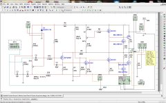
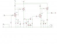
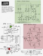
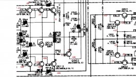
BTW this amp is working on my Bench as you can see it in the Schematic, here.. it has a few add-ons to compensate heat and to keep Super 0.0000Volts at the output at anytime while running.
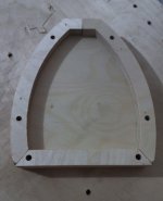
Right now I'm drawing the Artwork, or call it layout for large Heat Sinks, 400mm X 150mm X 100mm.
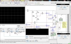
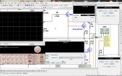
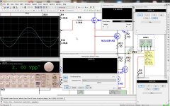
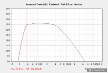
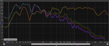
The Design *Simulations* showing 3 versions you can have the read out in that yellow window, once with no SIGNAL at the input but Amp is running idle, and once with 1Khz under Full Load driven into 4 Ohms and then also driven into 8 Ohms and also with Signal switched off.
This way class a could be suitable while in IDLE State, using a mere of 18 Watts while in Idle *depends how high Bias is set too*, about 30 Watts up to 10 watts output and 180 Watt for full output Power. Can this still be considered as CLASS A? More follow soon.
Thanks for any Input.
Regards Chris Hess
Just to make it clear, this Circuit consist alot of a schematic drawn by or designed by Rod Elliot, and also some Parts where Nelson Pass plays a Big role in it, when he helped me out to correct my thinking of many different calculations, with the test Program I use.,
His major speech to me was something like that..
"I'm interested in the real world Amplifier more than simulations" and of course he is right, he's Nelson Pass, the Master of Amplifiers.
Also he showed me the shortcomings, of the last build of mine.. In fact it isn't a shortcoming for me because I designed the Amplifier as it is today, and it turned out better than I expected. The Single End Class A Amplifier from one of my last threads. But there is no playground if it comes to professional Designers and Builders as Nelson Pass and Rod Elliot are. the all has to be by the book. I dreamed of 25 Watts, I got over 30@8 Ohm with THD of less than .5% and less than .05% @1 Watt RMS in my last build..
Of which I have to say that this one just works like a dream and Charm and it sounds real good. Natural...
Mr. Nelson Pass was it, who wrote to me, that using RE a 250 Watts Resistor would lose too much power compared to Power Consumption, and this is TRUE (this in my last build) and that it would be better to stick with Constant Current Source for the Class A. But the levels I listen too are in the range up to max 5 Watts, anything else is just too loud.
But Constant Current Source Class A Amps, I had already done 2013 / 2017 which has again grown out of a design from Rod Elliot DoZ circuit, but which was completely modified by myself. I had sent the modifications to Rod Eliot by email that time, so he knows about this. And this here is the EXTENSION 2021 with some modification compared to that 2 Constant Current Source Class A Amps, I build in 2013 and 2017 respectively, both which are in best condition till today..
Now the circuit you see I added is a Mix of all these Inputs I've got from Nelson Pass as well as from Rod Elliot's designs and from other sources, many thoughts, I read here, I try to implement here.
I call it Variable Current Class A Amplifier, even I know that there is no VARIABLE CURRENT if it's Class A.
In fact, Adding one more resistor and adding a simple three pole switch can turn this amplifier into a CONSTANT CURRENT SOURCE CLASS A in no time and it can be freely adjusted beginning at 200Milli-amps up to 20 Ampere Idle
The reason to do this (Variable Current Source) is, I try to handle the current when there is no signal on the OUTPUT Transistors, that it will be around 500 / 750 Milli-amp while IDLE but will get full Current on Full Load. So may I can help the ICE BEARS, that the White Gold for them *ICE in the Arktis* will stay somewhat longer..
But I'm not really sure if this still fits into Class A.. that's why here again my Question,
What Class Would YOU put this AMPLIFIER into.??
BTW this amp is working on my Bench as you can see it in the Schematic, here.. it has a few add-ons to compensate heat and to keep Super 0.0000Volts at the output at anytime while running.
Right now I'm drawing the Artwork, or call it layout for large Heat Sinks, 400mm X 150mm X 100mm.
The Design *Simulations* showing 3 versions you can have the read out in that yellow window, once with no SIGNAL at the input but Amp is running idle, and once with 1Khz under Full Load driven into 4 Ohms and then also driven into 8 Ohms and also with Signal switched off.
This way class a could be suitable while in IDLE State, using a mere of 18 Watts while in Idle *depends how high Bias is set too*, about 30 Watts up to 10 watts output and 180 Watt for full output Power. Can this still be considered as CLASS A? More follow soon.
Thanks for any Input.
Regards Chris Hess
Attachments
-
 1. Class A - No signal 8 Ohm.jpg178.1 KB · Views: 703
 -
 2. Class A - Full Load 8 Ohm.jpg177.7 KB · Views: 692
 -
 3. Class A - No Signal 8 Ohms.jpg189 KB · Views: 644
 -
 3. Class A - Full load 8Ohm.jpg205.2 KB · Views: 607
 -
 5. Class A - Idla No Signal 4 Ohms.jpg200.5 KB · Views: 599
 -
 4. Class A - Full Load 4 Ohms.jpg205.5 KB · Views: 223


 When I started the thread title one other thread popped up about the 74hc175N but had never got answered.


