Tweeters with Low crossover frequency

Hi,

I just came across this tweeter. What caught my eye was a Fs of 425Hz!!! Looking at the frequency response, I noticed, the freq response is pretty much flat until 500Hz.

http://www.scan-speak.dk/datasheet/pdf/d3004-602010.pdf

I was wondering what your opinion would be about running this speaker crossed really low, say about 700Hz.

There are other tweeters with these specifications

TW030WA05 to 08

I would like to see you opinions on how you think these class of tweeters will perform if used to run with a crossover frequency of 700Hz.

Oon

  • Locked
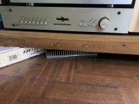
For Sale Elekit TU-8500 Pre-Amplifier

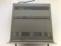
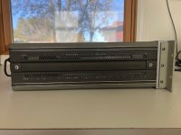
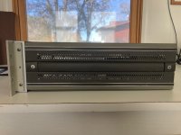
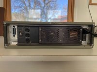
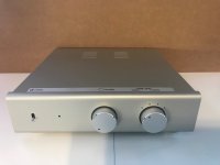
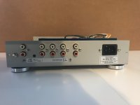
Hi I am selling my Elekit TU-8500 Pre-Amplifier with GE 5965A and Amtrans upgrade resistors. Nicely completed unit in excellent working condition. Selling price is CADS$250 + shipping. Less than 5 hours of use on it. Located in Canada. SOLD SOLD

Attachments

  • IMG_2677.jpg
    IMG_2677.jpg
    414 KB · Views: 187
  • IMG_2678.jpg
    IMG_2678.jpg
    308.2 KB · Views: 208
  • IMG_2679.jpg
    IMG_2679.jpg
    428.8 KB · Views: 198

first attempt at a Salamander

I assemble tomorrow..

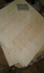
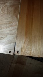
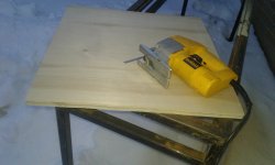
4 shelf system
22"x22" x 3/4" plywood
1/2" threaded rod with poly lock thread
Veneer species unknown, white Maple?

I have some stainless steel I might use to dress up corners. And add a whole lot more strength. Its tough to cut without a water jet. I only have a zip wheel.

Attachments

  • 20220130_213012.jpg
    20220130_213012.jpg
    164.8 KB · Views: 130
  • 20220201_191055.jpg
    20220201_191055.jpg
    338.8 KB · Views: 136
  • 20220130_173545.jpg
    20220130_173545.jpg
    232.8 KB · Views: 125

Streaming/casting Amazon music to Sonos connect or an Iphone as endpoint

Hi All,

I've been using Spotify for many years now, tried Tidal and didn't like it, now I would like to check Amazon music service.
I have a Sonos connect and cambridge audio streamagic serving me as streamers( the Cambridge cannot play Amazon music).
The Amazon music app is installed on my Iphone and configured on my Sonos, when I'm using the Sonos S1 app everything is working and I can control Amazon music playing on my Sonos but I don't like the "interface" of the Sonos S1 app which is a bit limited and dated compared to the Amazon music app.

Is there an option that I can control the music playing on the Sonos from another device using the Amazon music app like with Spotify using Spotify connect feature?

Does anyone knows what is the audio quality that I'm getting when I'm using Amazon music playing on my Sonos (the file/song audio quality is not showing on the sonos app like in the Amazon app)?

Thanks

Hi from Holland!

I just wanted to say hi! I'm Ceko from Holland and I'm starting to get a bit interested to do a DIY amplifier project. But I don't know where to start!
Maybe learn by doing a Amp Camp Amp project first or something. I'm completely new to this all so I'd have to learn how to solder and stuff. I'm also interested in how to measure stuff and make things secure, like not getting electrocuted and stuff 🤣
Well anyway I have a lot to take in so.. see ya!

XR3801

Hello
I'm new here and new to trying to fix amplifiers as a hobby I have some knowledge of electricity so safe in that way.

I have a C-Audio XR3801 which the "soft start" fuse kept blowing, I am currently checking the mosfets...

Came across two j162 where the ohms reading keeps climbing up between source and drain where the others I've tested so far are showing 2ohms as the service manual says...

Is this a faulty mosfet and if so is there a replacement available instead of replacing with j162?

Hope you can help
Thanks.
Luke

Focal 826 Tweeter Removal

Hello,

This is my first post here. I am no voice in building speakers. But I have replaced the drivers in my definitive BP2000/BP7002/SuberCube subs. I recently bought a pair of Focal 826 V speakers. I could not listen to them when I bought them. When I got home and listened to them, I noticed both speakers have tweeter blown. I tried to get the tweeter out by one of the forum member recommendation(using two screwdrivers) and I failed ultimately and damaged it 🙁 . My plan is that remove the tweeters from 826 V and replace them with SR 800 V (surround) tweeters. If anyone can explain the process of removing the tweeters, I would really appreciate. I have attached some photos.


Tweeter inside :
Shared album - Manikandan Krishnan - Google Photos

Tweeter Outside:
Shared album - Manikandan Krishnan - Google Photos

Thanks
Mani

Some ideas on what to do with a Tangband 2" "full-range" driver?

I "recently" purchased a pair of Tangband W2-2243S drivers on black Friday because I had a couple of drinks and they were very cheap.
(newer version of the W2-800SL)
I had thought of using them as a midrange in my MTM towers with dual 6.5" mids and a 1" tweet that could only be crossed at 2,2-3kHz.
But later I realized they don't take much power, and don't reasonably play well under 500Hz. They do have good sensitivity, but not as good as two 91dB/W mids in parallell.

So now. What should I do with them? I could e.g. have use for some small speakers under my triple monitor setup.
But I'd still need some kind of woofers for them that play down to at least 100Hz.
I got them for really cheap, so the woofers should also be free or close to 10€ each.

I have some old sony bookshelf speakers with a 5.25" mid, cone tweeter and piezo.
I also have some Bass Face PAW10, 10" PA mids with a sensitivity of 95-98dB.
Then lastly a pair of ancient Philips speakers with an 8" mid and 8" passive radiator.

From these, the Sony seems like the best bet because they are small, but I'd have to rip up a perfectly good pair of speakers.
I'd also have to fix my TSP measuring system that stopped working with REW some time ago.

But, if I'd get some kind of mid, what kind of enclosure should I make for the 2" fullrangers then?
A tiny t-line could get a flat response down to 300Hz, with a 1st order HPF at 450-500Hz and 1mm Xmax reached with 20W.
I also heard some people used them in a front loaded horn, although couldn't find it. With a horn they might even work with my original plan in making a 3-way MTM (WMTW)
Then some say they work best in a vented enclosure, but I only get a very peaky response with a port, so sealed would be better.

Can I get some Ideas here? I'm open to do anything fun with these drivers really. I have plenty of 9mm plywood which should suite these.

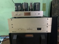
For Sale Conard Johnson pre and power

Hello
I have to sell
Conard Johnson
Power MF2300 (no sound )
Pre PRF ( need to change attenuators)
Selling $900 plus shipping world wide
This pre & power very heavy and
Prefer want to ship south east Asia .
Best regards

Attachments

  • 5AAE7CCC-4DB6-4E31-8649-E81792EA36E2.jpeg
    5AAE7CCC-4DB6-4E31-8649-E81792EA36E2.jpeg
    608.9 KB · Views: 136
  • 53E0F50B-2DC3-48CF-BC6B-11EAADA39B81.jpeg
    53E0F50B-2DC3-48CF-BC6B-11EAADA39B81.jpeg
    467.9 KB · Views: 127

Finally found a sibilance VST that I like

Anyone tried Fabfilter Pro? I'm just trying the 30 day demo and its really good.

I've become very sensitive to sibilance and it got to the point where it would really annoy

me. Simply trying to EQ it out doesnt really work and loses too much of the upper midrange.

I really dont want to spend $170 for the plugin but I haven't found another plugin that

seems to work. Especially with the 'look ahead' algorythm. You can adjust the

amount of sibilance to take the edge of just enough without losing the sense of treble.

I use it in Equalizer APO system-wide.


https://www.fabfilter.com/products/pro-ds-de-esser-plug-in

Modern Mill rice hull sheeting, good for speaker boxes?

Was down at a hardwood store today trying to decide what plywood to get for a build and there was a sample of this Modern Mill board on the counter. Long story short it looks about like MDF on the inside but has a very natural looking grainy look of wood and can be stained with water based stains. I went on the website and found out it glues up with PVC glue . Oh and its pricey. They would order a 4x8 in half inch thickness for $160.

The technical data sheet on it under downloads has all the characteristics of it. It has a density of .65 grams per cm cubed. It is stated to be more insulative than wood both thermally and acoustically.

Anybody heard of it and know if it's good for making speaker boxes?

https://modern-mill.com/

Maximum 'wattage' in one amplifier case?

Hi,

I'm contemplating if I can put all my amplifier boards for my subwoofers and speakers into 1 case, for ease of installation and to keep it 'clean'. A 8+2 sub channel. It would fit very nicely into a Modu 4U Dissipante 400mm case. Buying 2 cases would be slightly more expensive but take twice as much space. 2 cases would have a better resale value, few people will want to buy such a huge case and have dual subwoofers, but I'm building it for myself not for resale.

I just wonder if there is a 'maximum' wattage advised to put into 1 case. It will contain 2 hypex SMPS3K (and 2 ucd2k, 8 ucd400 oem) so in theory 6kW, in practice probably only about 4kW, with a 230V net this would be 17 Amp (my fuse is 25A...and I never had a fuse go with my current setup). Are there any technical reasons not to put too many 'watts' into 1 case?

I would use a Neutrik Powercon and 2,5mm2 wires anyway instead of the IEC. I was going to use a standard Led button (rated 5A) but probably better to make it with a relay if I put it all in 1 case.

Thanks!

oscilloscope-Analog or digital

I need to buy one of these units, and it is my first one so i need something that is suitable for new starters as well as being good enough to move forward with.


I am primarily going to use it, to start with anyway for amp/equipment repairs


I dont have a great deal of room at home so im looking for a bit of advice as to what might be best for me to purchase.


I would prefer to buy new, so i have a warrentee with it


cheers 🙂

Rega R200 Anti Skate Belt Replacement

Just getting ready to embark on replacing the Anti Skate Belt on my 1979/80 Rega Planar 3 R200 Tone Arm.

While there is an excellent article on the how to over on the Vinylengine site, I wondered if any members here had performed this delicate operation and might have some do's and Don'ts or any other tips or tricks not covered in the How to, Such as really useful tools to help get the job done.

Also, does anyone know if I remove the platter and turn the deck upside down, am I likely to get any oil run out of the main bearing? Or is it worth cleaning out the old oil and replacing with some new sewing machine oil, if so, how many drops?.

I intend to put together a fixture to hold the arm in place rather than rely on a combination of mugs and tape as in the original how to, as I suspect some of the pieces are likely to be tight, this way the arm can be supported at all times, so maybe for the main locking collar some mole grips with a strip of rubber wrapped around the collar to prevent damage, the bearing adjuster, it seems can be removed with some round nosed pliers (Which I need to get), again, if someone has been down this road I would be interested to hear your opinions, I might also get a decent tweezer set, just in case.

For disconnection and reconnection of the wiring, which appears to be one hardest things to complete, I thought I could use a threaded rod mounted vertically on the fixture with a large crocodile clip to hold the angled connector in between two nuts and washers which can be turned and carefully raised to reveal the wiring without putting any strain on the fragile wires.

As my eyesight is not what it used to be, I'm also considering buying a USB Microscope for working on the wiring, it will also come in handy should I decide to build anything that uses SMD components.

Like I say, I would really like to hear from anyone who has been down this road and has been rewarded with success.

I'm not interested in upgrading the arm, This is about restoration and putting things back so they may live on for another 30/40 years 🙂

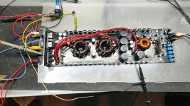
AudioPipe APSM 2000

Hi Everyone, I need a bit of help please with this amp,
Would not Power up, (would just try start but would repeat every second or so and some noise from a transformer)
It had output shorted fets (irf640) and 3 buldged caps. (2 next to battery terminals and one between PS Transformers )
Replaced all output fets with irf640n (gate resistors are 10 ohm) and one was open (replaced it , and all others are good

When powering up one side gets hot while the other is stone cold.(by hot i mean at 40C within 30 secs)
Amp draws 1.6 amps at 11V with signal applied, (but it also draws 0.02A without remote applied (that's probably a indication something is still wrong)
At one stage i had 67v on speaker output, now it stays at 4v (no speaker connected)
The output fets have a not so good looking square wave (see photo)
It doesn't like the 10ohm gate resistors?
The output transformer is getting kind of warm
I would appreciate some help please on what to check/do next .

Attachments

  • IMG20220130111829.jpg
    IMG20220130111829.jpg
    299.5 KB · Views: 141
  • IMG20220203193138.jpg
    IMG20220203193138.jpg
    462.3 KB · Views: 140
  • IMG20220203193903.jpg
    IMG20220203193903.jpg
    461.6 KB · Views: 161
  • IMG20220203194021.jpg
    IMG20220203194021.jpg
    464 KB · Views: 151
  • IMG20220203194027.jpg
    IMG20220203194027.jpg
    384 KB · Views: 158

Logitech Z523 speakers with x530 subwoover connection

Hi everyone 🙂

I bought some speakers today at a thrift shop but my stupid a$$ didn't know that the combination doesn't exist that way. I bought logitech z523 speakers and a logitech x530 subwoover.
The problem is, the speakers cable looks like a vga cable to me and doesn't work with the subwoover because it got less pins.
Any idea how I get that connected?

Thanks very much for your answers in advance, I appreciate your time investment. 🙂

Snoud

Attachments

  • IMG_20220204_040405.jpg
    IMG_20220204_040405.jpg
    216.2 KB · Views: 813

Is my B+ high because I fried something on the board?

Hi All -- hoping for some help in what was supposed to be a simple Power Transformer replacement for my TSE-II. I desoldered C4, and replaced some screw binding posts at 6.3V heater connection. (I'm measuring b+ across R30).

I previously had an Edcor XPWR-008 (300-0-300) with a Triad C17-X Choke (40ohm), and a 47uf C4, and got around 360 B+. I replaced with an XPWR-131 (330-0-330) and Triad C14-X choke (150ohm), and my B+ numbers are all quite a bit higher then what PSUD (which has usually been pretty good for me) predicted: with a 8.2uf C4, I am still getting 415V B+, and with 10uf it's around 425V, and the new transformer is buzzing.

Here's the thing: to troubleshoot, I hooked the old PT back up, and now the B+ is 390V (and that's with the new 150ohm choke in place).

I can figure out how this is possible, unless I fried a component when desoldering? I have been checking things more or less at random, and wondering if anyone had any ideas if there is a particular resistor or cap that if fried would result in this jump? The only thing behind R30 is the choke, which I am getting 150ohm on, so I can't really figure how the B+ is suddenly higher. Would a dead D7 cause this? I would have put a lot of heat on that pad. (Not quite sure how to check components in place though).

The amp will bias up and play music fine (though I haven't wanted to run it too long with the high B+). I'm also wondering if I've simply done something to screw my measurements up, and the B+ is in fact lower? I've tried different multimeters. . .

Any suggestions would be appreciated -- thanks!

EDIT: After some further testing, I noticed two strange things. When measuring the HV secondary on the PT when the amp is turned on, it loops every 5-6 seconds between 700VAC, falling to ~685VAC over a few seconds, and then climbing back to 700VAC. And once the amp is powered off, the B+ drops to 1-2VDC after 2-3 seconds. I remember it taking longer in the past.

Sansui BA60 - One channel higher distortion

You may have read my post in another thread about having a Sansui BA60 on the bench. Well in it's stock state one channel's THD measurement was within spec of the manual, <0.3% at 20 watts. While the other channel was higher at just over 1.0%. None of the original caps were bad but this amp was made in 1970 and anything that old is now suspect.

I replaced all the electrolytic caps with new Nichicons and measured the voltages and they all checked out against the schematic. However the distortion issue is still there. Any thoughts on what could be the cause? I left the input coupling caps as they are they the green dipped film type. My gut feeling is a carbon comp resistor but how to track it down? Perhaps take distortion readings at the various stages? Here are schematics for those interested.

BA60_schematic.png

BA60_power_supply.png

Old Rega Turntable Motor Replacement

Hello,

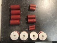
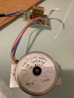
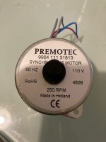
My old Rega turntable has a tired motor hence I got a new Premotec motor to replace it with. I am thinking to replace the old capacitor and resister too while I am replacing motor.

One thing that I am not sure about is if I can still use the same value capacitor and resistor for this Premotec motor. I am based in Australia and main voltage is 230v 50Hz.

Original Motor Serial Number : 9904 111 04802
Capacitor: Rifa 0.22uf 250v MKP cap
Resistor: Not sure what the original value was but when I measure it it shows 14.58K ohm

New Motor Serial Number: Premotec 9904 111 31813
Capacitor: I am thinking to use 2 paralleled 0.1uF, 300vac MKP caps = 0.2uF.
Resistor: 12K ohm resistor?

The reason I am thinking to reduce capacitor value is after reading this post. https://darklanternforowen.wordpress.com/2018/07/13/rega-planar-3-restoration/
According to the post, with slightly lower capacitance than stock, volts balance between windings is much improved and phase delay is not increased significantly.

Should I use 12K or 14K resistor for Premotec?

I have also attached original old motor with circuit board and new motor for reference.

Thank you very much for any guidance.

Attachments

  • IMG_1271.jpg
    IMG_1271.jpg
    49.1 KB · Views: 585
  • IMG_1272.jpg
    IMG_1272.jpg
    39.5 KB · Views: 415

Want to build a Loud & Clear system

I'm looking to build a loud car audio system that will operate on factory power. I'm operating on the premise that I have 1200 to 1400 watts RMS to work with. Firstly is that about right? The vehicle is a 2012 Toyota Wish (JDM) which has a 1800CC 16-VALVE DOHC EFI engine.

With limited space, I'm going with a single 10". I've ordered the Resilient RS-10. [Before I go on, note that all of my wattages will be listed RMS] The RS-10 is 500 watts and will be powered be a DS-18 FRX3.5K, which is 1300 watts at 4 ohms. Overkill, but I got a great deal. The question here is with the gain turned down will the amp more power than a right sized amp?

I've ordered four DS18 PRO-X6.4BM 6.5" 4 ohm Midrange Bullet Loudspeakers (250 watts) and four DS18 PRO-TW120 4 ohm Pro Aluminum Super Bullet Tweeters (120 watts). They will be powered by a DS18 PRO-FR 600.4, which will be ran at 2 ohms, giving me 240 watts per channel. Question is what is the result of wiring tweeters on two channels and mids on two channels as opposed to a mid and tweeter on each channel? Also, I know the DS18's are loud but are they capable of quality sound. I'm a value for money type guy so, if there are better loudspeakers that are a bit more costly, but produce much better sound I'm all in.

Last component is my head. I've purchased the AboutBit Bluetooth Double Din Car Stereo - 7 inch HD Touchscreen MP5 Player Car Audio Receiver – Phonelink | Rearview Camera | AM/FM Radio | USB/SD/AUX | Subwoofer | SWC | Wireless Remote Control. The unit was only $75 from Amazon. Are these inexpensive units capable of producing quality sound or should I purchase a better component if I hope to get quality sound.

HiVi 3.1a Kit Availability

OK, I'm getting lazy in my old age, so I'm looking for a kit where all the hard work has been done for me.
Hence I'm looking at the Swan HiVi 3.1a Kit, which even includes flat-pack cabinets.

However I'm having problems finding outlets.
I live in Australia, but have always used Shipitto in the past, so buying from a US outlet shouldn't be a problem.

Ideally I'm looking for a kit with the Sehlin mode to the crossovers.

Anyone know of any current outlets?
Maybe the actual manufacturer?

android tv box as a network player

Hi, looking at some ultra budget android boxes.
F.ex. X96Q pro.
It uses H313 SoC
- https://www.allwinnertech.com/uploads/pdf/2020040917181739.pdf
It supports several kinds of I2S, bit and sampling rates.

But I cannot really understand what audio I can get through a particular implementation (f.ex. X96 box).
What one can get via HDMI, via spdif and via USB (if possible to connect an external DAC).

Also, is it possible to use it as a player over LAN - both for audio and video files on a PC server.

Regards, Emil

FS: BMR 3-way speakers

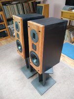
For sale, a pair of speakers built this calendar year. All new components from PE.
Inspired by the Philharmonitor BMR, a pair of active speakers with Hivi RT1.3 tweeter, BMR mid and Dayton RS180p-4 woofer. Cabinets are 3/4” mdf with 13/16” solid red oak baffles. The finish on the mdf needs sanding and repainting to obtain a perfect finish. The mid driver is in its own sealed enclosure similar to the Phil, stuffed with eco core insulation. Fiber glass lining plus polyfill in the main cabinet. Baffles are detachable.
$190 plus shipping buys(your choice):
1. All six drivers in original boxes, except the mids that were in a flimsy styrofoam package. I will do better.
or
2. All drivers as above plus the red oak baffles. This includes the stuffed enclosure for the BMR.
or
3. Complete speaker as pictured.(shipping expensive).
Shipping from 28901.

Attachments

  • 5DED9428-48DA-4452-99AC-B7BEC7FC9F44.jpg
    5DED9428-48DA-4452-99AC-B7BEC7FC9F44.jpg
    736 KB · Views: 582
  • 06E9DFD6-7596-4451-B811-91996CFE89A6.jpg
    06E9DFD6-7596-4451-B811-91996CFE89A6.jpg
    779.9 KB · Views: 500
  • E09656EE-ED60-4F75-9836-0B228C0CA3C2.jpeg
    E09656EE-ED60-4F75-9836-0B228C0CA3C2.jpeg
    484.7 KB · Views: 545

Adding Pre-Outs to an RX-V357

In trying to get a bit more life out of my longstanding Yamaha RX-V357 (B version), I'm looking to extract the surround channels at line-level for which this unit does not have native pre-outs. My thinking is that I can just tap this straight off of the input pins to the STK403-130Y amplifier ICs - where does this logic sit on the scale of reasonable to insanity?

I'm basing this on Yamaha's service schematic, with the block diagram (p53) and main board (p57) showing that this signal should be available over pins 14 & 15 of both IC102 (left channels) and IC103 (right channels). The STK403-130Y datasheet confirms that these seem to be the right pins (for each L/R amp IC - Ch1 is Front, Ch2 is Surround):

Screen Shot 2022-01-28 at 17.27.01.png


RX-V357 Schematic:
https://manualzz.com/doc/o/tpuoa/av-receiver-rx-v357-htr-5830-schematic-diagram
STK403-130Y Datasheet:
https://www.alldatasheet.com/datasheet-pdf/pdf/1314403/SANYO/STK403-130.html
Is there any reason whatsoever that connecting an appropriately shielded cable to these pins won't give me a line-level RCA pre-out for the specified channel?

Building a microphone amplifier

I have a retired microphone amplifier motherboard from BBC. It has ll1538 input transformer, sowter output transformer, class a driver circuit and 5534 amplifier.


Now I want to put it into the chassis to continue its service, but I lack a 48V phantom power supply. I heard that this 48V power supply has a great impact on the recording quality, so I want to build a low-noise 48V phantom power supply, but the commonly used LM317 can only output 40V at most. Is there any other scheme recommended?

Attachments

  • 微信图片_20220120140150.jpg
    微信图片_20220120140150.jpg
    230.4 KB · Views: 190
  • 微信图片_20220120140200.jpg
    微信图片_20220120140200.jpg
    189.5 KB · Views: 181

Newbie with a dumb question

I am thinking about replacing the power supply to my turntable motor - it's an experiment not a necessity, i.e. everything works as is, I just want to "play." I am looking for help to determine the specifications of the existing power supply.

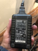
The AC goes through what looks like an SMPS that then connects to an AC power supply at the TT motor. The SMPS, which seems impossible to open, lists three possible voltage outputs, depending on the pins selected inside the case. If I could open the case . . . I could determine the output. The listed outputs on the case are
A) 5V with max amperage of 1.65
B) 12V with max amperage of 0.35
C) 21V with max amperage of 0.38
the motor driving the spindle lists 6A 125VAC.

I am contemplating replacing the PS in the unopenable casing, Unopenable because with lots of force it's not opening. NOT the motor spinning the spindle. I am assuming this is an algebra problem, if the the motor is 6A at 125VAC, that will tell me whether the PS is 5v, 12V or 21V. If I've assumed incorrectly here, I'd be happy to be educated, assuming there is a forum resident willing to do that.

In advance, thanks for looking.

Larry

Attachments

  • PS.jpg
    PS.jpg
    368.1 KB · Views: 139

Newbie: VAS behaving weird in DIGI-125 build

Hi!

I'm attempting to construct the tried-and-true DIGI-125 circuit and I'm experiencing some weird behavior that I hope someone can help me with. The concrete problem I have is that I'm seeing no signal at the Q3 (VAS) base using my oscilloscope. I can see the input signal present at the Q1/Q2 collectors, but there's nothing but a steady -v9.25V DC on the emitter of Q1 when being run from ±10V rails. I have run the circuits on higher voltage rails as well, but this makes no difference. I strongly suspect that I have wired something wrong or have been sloppy in my soldering, but I've now gone through the circuit with a magnifying glass two nights in a row and double checked the transistor pinouts a number of times and still haven't found what is causing these problems. What do you suggest I do to pinpoint the issue?

Points that might be relevant:
  • I'm running BC556's for the long tail pair.
  • I'm running darlingtons (TIP122/127) for the output pair instead of the discrete driver + output device configuration from the schematic.
  • I'm using 1N4148 diodes for the output biasing.
  • I have tried both with and without C3, makes no difference.
  • Bias voltage on the NPN output device (no signal applied) is 0.8V and -1.1V on the PNP output device.
  • DC offset at the output is +20mV.
  • I observe distorted signal on the bases of the output devices and there's also a distorted output from the amplifier.
  • I have checked Q3 (suspecting it was bad), but checking base-to-collector and base-to-emitter using my multimeters diode mode reads ~850mV for both, so no shorts.
  • All transistors are genuine (sourced from Farnell).
Thanks! 🙂

1642810561628.png

Trying to simulate baffle step in Akabak

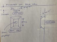
Right now, I'm having a pretty frustrating issue with gmsh -> Akabak where the meshed model doesn't show up properly in Akabak; I think it's on the gmsh end but while I try to sort that out, I'm wondering if anyone can help me run some sims from 100 Hz to 10 kHz for the on-axis response of an ideal driver, including the effect of baffle step from the geometries in the images below? Assume the back wall is infinitely large.

Two sims please, if possible - one with baffle edge chamfers at 30 degrees all around, and one with chamfers at 45 degrees all around. For reference, 0 degrees would be no chamfers, i.e. infinite baffle, and 90 degrees would be like a regular rectangular box.

EDIT: Sorry for the white-out tape, I made some dumb mistakes while sketching in a rush. Never sketch in a rush if you can help it!

Attachments

  • IMG-2461.JPG
    IMG-2461.JPG
    430.5 KB · Views: 154

where to buy affordable output transformers in 2022?

I'm looking for something like these PP ultra linear transformers from triode electronics (22848ULT), but not having any luck getting in touch with them on the phone or by email.

I need roughly 4K UL for push pull into 4/8 ohms. anywhere from 20-50W size will probably do. Application is hifi/audio, but if there are inexpensive guitar amp transformers that are secretly broad band enough to get down to 40-50hz, and up to 20K or more, I'm open to suggestions. http://store.triodestore.com/22bastou.html

Edcor was my original go to, but the idea of waiting 3-4 months is undesirable. The hammond 1650N look good, and are what was used in the original builder's project, but they're a bit out of my price range at the moment. I found these others from triode at half the price of the decors, and they're probably only half as good, but would be fine for experimenting if they were available!

I also found a seller on the auction site, who has these 20W transformers, but they're more aimed at guitar amps. His stock of hifi grade stuff is out of stock at the moment: https://www.ebay.com/itm/154814463681?hash=item240ba93ec1:g:56sAAOSw9-ZeQqiX
I also don't think the 6.6K taps will work as 40% UL taps for.

Any other ideas of where to look?

Improving an old laptop power supply for the Allo Volt+D

I'm wondering which power supply to use with this amp: https://www.allo.com/sparky/volt-plus-d-amp.html

I have plenty of used laptop power supply around, they are probably very noisy,

If I understand correctly the amp's circuit has one of these to clean the noise somewhat:

https://www.allo.com/sparky/capacitance-multiplier.html

I suppose the best would be to still use a decent power supply, but I'm wondering how much noise will be introduced by using an old laptop power supply.

Potentialy stupid question: would adding another capacitance multiplier, on top of the one on the board help ?

TU-8500: Find the bug

TU-8500: Find the bug (found/solved)

I have proudly finished my first build ever – the Elekit TU-8500 tube pre amp.
I consider myself ”pretty good” at building things, but reality bites and truth hurts: I only have sound in left channel. I realise I need help so I will post my debugging here. Please feel free to help. But I warn you, I’m a graphic designer, not an electrician, so my questions will be stupid, ok?

So far, I have:
  • Tested input from all line in and the phono in.
  • Changed cables in and out and also changed power amp.
  • Switched tubes from left to right.
  • Gone over the manual step by step.
  • Resoldered and switched between Jack 6 and Jack 2.
  • Checked for bad solder joints. I’m new, it feels like looking at the Death star.
  • Ordered a new soldering iron (who knows, it might help).
Still only sound from left channel

My plan is to resolder parts on the right channel starting from Jack 6 (pre out).
I have a multimeter but I don’t really know how to use it.
I plan to post pictures.

Help wanted!

Dual Chamber Reflex Subwoofer Revisited

Ok guys,

I am out to build the ultimate high performance yet inexpensive subwoofer for an in house HT room of moderate size.

I have always wanted to do a dual chamber reflex subwoofer based on the experiences I have had from two dual chamber's speakers that I have built in the past which were early attempts at getting good sound.

For a long time I wanted to do a TL because I wanted the fast articulate bass. But it seems that the enclosure is going to be to big for me to deal with.

I have read nearly everything on this DCR (Weem's) speaker topology that I can find and I have come to the conclusion that it's strengths are that it can reproduce bass with less distortion not that it can produce more bass.

However, there are two ports coupling with the room air so it is possible that it might energize the room air more if the driver is up to the challenge of moving the air.

As such I will be using a dedicated subwoofer driver of modest cost.

I have read some papers that indicate that this design typically has a dip in frequency response in the 90 - 120 Hz range so that most speaker designers have found this unusable. At least for a two way design. Also, a three way design would have to have a very low crossover point to avoid this dip which is in a very important range for the lower mens voice. But many designers shy away from a really lower bass crossover point with passive crossover s due to some kinds of electrical considerations.

Yet in theory, this design should have lower mid bass and midrange coloration. So I have to wonder if it is more a manufacturing issue than anything else. I know of one manufacturer that designed a 8 inch two way but sadly I never heard that speaker.

In any case, with an actively low passed signal as in the HT LFE channel these limitations should not be a problem.

The first dual chamber that I built was many years ago when Weem's book first came out and was my first foray into speaker design. At that time I knew very little. It was a two way design with a cheap radio shack 8 inch woofer. It did not put out the kind of bass I wanted but in retrospect it may have been the crappy RS driver that I used in addition to the fact that I was asking too much from an 8 inch driver and was expecting to hear some kind of boom which the speaker did not have.

I few years later I tried to build the ultimate three way speaker. It used a 1 inch dome tweeter and 6.5 inch midrange in it's own large cabinet. The lower woofer was a 12 inch driver in it's own dual chamber reflex cabinet. The speaker was about 4 cubic feet total and three cubic feet were dedicated to the lower woofer and it's dual chamber configuration.

I ended up never finishing the speakers after building the cabinets because I determined that they were way to big for the room I was in and I just could not live with them.

I gave them to my friend who had some ambitions to do something with them but he never did anything with them. I also gave him the 12 inch drivers that I had which were some Gold sound woofers.

A year or so later we hooked the 12 inch drivers in the cabinets all by themselves and drove them with an old Sansui 40 watt reciever as the LFE channel from his HT receiver.

The room was rather large but they were tucked away behind a six foot tall entertainment center in the corner. So the space in the corner was pretty large.

THe room was a tall vaulted ceiling combined with the kitchen which was a pretty big space.

I will never forget watching the Sound of Music. I had not seen it since I was a kid and you would not expect an old musical to have much bass information but those speakers acting as subwoofers had the most profound effect on the movie since they were suddenly filling the room with high quality low fast bass which is rarely ever heard and which I could feel as much as hear.

I have wanted to make 3-4 foot dual chamber sub ever since and I think that this summer I may.

Here is what I want to do to make it rather inexpensive but high fidelity.

1. Self made cabinet of dual thickness .75 inch MDF extensively braced.

2. Good quality long Xmax DVC 12 inch subwoofer from Dayton.

3. I will drive both 8 ohm coils with a separate amplifier from an old stereo amp. Both channels with the identical signal. My theory here is that I will be pushing more current through the voice coils this way which will exert more control over the cone and have the damping effect of both amps.

4. The cabinet volume will be a little larger than optimum and have slightly lower tuning than butterworth to create a more gentle roll off below 30 Hz. This will more closely match with the room reinforcement which will be strong at about 20 Hz and will give me a stonger output at 20 Hz. The room reinforcement for this room should be nearly 6 db at 20 Hz so the way I figure it I should only be down about 1 db at 20 Hz in real world response. This should also improve the transient response of the driver a little by making it behave more like a driver in an infinite baffle.

5. The tuning as I recall from my modelling in WinISD should be about 19 - 21 Hz for the lower F and about 38 - 42 for the upper giving me much lower distortion in these areas.


My thinking is that the dual chamber idea might actually work better for a larger driver with lower tuning since it is at the really low Hz where the driver will create the most distortion. THe reduced cone excursion at the tuning frequencies should reduce the overall intermodulation distortion at the upper bass frequencies and help to make the upper bass frequencies in the 50 - 80 Hz region sound better.

SMD capacitors in active crossovers

Looking at various active crossover designs (especially ones found in cheap powered speakers) I noticed that they use SMD components, including capacitors.
I assume they use ceramic caps since SMD film caps look different and aren't that common. So how do they get away with it? I've always known that ceramic caps are a big no-no in the audio path.

Attachments

  • fKD90qYHmb3s4PSZCmANzCTULmRCGLecpS9dx57L.jpeg
    fKD90qYHmb3s4PSZCmANzCTULmRCGLecpS9dx57L.jpeg
    506.8 KB · Views: 326
  • Like
Reactions: zfuszek

First time amplifier design help, critique, and suggestions

Hey all, I'd like some feedback on an amplifier I'm building. This is my first time semi-designing an amp, so it would be really helpful for me to have more experienced eyes look at it. Buckle up, this is going to be a lengthy post.

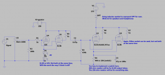
Originally, I was going to build an amplifier based on the schematic shown here: DHTRob - EL3N Single Ended Sakuma style. It uses EL3N tubes as both drivers and output tubes. But the more I researched, the more I went down the "what if" rabbit hole, and have reached the heavily modified design I have now. I have a bunch of changes to the original schematic from that url. Some of them may or may not be good ideas. I'm still learning a lot as I go, so I'm open to constructive criticism.

The ultimate goal with this project is two things:

  1. To have an all-EL3N amplifier like the design from DHTRob above.
  2. Be able to replace my Ampsandsound Mogwai SE by being able to roll the output tubes from that amplifier (EL34, 6L6GC, KTxx family, etc)
Changes to the above design:

  • Able to roll 6J5 drivers instead of EL3N drivers.
  • Able to roll EL34/6L6GC/KTxx tubes as output tubes instead of EL3N.
  • Gyrator loaded input tubes for better support of 6J5. As far as I understand it, I can set the anode voltage with a gyrator. Therefore, I can set the anode voltage to 150 and bias at -4V. This should provide a happy operating point for both EL3N and 6J5 drivers.
  • One chassis design rather than separate PSU.
  • Switch to change cathode resistor for EL3N outputs and other output tubes (explained more below). Switch may also have to switch between different HV secondaries from the PT due to the way lower current that EL3N output tubes operate at.
  • Primarily for headphones. I almost exclusively listen to headphones, but I may also provide speaker outs.
Some specs:

  • OPTs: Custom made 5K:8/16/32. 32 ohm secondary will be used for the headphone jack.
  • PT: HV secondary will have to be custom if I want to support EL3N output tubes. The current draw in an EL3N-output configuration will be much lower than the other potential output tubes (20mA per EL3N output tube vs ~70mA for others), meaning my resulting B+ will be higher. So something like a 0-320-360V secondary with a switch to switch between 320V and 360V can accomodate that.
  • Current schematic: pic attached.
  • LCLCRC PSU for low ripple when using headphones (pic attached).
  • This will be a (almost) no expense spared kind of project. So I'm looking at custom made Monolith Magnetics transformers for this project.
  • Target B+: ~275V
Driver tubes:

Gyrator loaded with anode voltage set at 150V.
Biased at -4V (2 green LEDs?)
- 6J5 driver will draw about 6mA
- EL3N driver will draw about 17.5mA

Output tubes:

Will have a switch for the cathode resistor to switch between EL3N and other output tubes as well as the HT value. I'm hoping I can implement one switch that switches both of those things at the same time.

EL3N
- plate voltage: 275V
- bias voltage: -9.8V
- bias current: 20mA
- cathode resistor: 490 ohms
- Total amp draw: ~75mA (20 + 20 (outputs) + 17.5 + 17.5 (drivers))

Every other output tube (256 ohm cathode resistor):
I designed these with the EL34 as a baseline. So the specs are correct for that tube. The others will vary a bit with plate voltage and bias current than what's shown here because if certain output tubes draw more current with a 256 ohm cathode resistor, the B+ will go down... and if they draw less current, the B+ will go up. This will in-turn affect how much current is drawn (I think!). I'm hoping that I found a happy-enough medium with the 256 ohm cathode resistor that the B+ variations between these output tubes will be acceptable. The only tube I'm a little worried about is the KT88. I might raise the cathode resistor to bring down currents a bit to get the KT88 in maybe the ~80mA range.

EL34
- plate voltage: 275V
- bias voltage: -18V
- bias current: 70mA
- cathode resistor: 256 ohms
- Total amp draw: ~156mA (70 + 70 (outputs) + (6 + 6 (6J5 drivers)))

KT66
- plate voltage: ~275V
- bias voltage: -18.69V
- bias current: 73mA
- cathode resistor: 256 ohms

KT77
- plate voltage: ~275V
- bias voltage: -15.37V
- bias current: 60mA
- cathode resistor: 256 ohms

KT88
- plate voltage: ~275V
- bias voltage: -23.89V
- bias current: 90mA
- cathode resistor: 256 ohms

6L6GC
- plate voltage: ~275V
- bias voltage: -17.65V
- bias current: 68mA
- cathode resistor: 256 ohms

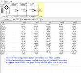
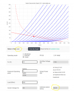
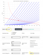
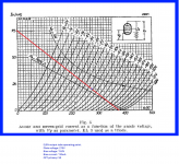
Attached are pictures of the schematic, some of the load lines and operating points for input/output tubes, and an example of a PSU. Again, I'm still kinda new to all this, and there's no way I got everything right on this first try. Any and all comments/suggestions are welcome.

Outstanding questions:

  1. Is a 6J5 or EL3N enough to drive potential power tubes like EL34 or KTxx tubes?
  2. Considering my size limit for this amp: I have room for either a tube rectifier (I like the aesthetic) or a potted choke for choke input PSU. Is a choke input PSU superior enough to cap input PSU to justify having?
  3. Is there any way to estimate the output power this amp will have? I found a couple formulas for output power, and I don't know if any of these are accurate:
- Of Loadlines, Power Output and Distortion.
- The Valve Wizard -Push-Pull At the bottom. Though this is for push-pull, and I don't know if it's applicable to SET amps.
- There's also a power estimate on the universal loadline calculator I used, but the power from that is way higher than the previous two. Not sure if any of these are accurate estimates.
Attachments

  • Schematic.png
    Schematic.png
    74.7 KB · Views: 764
  • PSU_example.png
    PSU_example.png
    32.6 KB · Views: 731
  • EL34.png
    EL34.png
    140.7 KB · Views: 675
  • KT88.png
    KT88.png
    144.9 KB · Views: 671
  • EL3N_output_operating_point.png
    EL3N_output_operating_point.png
    809.9 KB · Views: 826
  • EL3N_driver_operating_point.png
    EL3N_driver_operating_point.png
    799.7 KB · Views: 314
  • 6J5_gyrator_operating_point.png
    6J5_gyrator_operating_point.png
    167.6 KB · Views: 291

Cardioid vs. Di-pole

Had a bit of free time today so started paying with some woofers in a box with a bit of DSP. Aim was to trying to create a cardioid response.

Got me wondering; which has more total sound power output for a given on-axis level, cardioid or di-pole?

I always thought cardioid bass systems made more sense than di-pole in an ideal world because it would closer match the midrange / tweeter polar pattern on a baffle. However today I realised if you have a box with woofers in the front and back some distance apart, say 30cm, the rear woofer needs attenuating more the closer you go to the speaker box due to proximity gain - you (or the mic) is closer to the rear woofer. Conversely, as you go further away from the box the front and back drivers need to be more equal in level.

Di-pole however always has near ideal cancellation on the side axis' because the distance to each woofer is equal regardless of distance.

Kii do a cardioid polar pattern by having the 'cardioid' woofers on each side of the cabinet rather than the back and I now realise that is to get them as close as possible to the front woofer enabling a polar pattern in tighter proximity to the speaker box.

Now I'm thinking mm.. do I add an extra woofer and put them on the sides to go cardioid or go di-pole. Which arrangement actually outputs more sound in to a room for a given on-axis SPL? That is the question that will determine which arrangement has the tightest highest quality bass, I think.

20220203_171957.jpg


20220203_172000.jpg


FYI if I had the mic about 30cm from the rear woofer, that rear woofer needed about -14dB attenuation to get cancellation working.
Yellow - front woofer only.

Cardioid in Garden 1.png


When I put the mic at 1.5m distance the rear woofer only needed -2dB attenuation to achieve cancellation.

Cardioid in Garden 1 1500mm distance.png


(Note did this in my garden. Wind, distant car noise etc probably messing up <30hz results).

HP 8903B Distortion Analyzer For Sale

Hey Everyone,

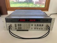
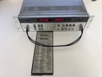
I have an HP 8903B that I'd like to sell. I've owned it for about 10 years now and it has spent most of that time on a shelf in my home office. Functionally it is in good condition. The times where I have used it, I primarily used it for distortion measurements and it has worked great with no issues. At one point I used it with Pete Millet's software of the HPIB interface with no issues. Cosmetically it is in fair condition. There is sticker residue on the front panel, and minor scratches and dents on the chassis. It is missing the feet (I think it is supposed to have feet at least?), but it has the pull out instructions. Take a look at the pictures and I can take more if there is something in particular that you'd like to see. The loopback measurements shown are distortion levels for 20Hz, 1kHz, 20kHz, and 100kHz with 1Vrms generator voltage. There's a lot of functionality I haven't tested, but if there's something in particular that you'd like to see I can check it.
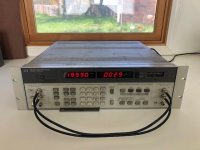
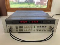
Asking 500 + shipping.

Thanks!

Attachments

  • IMG_1734 - Copy.jpg
    IMG_1734 - Copy.jpg
    70.1 KB · Views: 181
  • IMG_1735 - Copy.jpg
    IMG_1735 - Copy.jpg
    71.7 KB · Views: 171
  • IMG_1736 - Copy.jpg
    IMG_1736 - Copy.jpg
    67.9 KB · Views: 150
  • IMG_1737 - Copy.jpg
    IMG_1737 - Copy.jpg
    71.7 KB · Views: 176
  • IMG_1738 - Copy.jpg
    IMG_1738 - Copy.jpg
    59.3 KB · Views: 150
  • IMG_1739 - Copy.jpg
    IMG_1739 - Copy.jpg
    61.4 KB · Views: 139
  • IMG_1740 - Copy.jpg
    IMG_1740 - Copy.jpg
    59.4 KB · Views: 134
  • IMG_1741 - Copy.jpg
    IMG_1741 - Copy.jpg
    64.1 KB · Views: 133
  • IMG_1742 - Copy.jpg
    IMG_1742 - Copy.jpg
    68.2 KB · Views: 139
  • IMG_1743 - Copy.jpg
    IMG_1743 - Copy.jpg
    82.1 KB · Views: 165

Website or stores for speaker drivers in india

Hlo everyone I am a newbie who just started my diy audio projects.As I am from India I am facing difficulties to buy drivers which are cheap and have parameters. Speaker drivers with t/s parameters and sensitivity ratings mentioned costs much for my budget. When I go into local brands the price is comfortable however they don't have parameters other than RMS value.
So Indians out there please suggest me websites or stores where I can get cheap speaker drivers with parameters mentioned

Thank you

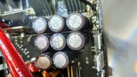
Is This a Super Cap?

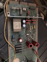
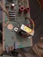
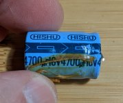
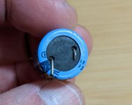
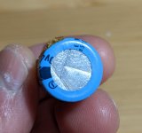
To me, the cap in the photos below looks like a plain jane electrolytic, however, I've seen some super caps for sale on Mouser that also look like electrolytics, rather than the round, button-shaped kind I'm used to seeing. The reason I ask is because the cap shown was in the part of the circuit for an NAD tuner that's responsible for remembering the station presets when the unit is powered off. In this application, I'd expect a super cap (or a coin battery), but this looks like a regular electrolytic and the parts list in the service manual just says "low leakage" in the note after the capacitance and voltage value. Another wrinkle: A different NAD tuner that uses the same IC does use a super cap in this role.

Cap 1.jpgCap 2.jpgCap 3.jpgBackup Cap 2.jpg

AliExpress 5watt Class A ACA clone build

Hi,

Helping a friend with a build. Yes, its for a friend, and not for me 🙂

He bought a couple of the Pass ACA kits from the store here, and for fun, ordered 4 of the AliExpress 5 watt clones so we can do some A/B listening tests.

I have the 4 amp boards, and swapped out three of the caps on the boards as per a mod he found here on DIYaudio for the ACA boards. I have two power supply boards for the build - each one can power two amps boards.

As he is experimenting with bi amping and active crossovers, I need to hook this all up so the are some options when it comes to the outputs.

The idea is to have the amp built with 4 pairs of speaker outputs so bi amping can be done. However, I also want to be able to bridge the boards so I have two pairs of speaker outputs at a higher power rating.

He ordered an enclosure for the hole amp and I'm about to start drilling, but before I do that, I was hoping to figure out the bi amping/bridged wiring option so as to maximize layout efficiency.

Thanks!

Per

IMG_4041.jpeg
IMG_4043.jpeg

Ground plane PCB design for power amps

Hello all.

As some of you have become aware through my recent posts, I have become interested in sucking all the bandwidth I can out of power amps using alternate stability compensation schemes.

I'm sure this is old hat for many of you been-there-done-that guys, but looking at wiring parasitics in the simulator I realized that low-inductance traces are probably necessary to implement alternate compensation with adequate phase margin for stability.

Here is what I think I understand:

1: For a balanced line, the magnetic fields of the signal flowing in opposite directions cancel out and result in lower inductance as long as the conductors are close enough.

2: For a single conductor close to a conductive plane (IE a ground plane), the magnetic field produced by the signal will cause eddy currents in the plane with opposing magnetic fields, again canceling inductance depending on the distance to and quality of the plane.

3: Closer coupling (distance between) traces/ground plane will decrease inductance/phase shift/losses at HF but at the expense of increased parasitic capacitance.

I haven't seen many DIY PCB's using ground plane construction, usually it's just wide traces carrying rails and a ground trace. I think a few of those stratospheric low-THD amps do.

I've searched for information on this but haven't found any. Are there any online pages discussing RF PCB layout?

Thanks,
- keantoken

Class A DIY project with punch

Hi there!
I am fairly new to the DIY scene and have so far only built an ACA, but with great success. I really enjoy the sound of this little amplifier as it draws me into the music like no other solid state amp I heard before. Only thing I miss about it is more authority and punch in the bass region like for example I have with from my NAD C316 bee V2. So after reading a lot about the First Watt F5/6, M2, Aleph builds I am wondering which of these more mature sounding amps with more power is comparable to the sweet sound of my ACA whilst having more punch in the low end? Can anyone help in this regard? Or do I need to choose the honey badger and leave the world of Class A amplification? Thanks in advance!

Help to choose the ultimate midrange driver

Hello

I just registered here and if im posting this in the wrong category i apologize!

I just started building speakers again after many years!
I like active crossovers very much and i decided to order some things and start to build

I first wanted to make a 2 way + sub system

I ordered as below

a pair of Acoustic elegance TD15M
One Acoustic elegance IB18HT

a pair of B&C de250 drivers with a JBL Horn

The B&C de250 arrived first and i didnt like the sound very much, to harsch and to much in my face
I removed the horns and i think the sound improved, maybe less reflection but still not satisfying.

So i ordered a pair of Beyma tpl200, hope that i will like those.

I put the B&C de250 in another system and i am starting to get along with them so they are not totally excluded from the project.

Now i changed my mind and i will make it a 3 way + sub system

I need good ideas to choose the best midrange driver for my system

I am trying out a pair of Dali Oberion ( bookshelf speakers) as midrange, it gives a soft and nice sound which is what i need

i will try the b&c de250 from 1000 to 2000 hz


My question, what midrange driver would i choose for a smooth, very clear and soft sound? I love separation in the sound and it needs to feel super smooth

Some suggestions as below

Cone drivers
Jantzen Audio JA-8008 HMQ
Acoustic elegance td6m
Acoustic elegance td8m
Scan Speak 18 M 4631 T00 - Revelator

Domes
SB Acoustics MD60N-6
Morel EM 1308 Bass-midwoofer
Accuton C51-6-286 CELL Ceramic
Volt VM752 2" Dome Midrange
Atc sm75-150s
Thankful for all opinions


Best regards Marcus

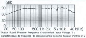
How many dB do the manufacturers consider for publishing bandwidth specs?

Hello all, new to this forum.

I'm trying to compare car speakers from different vendors to upgrade my current in-dash Pioneers, but although they provide us SPL curves along the bandwitdth specs, I haven't found similar detailed information from other manufacturers, say JBL and Kicker. My goal is to improve frequency response (Sensitivity/loudness is secondary).

My current speakers' specs are: 35Hz to 30KHz, which sounds impressive until you notice they consider 20dB drop for that (from 86dB avg to 66dB). But if we look the SPL plot and take, for example, 10db below average, we obtain a more realistic BW of 60Hz to 22KHz.

The JBL's and Kicker's I'm evaluating are speficied from 75Hz to 21KHz and 60Hz to 20KHz respectively, but not a clue of how many dBs below the average that means for them, so I'm not sure if we're comparing apples with apples. Does somebody knows, or where to find such details and/or graphs?

Attachments

  • TS-G1042R.png
    TS-G1042R.png
    243.7 KB · Views: 143

VLT110-4302 Diagnosis and Repair

I have a VLT110-4302 throwing powerfail when connected.

None of the caps appear to be bad, so I checked them as best as I could with a fluke.

The input rectifier seems to be fine, and the main caps both go to 160volts, which seems sane.

The output rails don't turn on at any point.

What steps should I take to diagnose the problem?

Thanks in advance,
bob

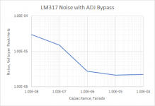
How much ADJ bypass capacitance on LM317

I just ran this test of the effect of increasing the capacitance on the ADJ pin of the LM317 to see what may be optimal. There's little marginal utility in increasing the value above 1uF to 10uF. I could have used more capacitors of incremental values, but that would take more time than is worth investing.

Attachments

  • LM317 Bypass Cap.png
    LM317 Bypass Cap.png
    4.6 KB · Views: 177

L79xx vs L78xx regs - history and makes vs performance

Buying some L7924ct and L7824ct made by ST maybe 10..20 years ago and looking through their datasheet i saw some significant differences in, short circuit current , noise specs and ripple rejection.Looking to newer ON semiconductor (formerly motorola) datasheet i saw less differences in Isc and better noise specs than ST parts.Who's the inventor of these regs? Did anyone found interesting that overall 79xx regs exhibit better numbers than 78xx counterparts?What's your favorite 78/79xx brand make and why?Can you share some thought of their history, different performances in different series or makes?

Pin Ups

I came across a discussion about this on another audio message board.
It's a YouTube upload advertising a calendar, the sales of which are for the benfit of a USA ex-service men/womens' charity.
The models are all ex service women themselves. They make one every year. I thought they were very dignified. It is deliberately made in a "retro" style.

Login to view embedded media

What amused me was the interest shown on the message board, in the vintage radio in the scene featuring Davina.

That's men and their hobbies for you.

Apparently one of the women, Jana served for 20 years as a pilot.

She flew one of these.

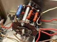
Trying to identify rotary switch type from Heathkit IG-72 signal generator

I'm working on this old Heathkit IG-72, and I'm trying to understand the rotary switches used for frequency selection. Were these switches standard types back in the day, or would each one be custom designed to-purpose? Attached is a picture of one of the switches, and it's exploded diagram. I kinda understand what's going on, but I'm still confused.

Attachments

  • IMG_0066.jpeg
    IMG_0066.jpeg
    406.6 KB · Views: 132
  • Screen Shot 2022-02-02 at 12.07.05 PM.png
    Screen Shot 2022-02-02 at 12.07.05 PM.png
    450.6 KB · Views: 130

Musical fidelity A1 bypass the preamp question

Hi,

I am new to the amp and analogue circuit. I am currently rebuilding the A1. Recap and replace a few transistors and resistors all worked well.

Now I am annoyed by the noisy potentiometer in the line preamp section. I replaced with a new potentiometer, its still making noise when adjust the volume.

So I want to bypass the preamp entirely.

A1 has tape input which is stand alone( marked as “play” I think on the schematic attached below) there is a switch (SW1) between tape input and other inputs to separate them. So I tried to short the line preamp section, by wiring the tape input directly to the power amp input. The intention was so I when use the tape input, the amp acts as a power amp, while other inputs act as the same before.

See picture below:

EA483716-7D21-4A7D-B184-3A5B836B2B58.jpeg

tried it, didnt work well, it sounded very distorted and noisy for some reason.

my question is:
1. What could cause the distortion and noise?do I have to disconnect the line preamp section instead just short it?

2. Can I wire the potentiometer in the middle of the red wire I draw to control the volume?

here is the full schematic for reference

83369373-A152-43B6-8CAB-6A2410E788EA.jpeg

SPST toggle-switch mute - What am I missing?

I mocked up a simple mute switch by putting an SPST on/off switch in-line with the signal on one channel between my preamp and power amp. It worked perfectly, no pop or hum or leak.

When I google for mute switch implementations though, there are all much more complicated than this. I'm sure that's not just engineers wanting to overcomplicate things, so I must be missing something. What flaw is not yet apparent to me in my simple on/off switch implementation?

New Issue Subscriptions not updated after thread split

Although I have a post in the section that was split to make the new thread, it wasn't in my watched threads list. (I have been using the watched threads list, and today decided to look at the bell icon and it's there that I learned the new thread existed.)

So I went to the new thread and in the top right I saw the [watch] button, indicating that I wasn't subscribed.

Screenshot from 2022-02-03 12-33-00.png

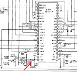
Buffer for Philips TDA1540 CD player rebuild

Hello!
I am rebuild the vintage Philips 14 bits CD player by using Borbely all FET IV stage aS the attached circuit shown.

Anyone can give me a suggestion which buffer should be following this IV stage?

I see something called diamond buffer stage. Is that any good??

Thanks!

Attachments

  • Screenshot_2022-01-31-13-22-37-461_com.miui.gallery.jpg
    Screenshot_2022-01-31-13-22-37-461_com.miui.gallery.jpg
    90.9 KB · Views: 353
Projects by fanatics, for fanatics
Get answers and advice for everyone wanting to learn the art of audio.
Join the Community
507,760
Members
7,887,252
Messages

Filter

Forum Statistics

Threads
406,173
Messages
7,887,252
Members
507,760
Latest member
The Fink