Mark K er18dxt, Myref Fremen Edition, Weiliang AKM DAC , LDR preamp, rpi streamer. Would like to sell all together.

Preamp: https://www.diyaudio.com/community/threads/versatile-and-comfortable-passive-pre-amp.237302/

speakers: https://www.diyaudio.com/community/threads/mark-ks-er18dxt.221806/

I am moving home and selling my pretty much-unused system.
I live in Epsom, South part of London.

If someone is interested in a complete system please pm me.

DSCF2649.jpg

Attachments

  • DSCF2650.jpg
    DSCF2650.jpg
    275.3 KB · Views: 255
  • DSCF2651.jpg
    DSCF2651.jpg
    217.5 KB · Views: 162
  • DSCF2652.jpg
    DSCF2652.jpg
    240.4 KB · Views: 153
  • DSCF2653.jpg
    DSCF2653.jpg
    315.5 KB · Views: 139
  • DSCF2655.jpg
    DSCF2655.jpg
    229 KB · Views: 154

RS100 4 - cone excursion

hello,

I'm trying to design a box for my full-range driver the Dayton audio RS100 4.
my problem is that on WINISD when I try using the recommended box size (from pars express) of :


Optimum Cabinet Size (determined using BassBox 6 Pro High Fidelity suggestion)​


Sealed Volume
0.04ft³
Sealed F3
122Hz

Vented Volume
0.1ft³
Vented F3
59Hz


I get cone extrusion :


1644097882782.png


1644098022231.png

(50W amp max power)

Attachments

  • 1644097952320.png
    1644097952320.png
    22.1 KB · Views: 100

EMI Filter in front of LM3886 for peaks and switching noise over e.g. 40kHz , question about placing the 4,7µF DC Condensator

Hi,
I just build my first LM3886 composite board by my own, to learn, test, measure and all about that.

I do in front of the LM and its composite OP an passive EMI "modul" with OP to filter all about e.g. 40 Khz.
theoretical you see here:

https://www.radiolocman.com/review/article.html?di=335613 FIGURE 2

But Please, do not discuss about that wat I do and ask , I told it in the past, its to learn for my about technical possibilities.😉

So all is now 99% finished, but one last question is not clear for my.

As you all know , for using a LM3886 there is in the front a 1µF up to 4,7µF DC blocker condesator.
Ok, so far, if i use an EMI circuit in front of all ... must I place the 4,7µF before the EMI modul or behind ?

So what is better or right ? Where are the better place for the 4,7µF

--||-- = C 4,7µF

1) AudioInput ...... --||-- ..... passive EMI with diff. OP .... OP of composite LM ........ LM33386

or

2) AudioInput ...... passive EMI with diff. OP ...... --||-- .... OP of composite LM ........ LM33386

or this one :

3) AudioInput ...... --||-- ....... passive EMI with diff. OP ...... --||-- .... OP of composite LM ........ LM33386

kind regards and thanks for helping and discussing 1,2 or 3 ...😍👍

  • Locked
max output 90 to 35hz!

Hi, I need to have as much input as possible below 90Hz.
I have to use 4 subwoofers per side, I cannot carry big and heavy things (we will use the system in establishments with stairs, platforms, sand etc.)

These are my ideas:

1) I currently have 3 tham 15 mk2 per side, but they are not enough, I can build 2 more tham15 and get to 4 tham 15 per side
https://www.martinsson.cc/blog/images/THAM15MKII_BUILD.JPG

2) I have 8 turbosound tsw118 witheout driver (I don't know if the exact name, but it is the sub with the curve, ie identical to the lower part of the tms4) I could put the recommended PD cones with 4 "coil but many speak of poor efficiency at the bottom, Does this problem exist even in groups of 4?
https://i.ytimg.com/vi/OWuLN5mF_NE/maxresdefault.jpg

3) build tham 18
https://i.ytimg.com/vi/oisGNpC3M0A/hqdefault.jpg

4) build the new paraflex, but in compact versions. both from 15 and from 18
https://i.ytimg.com/vi/KRdBzvFJtY4/maxresdefault.jpg

5) recommend something suitable for the purpose 🙂
--- consider that the dimensions of a cerwin vega L36 are already too much: D ---

in short, which one makes more from 90 hz down, I don't need 20hz but an extended response up to 35 / 40hz pretty powerful!
I have already tried to ask but it creates a lot of confusion that top speakers use, etc etc ..
if you have simulations they are welcome!

thank you all!

Modern Day "Bose 901" Type Speaker?

What are the possibilities for a modern day Bose Type "901". Just wondering if you use more modern and well built full range speakers and a MiniDSP unit. Front DSP would be different from rear DSP output - say use a 4 channel DSP... Use built in amplification via CLASS D.
What might the possibilities be? I have some extra 3116 and a TPA 3251 Aiyama and a miniDSP 2x4HD for testing concept
What drivers might be considered?

How to calculate the least feedback resistor value for an op amp

Hello all,
I have been searching for a reference or an article on how to calculate the least amount of op amp’s feedback resistors for the benefit of noise. I noticed that there is a specific reference and chart on AD797’s datasheet which recommends “100 ohm”. But how can I chose the resistor value for LM4562 or other ones for example? I would appreciate if you may help me or share a reference on this matter to me.

Yours,
Alan

Running ac and dc power together

Greetings everyone, noob here from downunder.

I have a question about a small installation I am helping a friend with.

It's in a very cramped space with no power outlet so we decided to use components run from plugpacks located in the next room with leads going through the wall cavity as one bundle.

All good but now I realise that some of these plug packs are ac and some dc, but all low voltage.

Finally to my question - could there be interference from the mix of ac and dc lines particularly for the turntable and phono box?

If this was easy I would just try it out but the installation really is a nightmare plus the walls are asbestos.

Thanks for looking, mouse

EF86 do change tone!

Hi, I have been around listening to music all my life. In the last 10 years I have owned vintage Quad II's. I have been very happy with the sound quality as it is excellent. I am now at the point where vinyl is superior to CD in most cases. I am now experimenting with swopping out valves. There is a definite tonal difference when having removed the Mullard EF86's and replaced them with four new old stock Bentley Acoustic valves (foreign made). I have tested them out on various recordings I have known for a long time, the differences are (with the Bentley's). Slightly reduced bass volume, a more 'spacious' sound, wider stereo response, very detailed and clear tops (incredibly so). On some of the records I have just listened to I heard acoustic guitars, triangles and hand claps for instance far more clearly than ever before. (all settings are flat). It's fascinating to me that such changes make things 'different'. I know I am hearing it differently, it is not an illusion. I am 65 years of age and have owned some of these records before I was 10. To be able to keep on getting more and more out of them is really great. Has anyone out there had/or having a similar experience?

Tube to tube variability

Hi all,

What do you consider a "normal" level of mismatch between two new unmatched KT88's from the same Russian manufacturer (EHX)?

Maybe I've just been lucky, but to date most pairs of EL34's and KT88's I have used have biased within a volt or two of each other. Measured THD between channels is typically equal to within fractions of a percent.

The other day I installed a brand new pair of unmatched Electro-Harmonix KT88's which were purchased from the same store. One of them self biased at -46V and one at -50V. One channel displayed 1.2% THD @ 1W, the other more than double at 3-4%. Swapping the tube positions confirmed it was the tubes, and another set of JJ tubes self biased nicely at -45V with near identical THD figures (1.2%).

Maybe I have just been lucky, but to date the difference between the two EHX tubes far exceeds the variability I have become used to. I suspect the high THD tube may be faulty or damaged in transport.

Any thoughts?

End table sub build

I am remodeling my great room, bringing in two La-z-boy recliners, getting rid of the couch. This is also the room I watch TV most often in. The speakers are in-walls and the TV is a super neatly installed low profile samsung. In short, I the AV setup is understated, but I do not want to compromise on performance. I want to replace the in-room sub with two custom built end tables to put by the recliners, that actually serve the job of end tables and subs.

I have two Ascendant Audio (now defunct) Atlas 12's and PE 250 W amps that have been sitting on the shelf for a decade and I never got around to building anything with them. At this point I am thinking of using the Adire Shiva plans for 88.5L sealed configuration. https://us.v-cdn.net/5021930/uploads/attachments/2/2/9/7/4/16273.pdf

For a finish, I was thinking of doing a live edge waterfall style table look, with the sub inset into the slab on the front. I'm not sure if my woodworking skills are up to that precision though. Alternatively I could have the live edge go the other way with a waterfall down both sides, but I think the contrast between the edge and the sub will seem less striking.

Finally, I do not know where to mount the plate amps. I do not want to have them external, so either I cut a hole in the back panel and mouth them there, or I create another amp chamber on the back of the box, separate from the sub chamber. I do not know how much of a difference the plate amp in the sub chamber vs. a separate chamber makes. Could use advice.

Thoughts on my plan? Any suggestions?

Tripath TA0103A to TA0104A modification

Not sure how useful this information will be to anyone at this point, but I might as well share my findings since I already did the work.

A little backstory first. I bought three Audiosource AMP Seven T amps back in 2007. They had a habit of blowing the FETs and TA0104A module if you so much as looked at them wrong. Putting in a new module without replacing the failed FETs would instantly kill the new module. They ended up killing 7 TA0104A in total (the 3 original plus 4 replacements), so I put them on my "shelf of shame" and left them there until recently. I wanted to give one last go at repairing them, but the only sources for TA0104A at this point are Aliexpress for $90 or Audiosource on eBay for $110. Knowing how fragile they are, I wasn't willing to spend that kind of money.

I've taken the plastic covers off of most of the modules that died, and it appeared to me that the only difference between the TA0102A/TA0103A/TA0104A was probably some passive component values, but I didn't have a TA0102A/TA0103A to compare. I recently saw a listing on ebay for 3pcs TA0103A for $30 and quickly bought them (they can be found on Aliexpress for around $35 each). I popped the cover off of one and compared it to a TA0104A. I noticed a handful of resistors with different values and proceeded to swap them out. After doing a few other mods/repairs to one of the amps, I popped the modified TA0103A in and powered it on. Success! I now have at least one working amp again.

Anyway, here are the 1206 resistor values that need changed...

1.05K - R5, R18, R20, R21
4.99K - R52
19.8K - R35, R48, R49, R50
680K - R53, R54, R56
2M - R55, R59

I should mention that there are also 10 light purple colored 1206 ceramic caps that I just took a chance on being the same. I removed a couple and tried to measure them, but my meter only goes down to 1nF.

Bipolar Elkos in Feedback line?

Hello Folks,
I want to recap an old classic integrated amp (HiFi 50) to bring it back to his original performance. In the signal path there are standard polarized Elkos which I want to replace with bipolar Elkos (Nichicon Muse ES).

My question is does it make sense to replace also the Caps in the Feedback Line (C9 100uF/16V) with the bipolar type?

Thanks and Best Regards, Uwe

Attachments

  • D04EE2F9-5EFE-4BF8-977B-E700A4D62547.jpeg
    D04EE2F9-5EFE-4BF8-977B-E700A4D62547.jpeg
    231.7 KB · Views: 164

Leonids Voice Master variant, or CS10?

Hey guys,

I’m contemplating building a variant of the Leonidas VM, but instead of the F15+W15, I was going to use the F12+W15. I was planning to use the standard leonidas xo, but there are a couple of „but“‘s in there.

First of all, I was hoping to create a baffle from one piece. The VM used two baffles on the same frame with 5mm discount if I recall correctly. Soo I’m not sure how a a single baffle would affect things, or should I keep two separated baffles?
Also, the F12 I read on the forum ideally uses a baffle of about 40x80, whereas an F15 would use something bigger. What would be the best baffle dimensions for my variant? (Or how can I find out)

secondly, the F12 is a bit different from the F15, soo I’d imagine the xo could do with tweaking as well. Any suggestions how to best tweak that?

finally, I heard the cs10 speakers with the Crystal 10, and percussion sounds amazing. Bass not very deep but enjoyable and percussion did very tight and controlled. Of course this was not a live test. I am curious if I can achieve a similar sound with my setup. Perhaps with tweaking the side wings and the xo?

Preamp bias voltage is smaller than it should be

I'm trying to diagnose an issue with a Sony TAE-F20 preamp. The preamp has a very noticeable hiss even at zero volume, and volume increases far quicker than it should when the volume is turned up from zero. The balance, volume and tone pots generate scratching. All of this points towards a problem with DC bias, which is visible on the output lines.

I downloaded the service manual, and have taken measurements at the points specified. A few things stand out:
  • The voltages on the main opamp ICs are out of spec, probably due to power supply issues
  • the +31V and -31V lines are running over spec, at 32.7V. This is probably because the preamp is rated at 220V and the power here is 230-240V - but it should be able to cope with that.
  • One particular voltage is way off spec - the collector on Q401 is reading -21.3V when it should be -24.5V. My best guess is that this is the issue that's causing the preamp to misbehave.

I've tested the resistances across the transistor Q401 and both show around 800 ohms, which suggests that the transistor is not broken.
I've checked the resistances of nearby resistors R404, R405 and R406 and they are within a couple of percent of spec.
I've checked D402 and it is a 1.2V Zener diode which my component tester says is behaving correctly.
I've checked C402 and my component tester reads a capacitance of 110uF in situ.

Q401 is a 2SC1364 transistor, which the spec sheet says is NPN. The collector on Q401 is connected to the base of four output transistors (2SC1636, also NPN), and to a 1uF capacitor to the negative output terminals. I've checked all four output transistors and they're behaving correctly too (same as my test for Q401).

What could be causing this incorrect voltage? There are no obvious visible faults on the PCBs. The tools I have at my disposal are a multimeter; an SMD tester which can check capacitances, resistances, and the behaviour of diodes including Zener diodes; and a basic digital oscilloscope. I have the full service manual with circuit diagrams and PCB layouts. Any ideas?

1642674931654.png

  • Locked
For Sale Elekit TU-8200R Part Out

Hi, I am selling my “ DEFECTIVE” TU-8200R, part out or complete unit without tubes.

It has been built with all Amstrans and carbon resistors.

There is a hummm noise that I can’t fix. If power on with headphones plug in, it plays ok without any noise, just perfect. However if the headphones are unplug reverting to speakers or the unit started on speakers then there is this background noise humming and some gritching noise.

It worked perfectly until I did tube rolling with a pair of EL34 tubes. First power on with those tubes it blew one resistor, 4 capacitors and 2 FET. Those have been professionally replaced but I still have that noise.

If anyone is interested I am selling the whole unit, without tubes, including the USB-DAC module as shown on pictures.

I am asking for the whole unit $160 CDN + shipping

Shipping within Canada is $40, shipping in USA is $60.

If you want specific parts, like the complete casing, maybe for a new paint job, or any other components, please let me know and will work out a deal.

If you need more pictures or details pls, just let me know. Located in Canada

Attachments

  • IMG_2682.jpg
    IMG_2682.jpg
    421.4 KB · Views: 119
  • IMG_2683.jpg
    IMG_2683.jpg
    309.3 KB · Views: 122
  • IMG_2684.jpg
    IMG_2684.jpg
    523.2 KB · Views: 127
  • IMG_2687.jpg
    IMG_2687.jpg
    512 KB · Views: 121
  • IMG_2688.jpg
    IMG_2688.jpg
    495.9 KB · Views: 116
  • IMG_2689.jpg
    IMG_2689.jpg
    560 KB · Views: 121
  • IMG_2690.jpg
    IMG_2690.jpg
    446.6 KB · Views: 119

Volume for a sealed enclosure with a FaitalPro 3FE32

I want to build a small violin amp, with two FaitalPro 3FE32 drivers, each in a separated sealed enclosure compartments.

I've used the calculator on this site to calculate the optimal enclosure volume:

https://www.diyaudioandvideo.com/Calculator/SpeakerBoxEnclosure/

It gives me a the following:

Vb = 0.46 liters (0.02 ft3) (Speaker Box Internal Volume)
f3 = 216.06 Hz (3dB Cutoff Frequency)
fb = 216.03 Hz (Enclosure Resonant Frequency)

The parameters I entered were (Vas = 1.3 lts, fs = 110 Hz, Qts = 0.36, Qtc = 0.707)
(Not sure if I chose the right Qtc)

On the parts-express site, it suggests a volume of 0.01 ft3 (0.28 liter, wich would give a sealed F3 of 244Hz) :

https://www.parts-express.com/FaitalPRO-3FE22-3-Neodymium-Professional-Woofer-4-Ohm-294-1100

I then used this other calculator: http://www.mh-audio.nl/Calculators/CBCV.html

Which shows me a response curve given the thiele-smap params, and the desired volume.

I'm not too surprized that the calculators don't all agree, but they are kind of far appart (0.46 vs 0.28 liter), and the volume seems pretty small, and I'm not so confident I'm using the calculator correctly.

Diamond Buffer variations

As I shown, there are some variations about the Diamond Buffer.
The first Diamond Buffer comes from Walt Jung.
https://web.archive.org/web/20161130160711/http://waltjung.org/PDFs/WTnT_Op_Amp_Audio_2.pdf

Some variations from here:
https://www.diyaudio.com/forums/power-supplies/297921-jumas-easy-peasy-capacitance-multiplier.html#post4855801
https://www.diyaudio.com/forums/headphone-systems/271545-cfa-headphones-amplifier.html#post4267008
https://www.diyaudio.com/forums/headphone-systems/376909-headphone-amplifier-design.html#post6783348

It is noticeable that the collector of the input transistors is no longer connected to the power supply, but to the emitters of the output transistors. What advantages does this bring?

Attachments

  • WaltJung Diamond Buffer.png
    WaltJung Diamond Buffer.png
    377 KB · Views: 2,860
  • Juma_ha-F5-BJTin.gif
    Juma_ha-F5-BJTin.gif
    7.9 KB · Views: 2,611
  • arpagon_Diam_Buffer_THD.png
    arpagon_Diam_Buffer_THD.png
    175.5 KB · Views: 2,266
  • HPA Buffer.png
    HPA Buffer.png
    120.6 KB · Views: 2,546

A12 vs A50

Given all the work and time I have spent with the Reisong A12 and the Boyuurange A50, I felt there would be value in comparing the two. Neither of these amps sound good out of the box and it required quite a bit of rewiring, changing operating points etc. to make them sing and perform as advertised. I would say that neither of them are better than the other out of the box, so if you plan no mods, buy the cheaper amp (or honestly, something else!).

Both can be made to sound much better using the mods I have previously posted and describe on my YT channel. That brings us to this point, in the end, which is better and why?

IMHO the only reason to buy the A50 over the A12 is to be able to say you own a 300B amp and to display a larger amplifier. The cost to upgrade the A50 includes replacing all the tubes, which as most people know, 300B tubes are EXPENSIVE. By the time you buy the amp, do the mods needed for it to perform as advertised and then replace all the tubes (which is needed) to even decent quality ones, you will have close to $1500 into it, and it's still being held back by the lackluster output transformers.

If you dive into replacing those, which probably will require fabrication work, which is hugely difficult on a chromed stainless steel chassis, you will have close to 2 grand into this amp. And at that point what is even left of your original purchase? The chassis, the power transformer and a few jacks? You would be way better off doing a scratch DIY build like my budget 300B amp, even if you had to pay someone else to do the fab work for you.

The A12 on the other hand comes to life with mods + $75 worth of tubes and less that $30 in other parts. You can actually use the A10 as the starting point, since we are rewiring the front end and everything else is identical to the A12, saving you another $75-100. The output transformers used on these little brother amps are a much better match to their EL34 tubes and as such, have more bass, less distortion and a smoother frequency response. Modified, this amp sound surprisingly good, especially considering it's price point.

I've listened to both modified versions of these popular made in china amps quite a bit, and while the A50 might have a very slight midrange smoothness advantage, the A12 crushes it everywhere else. They have very similar power levels and given all this, with the 10X cost difference in the output tubes, plus the initial buy/mod cost, it gives a huge swing in favor to the smaller sibling. Even not considering the cost, the modified A12 overall is just a better sounding amp.

So in closing, I now can honestly say: If you are a tube noobie and can DIY these mods, the Reisong A10/A12 + mods gets you into a new, good sounding single ended amplifier for well under $600 all in. That is going to be hard to beat and the only shame is, this amp isn't wired like my modified amp is out of the box.


Login to view embedded media

How to professionally cut and apply aluminum traces to mylar?

Hi there!
I'm trying to build a planar speaker and ideally I want to use super super super dense tracing (0.0762mm trace width, 0.0762 mm spacing).
I can do this with flexible PCBs but the diaphrams they offer are not thin enough.

How do companies do this sort of thing? How do you professionally cut ultra thin alluminum and apply it to mylar?
I can etch my own alluminum and possibly attach it myself but how do I cut it?
I'm willing to spend some money on some special equipment if needed but I don't know what that equipment may be.
Would appreciate any ideas thrown at me 🙂

BG Neo10 and neo3 for MTM monopole design

Dear all,
I'm planning to use BG planars Neo3 and Neo10 remained from previous classical projects, for an SW-MTM-WS 4 way active design. Dayton RS225-8 and Peerless P830668 should be the woofers and subs (side firing) of this new project, respectively. Since it will be my first MTM speaker with such kind of drivers I'm worried to commit some errors due to my inexperience.
In your opinion are these drivers suitable for a monopole MTM designs? The Neo10 length (250 mm) may represent an obstacle? The TM CTC distance should be approximatively 175 mm with MM CTC of 352 mm.
Finally, according to your experience, what XO frequency and slope should I use?
Any other comment or advise will be greatly appreciated.
Cheers

DC resistance or impedance of output transformer?

Hi guys!
I have a maybe stupid question but still I would really apreciate if someone would answer it to me. When I am setting an operating point of the power tube, as a plate resistor should I be counting with the dc resistance of the primary side of the output transformer or it's impedance? In my case the dc resistance is 170R but the impedance is 5k. Thank you.

For Sale Accuton C25-6-158 tweeters

2 pieces Accuton C25-6-158 high end tweeters. Only briefly tested, very good condition (9/10), in original box. Datasheet: https://accuton.com/home/produkte/lautsprecher/keramik/Keramik-C25-6-158-CELL Cell technology, underhung voice coil, very low distortion.

Price: 250 Euro each.

Shipping is paid by the buyer, location: Germany.

Attachments

  • 20220205_135844.jpg
    20220205_135844.jpg
    417.2 KB · Views: 56
  • 20220205_135801.jpg
    20220205_135801.jpg
    618.4 KB · Views: 59

Which MID for 3-way system : SB12MNRX2-25-4 or Visaton B 80, 8 ohm

Looking for a mid driver for a 3-way system.

So far the search came down to those 2 drivers.

Visaton B 80, 8 ohm or SB12MNRX2-25-4​

Dont know if one have experience with both these drivers.
Or maybe some can say which they prefer for which reason.

Mid will be crossed around 300 - 3K .
There isnt much between them I guess.
Visaton + : 8ohm, smaller, lighter
- : sensitivity = 85db. (woofer used is SB23NRXS45-8 88.5db)
SB acoustic + : sensitivity =90db
- : 1"bigger, 4ohm

I dont have any information about off-axis and distortion....

https://en.toutlehautparleur.com/parametres-thiele-and-small/

[Moderator edit: Removed malformed table]

4/8/16 Ohm Dual Dummy Load

I had a reason to drive a modest power amp into clipping in a dummy load and I came up with this. Those are not
low inductance resistors, just wirewounds by Ohmite but they can tolerate 100 watts into 8 ohms, 200 Watts into
4 or 16 Ohms. The channels are totally independent so it can be used with nearly any amp. The shorting plugs are
captive so they don't get misplaced. All the resistors are 16 Ohm 50 Watt. It's not fancy but is useful now and again.

Attachments

  • power amp load.jpg
    power amp load.jpg
    136.8 KB · Views: 343
  • P1060262 shorting plugs out.jpg
    P1060262 shorting plugs out.jpg
    272.1 KB · Views: 387
  • P1060261 shorting plugs in.jpg
    P1060261 shorting plugs in.jpg
    269.7 KB · Views: 373

Cromo 12 woofer problem

Hi

I am working on this db Technologies Cromo 12 powered speaker. The tweeter works fine, but the woofer has no music output, it has a motor-boating sound. I have not dismantle the amp and check anything yet. I want to have an idea what probably can be the fault before I dismantle the circuit. Can it be the TDA8950. Can someone give me a clue. I cannot get the schematic.

Thanks

Carlos

Technics SB-10 Crossover Questions

Greatings Ladies and Gentlemen,

This is my first post on diyaudio🙂

I have just been happily reunited with a pair of Technics SB-10 speakers and a Technics SU-V9 amp.
I had the same equipment back when they first came out, so when given the chance to acquire again I did not hesitate.

I since have been reading about vintage equipment and how the capacitors decay over time.
I see this as a opportunity to upgrade those electrolytic ones that can cause problems.
The speakers will be a lot easier to attempt so I will start there first.
After a week of reading on the net I am a "little" bit more knowledgeable, but need a few hints;

There are three electrolytic capacitors in the crossover on the Bass circuit;
One 47uF 100v electrolytic in parallel with a 0.47uF 100v metalized polyester film C1 and C2 on the diagram. (is this configuration called a bypass?)
Two 330uF 50v in parallel with each other and in series with the Bass speaker.C8 and C9.
The 47uF 100v appears to be an easy swap for a polypropylene film cap of the same 47uF value but 250v. I am thinking of using the Clarity Cap CSA would this be a good choice?
When it comes to the two 330uF 50v electrolytic caps I am stumped, there does not seem to be a match in a polypropylene film type. Probably have trouble fitting them in anyway.
Should I just use quality electrolytic caps of the same value? If so any suggestion on the maker?

Below is a schematic of the crossover, (hope it is legible) any advice on the design and possible upgrades would be a great help as my knowledge in this area is not great. I would appreciate any advice given.

Best
Regards
A confused
Technics SB-10fan

Specifications
Type 3way 3 speaker system
Woofer: 32cm honeycomb dicc
Midrange: 8cm honeycomb disc
Tweeter: Leaf Tweeter (full surface movement type)
Impedance: 8 ohms
Input Power: 150 W, Music
100 W, DIN
Output Sound Pressure Level: 87 dB/W ( 1.0 m)
Crossover Frequency: 400 Hz. 4000Hz
Frequency Range: 28Hz~125 kHz (-10dB)
Dimensions: 40.2(W) x 71.1(H) x 31.8 (D) cm
Weight 32.0 Kg

Advice requested regarding Auto Bias for tube amplifiers.

Good day everyone.
Please advise on the following. In principle, the question generally applies to tube amps for guitar, but in this particular case I will take the example of the Mesa Boogie Dual Rectifier.
In many cases it is already possible to adjust the bias for the power tubes yourself by means of a trimpot. An example is the Marshall JCM2000 series.
However, at Mesa they believe in fixed bias. By default nothing can be adjusted by the user and Mesa would like you to buy the tubes through them. This means that nothing more needs to be adjusted.
Now it is of course possible to include a trim pot in the current design, so that it is still possible to adjust the bias yourself.

But now I came across the following.
https://www.audioamp.eu/module-ab-q...3vac-filament-supply-is-referenced-to-ground/
Module_AB_Qi_for_4_tubes.png


This makes it possible to set a bias that is desired. This circuit then regulates the correct bias voltage for each tube.
The advantages according to the manual:
The advantage of using the AB-Qi module is that it will extend output tube life, in a lot of cases it will also improve the sound and last but not least, you will never have to worry about adjusting the bias again.
• Instead of a pair of output tubes being biased together, now all output tubes are individually biased for greater control and stability
• No need to keep an eye on and/or adjust the bias of the output tubes
• Significant extension of the output tubes life
• Bias is not influenced by the input signal
• Undistorted and improved sound for a great listening experience
• Reduction in hum and noise level of the amp
• No maintenance or additional adjustments are required after the initial setup
• Improved overall operation of the amp due to the reduction in the danger of a tube red plating
• The AB-Qi ensures that bias is kept at the pre-set value (see Initial Setup) even as the tubes age
• The AB-Qi comes with a soft start feature, which slowly brings up bias to each output tube
• The AB-Qi comes with its own 6.3VAC to12.6VAC isolation transformer, designed for use in an amp where the filament supply is referenced to ground

Now I have gathered some information about this and have adapted the schematic accordingly.
Below the original and below the modified schematic.
Besides the benefits that the designer claims, I would like to achieve the following with it; I would like to decide for myself which “brand” tube I want to use. So I don't want to be dependent on Mesa. In addition, it should also be possible in this way when a tube is destroyed, I do not have to order a quartet of tubes immediately, but because of the separate bias I can only replace the fallen tube.
Does anyone have experience with this system? What are your ideas about this? Will this work (well) or will it cause a lot of problems? I like to hear it.

Original:

Origineel.png


Modified:

Modified Bias.png

For Sale TOKIN THF-51S

SOLD SOLD SOLD SOLD

I have a rough matched pair(No data) of TOKIN THF-51S SIT's with mounting kit. I purchased these from Watanabe-san on Ebay in anticipation of building another amplifier. I just finished a Singing Bush amp which uses the THF-51S SIT's, so I really don't need another amplifier.

Price is $170 (PayPal friends and family) or $175 PayPal plus shipping, your choice since you are paying for it. I prefer USA, however, if you must, I will ship outside USA using DHL ONLY!

Attachments

  • IMG_2265.JPG
    IMG_2265.JPG
    464.6 KB · Views: 120

PCB Layout

Hey Guys,

I've just put together my first PCB and I was wondering if there was anything major I've missed or messed up. It's all working on a beard board and in still laying out the power regulators and supply on a separate bread board. This board contains -> TL071 Buffer -> LM1875 -> Output Mute relay controlled by a 555 timer. Pots and LED's are all of board hence the pads.

I've tired to keep all power on the bottom layer and signal on the top, but there are short vias here and there to get over tracks. the Audio and Power grounds will be star grounded.

Anything of major concern here?

Schematic.png
Combined.png
Top.png
Bottom.png
Components.png

Differential pair basis' currents and amplifier stability.

Analysis and study of amplifier stability.

The issue of instability arises when an inverting signal becomes such that it helps the input to cause more change in the output. An inverting signal should always work in opposition with the non-inverting input, so that, the differential input or equivalent, work like a balance with as little offset as possible depending on amplifier open loop gain. The output is guaranteed to mimic the non-inverting input in shape as long as the inverting inputs continues opposing the input. However, electric current and voltage may not be in phase. This difference arises everywhere, as it depends on inductance and capacitance. The latter are distributed properties which cannot be completely eliminated as they are a direct consequence of Physics, namely Electrostatics, Electromagnetism and Electromagnetic Induction. When the condition of opposition is not satisfied, both inputs start helping each other breaking the very condition for which a differential input is designed: that of stealing current from each other! Yes, if A + B = constant, where A and B are currents, if A increases, B must decrease by the same amount, and vice versa. When both an inverting input and non-inverting input work to aid or break an output, more output will cause even more, and the amplifier ends up with self oscillation blessed with intermodulation due to the input stage not behaving linearly. Then non linearity is caused by breaking the condition of A + B = constant. A current source at the head of an input stage supplies stable current, but it cannot keep the input pair from conducting less current and cannot supply more, so the input stage may find itself saturating and preventing the current source from supply its designed current. All this mess leads to the generation of harmonics which continue to mix the broth to such an entent, that one gets horrible looking wavetrains only the worst of nightmares can produce. Therefore, it make a lot of sense to look at the phases of currents to the bases of the differential input pair. Current is what drives the transistors (BJTs). Yes, they are theoretically driven by voltage but without a base current there is no collector current apart from minute leakages. In our study we can make two charts one with the Miller capacitor an one without it. This helps us compare with an amplifier that is known to be oscillating vigorously.

I will use my amplifier as an enxample, reader can choose other circuits. This analysis should put things into perspective and be more logically accessible to many.

Please, refer to the attached graph images in the following discussion.

To study amplifier stability we are interested in frequency response until the closed loop gain becomes 1. In other words, 0dB. Gains below 1 will not produce sustained oscillations.

The AC analysis of the output is done with the input being exactly 1V peak to zero. This allows the charting algorithm to plot the actual gain of the amplifier against frequency.

The discussion will follow in the next post.

Attachments

  • input_and_ac_analysis_with_miller.png
    input_and_ac_analysis_with_miller.png
    46.7 KB · Views: 168
  • input_and_ac_analysis_WITHOUT_miller.png
    input_and_ac_analysis_WITHOUT_miller.png
    47.6 KB · Views: 159

SSE cathode feedback

Hi All,

I am not building an SSE but have an amplifier which uses a similar cathode feedback methodology with the CFB taken directly from the OPT speaker windings. I hope it's ok to ask this question here as this seems to be a fairly unusual set up and I have not seen it elsewhere. The question is also relevant to future SSE builders.

Say I have 4, 8 & 16 ohm taps on the output transformer but am using 8 ohm speakers.

If I wanted the most feedback possible (lowest THD), could I use the 16 ohm tap for the CFB connection while still using the 8ohm tap for the speaker?

Presumably this would provide double the feedback, albeit not directly from the speaker terminals. And volume would be reduced also of course.

Any issues with this configuration, other than the lower output power?

Many thanks,

Greg

Layout and grounding suggestions for multichannel TDA7293 PCBs

Hi all,

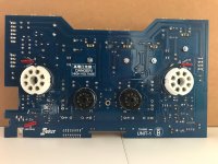
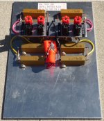
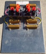
I recently made some stereo TDA7293 boards and am now working on a Rev.B because I realise, in hindsight, that my grounding topology is not particularly great (this is unrelated to my previous post about hum). One constraint I face in particular is that, for reasons of space and packaging, I need to build multi-channel (at least 2ch) boards and I have no more than 50mm of PCB width available for each channel. Most of the small-signal stuff is SMD, so that helps a little.

One major problem I have is no means to measure distortion with any accuracy so I am somewhat working in the dark with respect to trying different topologies that I've seen people recommend. A couple of features in particular I have seen on other power amp boards are:
  1. separate supplies including separate ground and separate decoupling caps for the input stages
  2. running the input-stage ground (SGND) back to the PSU star separately from power ground (PGND) on the PCB
  3. running the speaker return back to reservoir/star GND instead of to the PCB PGND
  4. running separate PGND lines for each channel, from the reservoirs to the output-stage decoupling centres
Some larger kits amps I've built do item 1, particularly with a very separate higher-voltage regulated supply to the differential and VAS, supplied and decoupled quite independently of the output stages. That design (from Silicon Chip I think) has 6 power connections: PGND, VCC_POWER, VEE_POWER, SGND, VCC_SIGNAL, VEE_SIGNAL. The two grounds are quite distinct, and there are decoupling caps obviously in both power systems.

An example of items 2 and 3 is in this LM3886 design, where there are separate PGND and SGND cables to each channel PCB. Implicitly also item 4 because it uses a separate board for each channel.

However, no commercial amp kits I've built - nor appnote PCB layouts - seem to take the approach of items 2, 3 or (where stereo) 4. Just one PGND from the reservoirs to an amp PCB, and the speaker return also goes via the PCB which ensures that the loop area in the output is minimised.

Further wrinkles:
  • The TDA7293 has four power pins, one pair for the input/driver stage, and one pair for the output stage.
  • I am slightly puzzled about decoupling in that LM3886 link above, wherein there are no decoupling caps attached to SGND
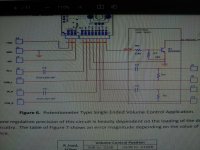
I presume for the LM3886, because it has only single VCC and VEE pins, it is not possible to have a separate/regulated input supply. And if a decoupling cap were introduced on the board between VCC and SGND, all you're going to achieve is making SGND noisy. So SGND is not really a power-supply (it should probably carry no DC current other than offset current from the non-inverting input), but is only a small-signal voltage reference.

With a TDA7293, it should be possible because there are separate supply pins on the chip... but I have not seen any published/tested designs that utilise the separate power pins in this way. Everyone, including the appnote, seem to just tie them together with a bit of copper. The appnote does have its "high efficiency" design but that's just Class G; at high power levels, the same half-wave noise on PWVs will appear on Vs.

I was considering putting a diode from PWVs to Vs and a decent decoupling cap on Vs (to where?!), on the principle that that should hold up Vs through any ripple on PWVs. But I don't know how to size the cap without knowing the current draw on Vs pins, and am concerned that I will just make it worse because the current through that diode might get mighty discontinuous - I would be trading some probably irrelevant third harmonics for much higher harmonics on the Vs pins, at some reduced level, and for which I have no idea of the PSRR at either frequency. As above, I do not have the equipment to do an A/B comparison. I don't really have the space to do a whole separate PSU for the input stages either, which would avoid that problem.

The reference design does not use hum-break resistors, and doesn't say what the SGND pin actually does. Should it be a stable local voltage reference? Should it align with the local system ground, or should it follow the virtual ground in the feedback network? What should the relationship between SGND and HBR be?

In terms of the speaker returns, I can see the benefit of not having a small copy of your output signal appear in PGND due to wire impedance, doubly so in terms of cross-talk on a multi-channel PCB. However, does it really matter if that noise on PGND is present if the whole amplifier feedback loop and ground reference are independent of PGND due to a separate SGND run? Yes there's direct cross-talk in the outputs from the shared PGND cable (200mm of 2.5mm^2 => 1.4mR => -75dB into 8R?) but that should be about it?

Therefore, I have a whole bunch of questions:
  1. Has anyone tried a separate regulated supply for +Vs/-Vs on a TDA7293? How much current is required?
  2. If you implemented such a regulated supply, would you decouple VS (pins 7&8) to SGND (pin 4) or to PGND?
  3. If I use a hum-break resistor, to which side of it is pin 4 (SGND on the chip) connected?
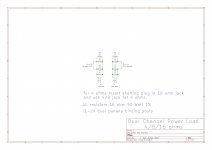
  4. If I run separate SGND and PGND cables to each board, is there any benefit to duplicating the PGND cables into one per channel, or running the speaker returns back directly to the star instead of via the PCB? Presumably there is no benefit to both splitting PGND intl LGND and RGND wires, and having the speaker returns not visit the board?
  5. Am I just chasing effects down below -90dB and should just stop worrying and be happy? 🙂
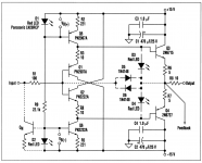
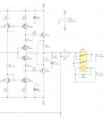
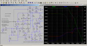
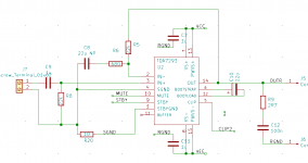
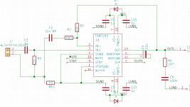
I've attached a couple of variants of schematics:
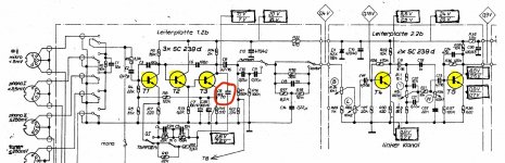
  • 7293-a shows a single power supply (probably OK), no decoupling to SGND (correct I think), and with SGND/pin4 on the input side of the hum-break resistor (who knows; probably wrong?)
  • 7293-b shows a split power supply using diodes (not sure), decoupled to SGND instead of PGND (probably wrong because of the diode, but maybe right if the Vs supplies were completely independent of the PWVs supplies) and with SGND/pin4 to actual SGND, with only the negative feedback path being on the input side of the HBR (who knows; probably right?).
Not shown on either are 1000uF/rail between VCC/GND/VEE, plus bleeders and fuses, plus a bunch of MUTE/STBY control logic referenced to SGND because it should be basically DC when playing.

You opinions please on the various combinations of options? Especially if you have any experience with interesting power-supply topologies for the TDA7293 and its behaviours.

thanks...

Attachments

  • 7293-a.png
    7293-a.png
    6.7 KB · Views: 150
  • 7293-b.png
    7293-b.png
    8.2 KB · Views: 145

Why is the tweeter above the midrange/ woofer?

Looking at Stereophile's vertical dispersion graphs, there is almost always a large suckout when listening above the tweeter's axis. I guess because of some interference from the midrange driver below it. They recommend putting the speaker on high stands and listening below the tweeter's axis. But I don't want high stands and what if I am listening standing up?

So why don't more speakers have the woofer on top like some Denon / Mission loudspeakers?

Happy Thanksgiving

finishing idea's for veneered plywood

I'm making a modular flexy rack with this ply. I used medium walnut Danish oil by Watco on one upper finished section in this same light plywood. it didn't take so great, it went blotchy for some reason.

Every other time the Danish oil worked superb for me, looks great. I want something easy to apply. Another reason I like the Danish oil, its usually easy to work with.

Attachments

  • 20220130_213012.jpg
    20220130_213012.jpg
    164.8 KB · Views: 145

Changing BJTs and Bias

Working on a 4ch Kenwood car amplifier with one pair of Sanken 2sa1303 and 2sc3284 BJTs per channel. But, Replacements don't appear to be available at the moment. I have MJL1302 and MJL3281s and they appear to be similar devices.
So, I tried replacing 1 pair. Upon trying to power up the amplifier with my current limited power supply. It appears to hit an 8a limit and then back to 0 repeatedly. I've tried the idle current adjustments as low as possible with the same outcome.
Is it possible that only replacing one pair is the cause and the amp has some sort of circuit that compares left and right? Or, Is it possible that the idle current doesn't have enough adjustment? Or, Are they just not going to work in this amplifier?
The amplifier works with the original BJTs. But, It does have DC offset. The amplifier draws 1.6A at idle and with all 4 idle current adjustments at their highest it only draws 1.8A. So, I'm assuming it's a very narrow adjustment.

Arcam Alpha 8R relays

A couple of years back the Left hand channel kept cutting out and on advice changed the source selector. This worked until recently but the problem has returned. It only cuts in when I crank the volume up to max (painful!), and a post I saw somewhere on the net suggested that the problem was with the (mute) relay.
It makes sense to me that changing the input selector made for a stronger signal which wouldn't cut out, but it seems that the relay becomes less efficient with arcing, and has to be cleaned / changed.
I've opened the unit but has no idea what the relay unit looks like, how to get at it, and how to burnish the contacts.
Any ideas (before I have to junk it)?
Cheers.

Output Transformer Winding.

When winding OP-transformers, keeping parasitic inductance and stray capacitance at low values is a good thing.
If there's room to spare inside the lamination window, adding extra layers of insulation would help lessen stray capacitance between layers.
-Would this also result in less coupling between primary and secondary layers, thereby increasing parasitic inductance?

Next question: -Will adding copper foil (electrostatic shielding) between layers decrease stray capacitance?

Transformer design is very much like the ocean, giving with one hand and taking away with the other.

Denon poa-4400 is a Threshold project?

Hi Nelson

I have found on the internet the following statement :

DENON's Reference-Class POA-4400 & 6600 monaural power amps
that have earned high marks from audiophiles and critics
throughout the world. This affordable yet luxurious
monaural power amps with its Dual Super NON-NFB circuit
(The Nelson Pass 'Stasis' design, and were built under
licence from Threshold) delivers high power while
preserving even the most delicate nuances of high-quality
digital sound sources."

Is this true?

Thanks for your attention

Best Regards from Italy

Vittorio Gasparotto

Repositioning Maggie MGIIIa's after many changes (long)

My system has had a series of alterations over the past few years that seem to have made some substantial cumulative changes. Now I seem to need some help retweaking it. Let me say at the outset, I'd like to avoid another "digital-now-is-so-much-better" or "such-and-such-is-mismatched" conversation about buying new stuff. Please work with me here and resist recommending some new gear (or a new house!) as the fix. So, that said, here's the story.

Equipment and setup

Speakers are MGIIIa's per post title. Yes, very old. However, they were rebuilt by Magnepan about 6 years ago - new membrane, wires, ribbons, socks and some other unspecified changes. They are now as new. At the time Magnepan said that all this made them the equal of the MG 3.7's. Maybe even better in the low end. I don't know, except that they were certainly improved greatly. The listening area is shown below and pretty much to scale. Although the room itself is large there's limited flexibility in changing it too dramatically. The door on the right side puts the home theater setup on the left side (which, incidentally, uses Maggie MMG's and a MMG C). Reversing the speakers and chair would put the back of the right speaker partially blocking the hallway. So, I'm kind of stuck with moving the speakers around the general region that they're in. The blue circles are tube traps, and they could be moved easily. The ones behind the TV are 16"x36" and do sonically improve matters on that end. The ones on the right are stacked 9"x37" + 11"x37" units. Their placement may or may not make sense, that's just where they fit best physically with best WAF.

The source is a Lumin U1 Mini feeding a Sonic Frontiers SFD-2 MkIII via BNC coax. It can also be routed through the Assemblage D2D-1 via AES/SBU. I'm not yet sure which I like better. The SFD-2 was further upgraded a few years ago by Parts Connexion (ex SF) and is tip top. This feeds a Krell KBL. The KBL's power supply was recapped and fixed a few years ago. A month or so ago the preamp itself was completely recapped during another repair in which a few transistors in the phase splitter were replaced . I mention this cause the KBL fixes did seem to have a significant effect on the sonics. More on that later. All this feeds a recapped ML No. 332. Though old, overall the system is in excellent shape electronically and sonically - extremely resolving, revealing, holographic and impactful. It's not clinical or harsh in any way, it just draws you in and raises the hair on your neck. I think I'd have to spend a LOT more $$$ to make a meaningful improvement, though more likely not, no real improvement just some kind of small difference.

listening[506].JPG


What's the problem?

Basically the bass was improved. Too much in fact. After the Maggie rebuild the system was substantially deeper and better controlled. The recent switch from the Node 2i to the Lumin greatly improved system detail and resolution in general. But the KBL rebuild seemed to have the most profound effect. It seems like the bass suddenly went an octave lower. It's also tighter and incredibly impactful. I suspect that the KBL now sounds like it did when it was new but the decay was so slow that it wasn't noticable. It's like the bass tone control got turned up, except there isn't one. Or, maybe, I've gotten used to less bass and now I'm just getting what I should have had all along? There's certainly a sense of hearing new stuff that I never heard before (we've all had that feeling at times, I'm sure).

So, what I want to do is fish for some ideas on how to tame the bass a little. I can rearrange the tube traps up to a point. Obviously the system is closed on one side and open on the other. I don't know what effect that might have. I've started moving the speakers around a little but any informed advice would be great. It wouldn't be too hard to slide the system to the left a foot or 2 if that would help. I'd also consider another tube trap or 2, but which ones and where would they go? Looking forward to ideas and lively discussion. Thanks and cheers,

Video of Richard Heyser's first public TDS demo

Kudos to the folks at SynAudCon for recently making this video available to the public. And to its founder Don Davis for making it in the first place in 1979. Don was the sole voice promoting and teaching Richard Heyser's Time Delay Spectrometry, which had lain dormant for 10 years after it was introduced.

https://www.prosoundtraining.com/2021/02/04/heyser-videos/
Many folks are unaware of Dick's genius, and his huge influence on measurement and evaluation of loudspeakers and acoustics. I consider his AES papers essential reading. But there is no better way to get a feel for the man than to watch this video.

This was Dick's first public presentation of TDS, using surplus equipment that he modified, and some he built himself. The FFT analyzers used were loaners. A couple bugs had not yet been worked out of the system. As a result, the presentation bogs down in a couple of places while they're being tracked down. It might have been better if they just edited those out. I attended his first formal TDS class in 1981, and it all went much smoother.

Enjoy.

help diagnose power amp buzzing from one channel

This intermittent buzzing comes and goes at random. I may catch it for 5 or 10 seconds once in a month, or as often as every hour or two for the entire length of my listening session. It starts then stops and all seems well. The amp sounds ok otherwise.

A few of the symptoms are as follows...

Right channel only
Does not get louder when volume is increased. Its not even noticeable when the volume is up. I can't even tell its occurring until I decrease the volume or catch it between tracks.

It stops and starts at random. Its happening more frequently today, still very sporadically. Yesterday during my listen I never heard it once.

I'm hoping its something simple, like a loose ground or inferior cap inside. I can't afford to pay a tech and will be system less if I'm not able to track down myself. I'm not sure if I'm pushing my luck by using the amp before it can be resolved. Hopfully more damage doesn't result. I can't afford to replace a 4k amp right now. I can't even afford to pay a tech to look at it.

I was hoping someone could possibly offer some kind of check list that might help me narrow it down?

Thanks in advance.

Piezo Buffer Upright Bass

Hi all, I'm using The Realist Copperhead piezo pickup on my upright bass. I'm noticing the output seems to lack low frequencies. I discovered that this pickup requires its output be sent to an amp with 10Mohm input impedance. Most mainstream amps including mine are 1Mohm. Others in the community have reported impedance mismatch can produce this symptom.

I am looking to build this piezo buffer circuit. The designer has advised me: 'The usual input impedance of my circuit is about 4.8Mohm. It would be possible to increase the value of the 4.7M and 10M resistors if you need higher - mostly they are there to bleed off any DC offset.'
From this, I have determined I need to change the resistors marked below.

I'm hoping anyone here can tell me what resistor values I should use for R1, R2, R3 for an input impedance of 10Mohm.

1643091627206.png

Rockford Fosgate Punch P1000X4D

Has anyone seen one of these?

This amp is using 7-legged devices in the PS, though legs 2,3, 5, 6,7 are all tied together on the PCB. I have not seen FETs like this before if they are even fets.

The amp only briefly powers for 1/4 second and displays amber LEDs on the pre-amp board. I believe that is in protection but not fully sure.

There is PS drive on the gates of these strange fets for the brief moment. Nothin shorted in the amp. I was thinking maybe removing the main rectifiers to see if the PS side will fully power up.

Otherwise I guess I'll ask; is there a schematic for this amp by chance?


The amp seems to not be making proper negative rail voltage at D21, and D22. I'm 95% sure both of these rectifiers are duds.

Threshold SA/1 hiss

Hi everybody,

1st post. Unfortunatly I do not have the technical know how of many people here, but I much appreciate the input on my problem.

I just had the SA/1s recapped and looked over by a well respected tech in the industry. Amps came back and sound great, but they have a hissing problem.

power caps were replaced with 47000 Epcos 100v

Amps were previously modded with power filtering.

4BE564AB-31EB-48DB-A248-EF2537903465.jpeg


Issue:

Power on, no RCA input connected = no hiss, dead quiet.
As soon as I connect RCA from various sources and different cables I am getting a hiss in both speakers. Tried from preamp, directly from 2 DACs and each one provides hiss. All upstream components have been used with other amps and there was no issue.

What have we tried:
1) Disconnect small yellow parallel caps ( value of the caps and brand unknown as they were installed years ago)
2) tried grounding the RCA input to star
3) move pcb ground away from power filter in the back.

no impact on hiss.

These amps sound spectacular even compared to my modern amps. Without the hiss I would be in sonic heaven. I would appreciate any input you can provide.

Attachments

  • 72AFC056-6B8B-488B-B6C4-D66FF94FFBF9.png
    72AFC056-6B8B-488B-B6C4-D66FF94FFBF9.png
    460.4 KB · Views: 164

FS: Audio Amp Power Output Devices

I have several audio power output device pairs for sale. These are all NOS (New Old Stock). They are guaranteed not to be fakes.
I bought them direct from the OEM. These days I am moving to Class 'D'. My change of heart is your gain.

10 devices - NJW3281G (NPN) / 40 devices - MJW1302G (PNP) $100 (Plus cost to ship)

45 devices - MJL21194G (NPN) / 45 devices - MJL21193G (PNP) $350 (Plus cost to ship)

50 devices - MJL4281A (NPN) / 70 devices - MJL4302A (PNP) $500 (Plus cost to ship)

24 devices - 2SA1987 (PNP) / 24 devices - 2SC5359 (NPN) $100 (Plus cost to ship)

Please message me if you are interested in any of the above.

Planet 10 - Classic GR Mar-Ken12 p vs. 12.2p Small Reflex

Liebe DIY-Gemeinde, liebe MarkAudio-Spezialisten – gibt es hier im Forum jemanden, der eine fundierte Aussage über die Stimmfrequenz des Classic GR Mar-Ken12p beim Vergleich zu dem des Alpair 12.2p Small Reflex (abgestimmt auf 55 Hz) machen kann, zB wie tief kann der MA 12P /P12.2 in diesem Gehäuse (Classic GR Mar-Ken12p) im LF-Bereich gehen?


Mit freundlichen Grüßen Stefan

Decoupling & Bi-passing capacitors - Muses Elect V/C

Hi. Sorry if this is a ''Nob question''. I am trying to upgrade my current V/C on pre amp to Audio Academy Muses V/C with remote.

On the installation it calls for a 47 to 100uF DC blocking cap to be used at the input. then added to these caps need a Bi-passing cap ''10nF to 100nF film or C0G (NP0) ceramic''

''Use direct input connection only when it is assured that no DC voltage will be applied to the inputs. Use direct output connection only when no DC voltage will be applied to the inputs AND outputs of the chip. In all other cases high quality DC blocking capacitors shall be used. High quality polypropylene capacitors present the best choice for the output DC blocking when the control is feeding high impedance loads. They get pricey at higher than 10uF values. High quality non-polar electrolytic capacitors of 47uf to 100uF provide good results when bypassed with 10nF to 100nF film or C0G (NP0) ceramic capacitors.''


How do you do that,
  • does the bi-pass capacitor bridge over the blocking capacitor,
  • or does it does it go from the blocking capacitors output to ground?

Have attached the wiring diagram shown on the web site

Cheers for any help

Attachments

  • Muses wiring.jpg
    Muses wiring.jpg
    1.2 MB · Views: 137

Tweeters with Low crossover frequency

Hi,

I just came across this tweeter. What caught my eye was a Fs of 425Hz!!! Looking at the frequency response, I noticed, the freq response is pretty much flat until 500Hz.

http://www.scan-speak.dk/datasheet/pdf/d3004-602010.pdf

I was wondering what your opinion would be about running this speaker crossed really low, say about 700Hz.

There are other tweeters with these specifications

TW030WA05 to 08

I would like to see you opinions on how you think these class of tweeters will perform if used to run with a crossover frequency of 700Hz.

Oon

  • Locked
For Sale Elekit TU-8500 Pre-Amplifier

Hi I am selling my Elekit TU-8500 Pre-Amplifier with GE 5965A and Amtrans upgrade resistors. Nicely completed unit in excellent working condition. Selling price is CADS$250 + shipping. Less than 5 hours of use on it. Located in Canada. SOLD SOLD

Attachments

  • IMG_2677.jpg
    IMG_2677.jpg
    414 KB · Views: 187
  • IMG_2678.jpg
    IMG_2678.jpg
    308.2 KB · Views: 208
  • IMG_2679.jpg
    IMG_2679.jpg
    428.8 KB · Views: 198

first attempt at a Salamander

I assemble tomorrow..

4 shelf system
22"x22" x 3/4" plywood
1/2" threaded rod with poly lock thread
Veneer species unknown, white Maple?

I have some stainless steel I might use to dress up corners. And add a whole lot more strength. Its tough to cut without a water jet. I only have a zip wheel.

Attachments

  • 20220130_213012.jpg
    20220130_213012.jpg
    164.8 KB · Views: 130
  • 20220201_191055.jpg
    20220201_191055.jpg
    338.8 KB · Views: 136
  • 20220130_173545.jpg
    20220130_173545.jpg
    232.8 KB · Views: 125
Projects by fanatics, for fanatics
Get answers and advice for everyone wanting to learn the art of audio.
Join the Community
507,758
Members
7,887,198
Messages

Filter

Forum Statistics

Threads
406,170
Messages
7,887,198
Members
507,758
Latest member
Cindy