Why would anyone disable an amp's balance control?

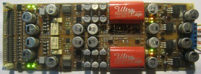
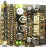
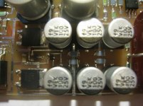
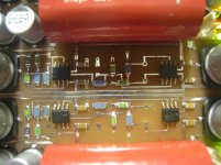
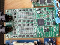
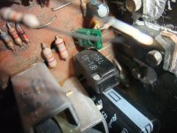
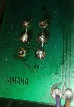
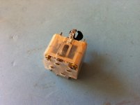
I bought a Yamaha CA-2010 integrated amplifier from 1977 with a balance control which doesn't work. Opening the device, the problem is immediately apparent: a technician has disabled balance control. See picture.

Why would such a thing be necessary? I am asking here before I restore it to stock condition.

Attachments

  • IMG_20210527_023541.jpg
    IMG_20210527_023541.jpg
    506.2 KB · Views: 432

Refurbishment of my Yamaha NS-1000Ms

I have started to work on an extensive refurbishment of my Yamaha NS-1000M speakers and a friend suggested that forum members may be interested. The work is in progress and I am taking lots of pictures of each stage. I've already done a lot of planing but the actual physical work has only just begun.

The pictures and all details can be found here:

http://www.audioflat.co.uk/phpBB3/viewtopic.php?f=7&t=159

I've already made some speaker stands for the Yamaha's and anti-diffraction rings for the mid and tweeter.

I intend to make the crossovers external and upgrade them, laminate the cabinets in gloss black, replace the L-pads with fixed resistors and fill the cabinet holes, re-make the back connection panels, re-wire them and address a few other minor issues (make new badges, gaskets etc.).

200W amplifier design

Hi all!

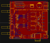
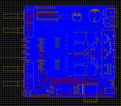
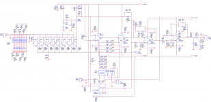
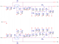
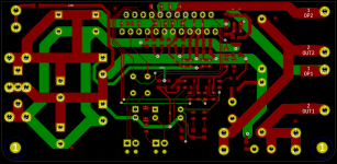
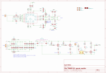
I have designed a 200W HiFi audio amplifier based on the TPA3116. I am trying to make it sound amazing ( 😄 doesn't everyone), so I want to know if anyone has any feed back on design, or things I should add / change.

Schematic, PCB top and bottom, and 3D photos attached.

Thanks in advance for any feedback!

Attachments

  • Screen Shot 2022-01-27 at 10.31.43 AM.png
    Screen Shot 2022-01-27 at 10.31.43 AM.png
    54.6 KB · Views: 231
  • Screen Shot 2022-01-27 at 10.31.54 AM.png
    Screen Shot 2022-01-27 at 10.31.54 AM.png
    46.1 KB · Views: 177
  • Screen Shot 2022-01-27 at 10.32.08 AM.png
    Screen Shot 2022-01-27 at 10.32.08 AM.png
    116.6 KB · Views: 229
  • Schematic_100W Bluetooth Speaker_2022-01-27.png
    Schematic_100W Bluetooth Speaker_2022-01-27.png
    98.9 KB · Views: 239

Luxman r-113

I don't get audio playback from any component jacks except the CD and that only when the straight is engaged. I have the schematic and have some knowledge as to reading it, but there is this broken line that goes to multiple locations on the board. I don't know what this line is supposed to represent. Its in the subsonic filter/cd straight part of the schematic which I have attached. Any advice on this issue and opinion on the problem component would be appreciated. Not sure if I only attached the page or the complete manual, if so reference is page 11. Thanks

Attachments

15" coax drivers for stage wedges

I'm looking to make a batch of stage wedges primary concerns:
1) Output
2) Fidelity
3) Driver cost (disqualifies things like the BMS triax)
4) Driver durability (3" coil or more ideal)

So far the B&C 15fhx76 seems to be a good comprimise: 15FHX76 Coaxials - B&C Speakers

I am quite attacted to the drivers that use a seperate horn to the cone for more narrow coverage and to avoid the cone modulating the HF. I could be wrong about a 60x40 coverage been desirable for a wedge though? Non of the 15" coax drivers I have seen are especialy Hi-Fi with frequency response annomlies around the crossover frequency right in the midband of human hearing. The wedges will be activly processed.

Hawk A19 - Higher power version

As some of you know I have experimented with teh Hawk A19 amplifier to power my Orions. The sound is absolutely stunning but with higher volumes I can hear that the amplifiers for the bass are clipping.
So back to the drawingboard.
The bottleneck is the stabilizer for the DC regulation being a uA7x12. I have now designed a stabilizer that can handle ~60V so I can move from 25V to ~50V rails giving me the power required.
There are a number of members that have bought my PCB's and as soon as I have tested all aspects of the new configuration I'm offering a new PCB at reduced price.
I will publish more details as they become available.

Question about the separate power supply of the AD1865

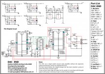
Hi, I'm building a dac with AD1865 (a clone of the note audio), with the cs8414 receiver, both chips have both analog and digital power, and I was wondering: how useful would it be to separate the power supplies of the two chips? Making an analog and digital power supply for the dac, and one also for the receiver, so as to have a total of 4 power supplies, 2 each chip. All power supplies are further filtered with the tl431. Like this scheme.

Tiziano

Attachments

  • DAC-END-cricuit.jpg
    DAC-END-cricuit.jpg
    338.1 KB · Views: 583

Parasound HCA-2200II Upgrade

Our audio shop has closed due to retirement and I would like to share our mod for the HCA-2200II. The only person we have ever shared this with was John Curl many years ago. I hope that this will help some of you who would like a little better sound quality but the mod will improve clarity first and foremost.

Attachments

2Sk100 , 2SK170-V, Yamaha C4

Hello,
I need to replace a 2SK100. A pair reside in a Yamaha C4 preamp and one appears to be playing up.
It’s a ‘dual jfet’ and one suggestion has been to thermally couple a well-matched pair of 2SK170-V.
Any advice gratefully accepted with regards to the suitability of this solution, better alternatives or, indeed, where best to try and procure genuine stock of 2SK170-V.
Many thanks.

Crossfire C5-1700D

Working on this Type 3 board.

-Has +-16vDC regulated, and +-105vDC rail.
-No DC on speaker terminals.
-Relays release during power up.
-Idles at 1.9A, but at HIGH input signal pulls about 5A.
-I can observe the square wave oscillation at speaker terminals
-No DC on audio pins of any main opamp
-No protection led
-No failed PS nor output FET.
-Output driver board is like the one attached.
-There is barely any audio at speaker terminals. To me what little audio there is, seems like the amplifier is still muted.

Why would this amp not be passing audio to speaker terminals?

Attachments

  • DSCN0036b.jpg
    DSCN0036b.jpg
    115.3 KB · Views: 105

USB to I2S for the 3e audio DSP board?

Hi there,

I recently found the 3e audio DSP board and its very suitable for my needs, but I wanna go a step further to use the I2S input rather than the RCA in. I am a bit new to these things so I spoke to 3e audio, they said their DSP board only takes slave input. I am confused, I searched for USB to I2S board products (like on Aliexpress), there are tons but I dont really see them mentioning Master/Slave mode about their board. I dont know what product I could use, could anybody give me some help and point me to a USB to I2S product that could work with the 3e audio DSP board? Thanks a lot!

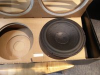
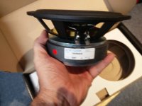
For Sale One (1) ScanSpeak 18W/8545-00 MidWoofer (used) for sale

FS: One ScanSpeak 18W/8545-00 Midwoofer paper cone (used) for sale. Hi, this woofer was removed from a working Verity Audio speaker. I replaced the pair of woofers because one was defective, and the other was not. This is your chance to get a great woofer, just need to buy an other one and you are set to build a great speaker. Cost for a new one is 255$CAN + tx (or 200U$). Selling for 100U$ + shipping

Driver is in perfect condition. I can send also the defective one if you want to try to repair it. Shipping box will be heavier, and shipping cost a little higher in consequence.

Btw the only difference according to Solen between the 18W/8545-00 and the new 18W/8545-01 is the basket material, stiffer with the newer -01, both drivers are veritually inditical.

I can use the original ScanSpeak box for safe shipping. The box shown is for the two woofers that I bought, hence the difference in part number.

Thanks for looking

Attachments

  • IMG_20220107_104215.jpg
    IMG_20220107_104215.jpg
    331.5 KB · Views: 207
  • IMG_20220107_104330.jpg
    IMG_20220107_104330.jpg
    155.2 KB · Views: 210
  • IMG_20220107_104349.jpg
    IMG_20220107_104349.jpg
    114.8 KB · Views: 225

For Sale Headphone Amplifier Housings on tubes

Sale of cases of amplifiers for headphones on two tubes.
The case is made of steel, painted with powder paint. The housing includes:
  • chassis
  • bottom cover
  • two caps for output transformers
  • one cap for a power transformer

SW51_DIY_1.jpg


Appearance on the chassis in front. The purpose of the hole from left to right:
  • Two holes for 1.4 jack
  • Hole for ALPS RK27
  • Hole for CARLING toggle switch
  • Hole for LED

SW51_DIY_F.jpg


Rear view of the chassis. The purpose of the holes:
  • Two holes for RCA
  • Hole for AC connector in fuse
  • Hole for power switch

SW51_DIY_B.jpg


Dimensional drawing of the chassis:

1644259696830.png


The case can be used to build a transformer amplifier for headphones on two tubes. For example, like these amplifiers

1644259750054.png


Case cost $50 + shipping
Shipping from Moscow, Russia
There are 16 cases

Measuring TSE-II Filament currents?

Hi All,

I am trying to determine if a new transformer I purchased from Edcor is faulty, as it's buzzing a lot. I am trying to measure the current draw on all the taps while the amp is in operation. At someone's suggestion here I was able to measure the HV Tap my measuring the voltage drop across the choke.

Is there anything similar I can do for two filament currents? Based on the schematic I am not quite sure where I could measure a voltage drop (or DC voltage through the meter).

Thanks!

For Sale Genalex Gold Lion 300B, 12AU7, 12AX7

SOLD

This is a set of tubes that I bought for an Elekit TU-8600 amplifier. They have been used for probably less than 50hrs. These are great tubes, I just got the bug to upgrade so no longer have a use for them. They are the current production models and cost about $450 new. The set includes:

2 - Gold Lion Genalex ECC82 / 12AU7

1 - Gold Lion Genalex ECC83 / 12AX7

2 - Gold Lion Genalex 300B

Please let me know if you have any questions. Shipping within CONUS only. Buyer to cover shipping and PayPal fees.
3.jpg
2.jpg
1.jpg

speaker with two full range drivers

This may be a dumb idea, but being a newbie I will ask. Is there any merit to making a speaker with two identical full range drivers? I know the arrays are always matched to keep the same impedance and two drivers will cut the impedance by half. Will it help sound stage, separation, etc..... I am trying to build something here with some $$$ constraints and this is an off the cuff idea. Thanks for your replies in advance.
Salsero

crowhurst twin coupled amp with dissimilar output transformers

I've been wondering for a long time, if one had two sets of transformers that were not quite the same, say one set 4K to 8Ω, and one 2K to 8Ω, would the twin coupled output stage function with using the 4K in the plate side, and the 2K in the cathode side of the circuit, or vice versa? or do the transformers need to be identical type in order for the circuit to function properly?

I'm not sure why one might want to do this, other than not having a set of 4 output transformers, but perhaps there's benefit to it in some situations?

Resolved - Implemented Seeing Stars

As @tombo56 mentioned, making more donations of different types gives one ahem stars. I was happy to make donations in return for shipping on a couple of items recently, but I certainly don't rank as a 3-star anything (well, perhaps a burro). I'm happy with the good vibes that generally pervade diyAudio, and any potential karma that may ensue.

Could some/all of those be removed without jeopardizing my ad-free nirvana?

Kind regards,
Drew

Open baffle for half critical listening half home theater setup?

Right now in my TV room I have a pair of Snell E/IIIs and a cheap Pioneer receiver. I don't really like the sound but we mainly watch TV on it so it doesn't bother me. I would like to start listening to more music in this room though. It's probably about 18x12' with what I'm guessing are 11-12' ceilings... floor to ceiling windows and hardwood floors (big L couch and rug though). TV/speakers are on a narrow wall.

I have DML panels in my kitchen which is my "main" listening room for now, and I also have some narrow field monitors. Between the two I prefer and have become accustomed to the open soundstage of the DMLs. I don't think I want to do another set of DMLs for the TV room, but I'm not completely opposed.

I guess my main questions are what considerations should I make in choosing drivers for this use. I would say my goals for it are:
  • Wider soundstage
  • Similar low end extension (~40Hz)
  • High efficiency (I would like to use my ZOUDIO as the amp)
I am thinking about some GRS Planars to run down to maybe 800-1000Hz and one of the many OB friendly 12s. I feel like with the narrow room, all the reflections and good XO setup (I will run active) beaming from the woofer shouldn't be an issue. I am also redoing the setup in the kitchen so I could repurpose a pair of the DMLs coupled with a bass driver. I don't want to run a center or rear channels and this is a low dB setup- we mainly watch TV when kids are sleeping and I don't like to listen to music super loud these days. Just looking for insight/advice on such a setup; I feel like it's very common.

Hps 5.1

And here's probably the last in the HPS series.

HPS 5.1 is built on the same foundation as HPS 5.0, using the same SMD technology (which, by the way, I find much easier to work and rework compared to through hole; the flip side is the rather high cost of good quality 1206 SMD passive components).

There are though some significant improvements. The head amp follows the same simple architecture, an ultra low noise transconductance stage, followed by a high gain transimpedance stage and a servo, to allow DC coupling to the output. The LF open loop gain is still gm*R203 (see HPS51.png), where gm is the tranconductance stage gain, approximately 2*Id/Vt, where Id is the total JFETs drain current (~90mA) and Vt is the BF862 pinch voltage (~0.8V). However, the low noise stage is now cascoded using a low noise ZXT690 power device. The JFETs Vds is about 3V. At this voltage, BF862 does not have any hot carrier injection noise. The cascode reference (~3.6V) is provided by two LEDs, decoupled for low noise by a large electrolytic.

To greatly improve the input stage PSRR, two changes were made. First, the lead-lag compensation network R206/C206 is now connected to the positive supply rather than to the ground. At the same time, the non inverting input of the transimpedance stage opamp is now decoupled to the same positive supply by C227. The net effect is that, for a rather large frequency range certainly well below and over the audio range), the AC voltage gain of the transimpedance stage is very low; any noise or other perturbations appear as common mode for the opamp, and therefore they are rejected. A PSRR of ~-50dB is obtained.

This, coupled with the same noise cancelling power buffer (using a Sziklay current feedback series regulator, that greatly reduces the equivalent Rbb of the power device, see HPS51-PS.png) leads an overall PSRR performance comparable to HPS 3.1 and HPS 4.2, but with a much simpler solution.

This is obvious when looking at the noise performance (see HPS51-noise.png). While HPS 5.0 had the 60Hz harmonic noise rather on the high side, HPS 5.1 has not more than 8nV equivalent input 60Hz noise, which is excellent. The 60Hz harmonic noise is actually not injected from the power supply, but from the magnetic coupling with the environment. The overall noise is around 0.3nV/rtHz and the corner frequency is typical for JFETs, some 300Hz.

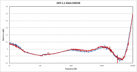
The RIAA stages are identical with HPS 5.0, and so is the power supply. The measured RIAA precision is attached, it is under 0.1dB to well over the audio range, see RIAA.png below. The opamps are the National LME49870, supporting +/-22V. As usual, the Neumann pole is implemented. I chosed to avoid implementing a high pass 20Hz rumble filter in the preamp, this can be externally attached at the output.

The head amp gain is switchable via a NEC low signal relay (one of the best I was able to find, actually slightly beats the Panasonic devices) for a total of 60dB (MC) and 48dB (MM). Switching the head amp gain actually preserves the dynamic range of 32dB when switching to MM.

As I said, this is probably the last RIAA pre that I am building. In a sense, the circle is now closed. I started from the Colins pre (HPS 1.0), improved the Colins architecture (HPS 2.0), developed a supersymmetrical complementary JFET head amp architecture for the ultimate performance (HPS 3.1), then I designed and built a series of ultra low noise bipolar preamps, having virtually zero adjustable input bias current (so all DC coupling to the output was possible) as first HPS 4.1 (using Jung regulators and local buffers) and then HPS 4.2 (using TMC compensated local shunt regulators). Finally, I have succesfully tried to greatly reduce the complexity without impacting the performance; HPS 5.1 has virtually the same (or even better in some respects) to HPS 3.1, and uses low noise JFETs in current production, selling for pennies. The power supply went from Jung regulators, to high performance shunt regulators, to ultra simple LM317/LM337 plus a noise cancelling power buffer.

Which one is the best? Time will tell, I like best the HPS 5.1. Secondly comes HPS 4.2 (the bipolar with shunt regulators) and finaly HPS 3.1. But then of course, I am biased, and didn't do any blind test to prove my preferences 😀.

Some pictures of the construction are below (HPS51.jpg, HPS51-IS the head amp detail, HPS51-PB.jpg the power buffer detail, HPS51-RIAA.jpg the RIAA stages). The Gerbers will be available for free on my web site, as soon as I'll find the time for an update.

EDIT: if anybody is wondering, HPS5.1 and HPS 5.0 are 100% hand soldered using a Weller fine tip and 0.5mm zero residue flux 63/37 solder.

Attachments

  • HPS51.png
    HPS51.png
    36.2 KB · Views: 4,042
  • HPS51-PS.png
    HPS51-PS.png
    15.8 KB · Views: 2,858
  • HPS51.jpg
    HPS51.jpg
    90.7 KB · Views: 2,777
  • HPS51-IS.jpg
    HPS51-IS.jpg
    127 KB · Views: 2,698
  • HPS51-PB.jpg
    HPS51-PB.jpg
    123 KB · Views: 2,604
  • HPS51-NOISE.png
    HPS51-NOISE.png
    7 KB · Views: 831
  • HPS51-RIAA.jpg
    HPS51-RIAA.jpg
    133.4 KB · Views: 914
  • RIAA.png
    RIAA.png
    40.3 KB · Views: 961

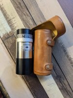
For Sale FS Brüel & Kjær Type 4230 Calibrator

For sale,

Brüel & Kjær 4230 Sound Level Calibrator, used but in absolute mint condition.
Last time when checked (couple of years ago) against another calibrator, still was well within spec.

datasheet:
https://www.technicalaudio.com/pdf/Bruel&Kjaer/Bruel&Kjaer_Calibrator_Sound_Level_4230.pdf
price: 175 euro exl shipping or send me a reasonable bid via PM

Attachments

  • B&K_1.jpeg
    B&K_1.jpeg
    264.4 KB · Views: 140
  • B&K_2.jpeg
    B&K_2.jpeg
    217.9 KB · Views: 131
  • B&K_3.jpeg
    B&K_3.jpeg
    429 KB · Views: 139

AKM replacement ideas

Hi guys,

I use the AKM AK4430 in a DIY DAC that I also sell as a finished product.

After the fire in Japan it is impossible to source this part. Do you know of a timeline for AKM rebooting production?

In the meantime I have asked brokers for component quotes. With the prices that I get it makes financial sense to redesign the entire product around a different DAC chip.

The AK4430 is convenient in that it charge pumps its own negative supply and provides a line driver output.

If I could dream up a DAC chip it would be one with those feature, improved SNR and added MQA decode. And of course good availability. Many people point to ESS but they are only traded by brokers, not on Mouser/DigiKey/RS etc.


Thanks,
Børge

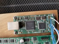
Soekris DAC damaged by static

good day diy audio

i have been happily using the soekris dac (dam 1021) for a few years now

*see attached pics

unfortunately, yesterday, a static discharge ( walked across the carpet and touched the metal volume knob) caused an audible pop,
and now i cant get any sound through the dac 🙁

when i replace the dac with another device, all works fine. so unfortunately it is the dac that was damaged

is this fixable?

any ideas where to start re troubleshooting?

much thx

sw

Attachments

  • 20220123_113616.jpg
    20220123_113616.jpg
    536.3 KB · Views: 226
  • 20220123_113627.jpg
    20220123_113627.jpg
    762 KB · Views: 265
  • 20220123_113631.jpg
    20220123_113631.jpg
    520.9 KB · Views: 226

HK730

Hello,

I recently bought locally a Harman Kardon 730 receiver from the 70's. It works flawlessly with the exception of one thing: When I power it down and there is an input to it (meaning into its Auxiliary input from a DAC or another device), it continues to play flawlessly for nine seconds and then it shuts down in another two, but the music is distorted throughout that last period. The volume at which music is played does not have effect on the times described above i.e. It could be very quiet or loud, it always shuts down in 11 seconds. Interesting to note is that If I set it to radio, the receiver shuts down as it should: it takes no more than two seconds. Also, the lamps on the front turn off immediately, so in essence, the phenomenon is observed only when Auxiliary inputs are being used.

I intend to fix this in a month, during spring break and would appreciate if I get some suggestions with regards where and what to look for. I was going to check first for ways the large capacitors within the PS continue to discharge and power the preamp and amp sections. I have attached the service manual which contains all the schematics.

Thanks in advance.

Best

Soundork

Attachments

Understanding Spice Models

I am struggling to understand Spice model coding. I understand the first line sets the name and pin count...I think. +PARAMS: sets parameters to be used in calculations. In this example of a transformer, what do the numbers mean after RS1, LP1, RP1...etc? At first, I thought it might be pin numbers saying that this calculation happens between this and that pin. But then I see the numbers 12 and 45, which are not pin numbers. I have tried to find info on the subject, without success. I think I need a very elementary explanation. I'm just trying to figure out how to adjust this transformer to whatever my design calls for. For instance, a Blackface Bassman transformer with only a 4 ohm output, or a Marshall 100W transformer with 16-, 8-, and 4-ohm outputs. I am unsure why there are 9 pins needed in this example. It is an output transformer with 16-, 8-, and 4-ohm taps. I would think only 7 pins would be needed. I would really like to know more about the subject and be able to adjust the code properly, draw my own symbol in Multisim, and assign the pins.

It seems I also don't know how to add code properly here...?

[I].SUBCKT DYNA_OUTPUT_XFRMR 1 2 3 4 5 6 7 8 9 ; PARAMETERS FOR MARK 3: +PARAMS: LPRIM=60 LLKG=.040 RPRIM=125 CPRIM=1.04NF LRATIO={4/4300} * ERIC BARBOUR ARTICLE: ~233H TOTAL PRIMARY L FOR MARK 3. * MARK 3: LPRIM=60 LLKG=.040 RPRIM=125 CPRIM=1.04NF LRATIO={4/4300} * LPRIM IS THE TOTAL PRIMARY L (VARIES WITH MEASUREMENT). * LLKG IS THE LEAKAGE L (MEASURABLE: CONSISTENT). * RPRIM IS THE TOTAL PRIMARY R. * CPRIM IS THE MEASURED PRIMARY CAPACITANCE. * LRATIO IS THE INDUCTANCE RATIO: (4 OHMS)/(PRIMARY Z). .PARAM QFCTR={LPRIM/LLKG} ; Q-FACTOR. CS1 1 5 {CPRIM} ; PRIMARY CAPACITANCE RS1 1 5 300K ; SHUNT R FOR HIGH FREQUENCY EFFECTS. LP1 1 12 {LPRIM*.09} ; .7164H ; PRIMARY RP1 12 2 {RPRIM*.5} LP2 2 3 {LPRIM*.04} ; .3184H LP3 3 4 {LPRIM*.04} LP4 4 45 {LPRIM*.09} RP4 45 5 {RPRIM*.5} LP5 7 6 {.34315*LPRIM*LRATIO} ; 8-16 OHM WINDING: (2-SQRT(2))^2 LP6 8 7 {.17157*LPRIM*LRATIO} ; 4-8 OHM WINDING: (SQRT(2)-1)^2 LP7 9 8 {LPRIM*LRATIO} ; COM-4 OHM WINDING KALL LP1 LP2 LP3 LP4 LP5 LP6 LP7 {1-1/(2*QFCTR)} ; COUPLING .ENDS[/I]
  • Like
Reactions: anchorman

Flow question on PSU filter

I've read veterans here advising us non experts to think about circuit flow, avoiding sharp corners, and maximising reference to circuit ground. So I'm wondering about the following scenario where one is wanting to add a CRC filter to an existing PCB where there is only connection for one filter capacitor. My gut says that the lower circuit with outboard filter tied in at one place will work because the circuit still sees the whole CRC filter, but that performance will be better if done 'properly' as per the top example where impedance and flow is better. Is that right or am I missing it completely?

2 ways to connect CRC filter.png

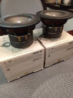
For Sale Pair of Visaton Ti100 units

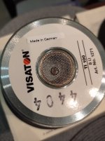
I am selling 2 Visaton Ti100 midbasses which were made in Germany and used only for measurement. The results didn't provide any evidence to dispute Zaph view regarding them as 4" speakers with minimal level of nonlinear distortions.

Pair price is 275 euro including international shipping cost. Paypal is available.

Attachments

  • Ti100 back 1.jpg
    Ti100 back 1.jpg
    66.6 KB · Views: 126
  • Ti100 pair with boxes.jpg
    Ti100 pair with boxes.jpg
    86 KB · Views: 141

F5 Power Supply Caps Seem Small

I'm speaking without knowledge here, but the capacitors that Nelson uses for the raw ps in his F5 strike me as very small. Is that because it's a Class A amp at low power where average current doesn't change? Seems that once it began operating in Class AB mode, ps voltage would start to swing around a bit. Is that not true?

If so, would larger caps help? Any downside to that?

ECF80 phase inverter circuit

I started a new project to re-home a pair of OPTs from an old Scott 299 amplifier and am looking for PI circuit opinions/ideas. Ultralinear isn't an option with those transformers so I decided to experiment with a really stiff screen supply. It's an all-tube design except for the rectifiers but I'm really impressed with the performance of the regulator and anxious to hear it. I'm going to be using the 6P14P as the output tubes (the Scott 299 used 7189s originally) and it idles right at 500 volts on the anodes. There's lots of room for screen V adjustment within a range that still provides excellent regulation so I'll be doing lot of tinkering.

Anyway, the 299 used an ECF80 phase inverter and I've re-drawn the circuit (attached) but am wondering if anyone else has used this design and how it compares to some of the others. Chassis constraints limit me to a single 9 pin miniature tube so I guess I'm not "married" to the ECF80 if there's something that is a lot better, but I've read a lot of great stuff about the tube and I have a bunch so I planned to at least start out with it. What I don't know though is how the original Scott circuit design might compare sonically to some of the others. Yes, I know, opinions and tastes vary from person to person but having never heard a working Scott 299, I thought I'd ask the guys that play with this stuff more than I do. I've been into lots of guitar amp projects and amateur radio stuff but this is probably my first "hi fi" audio project so in that regard opinions are worthwhile to me.

Enough blabber. PI schematic attached. Many thanks in advance for your opinions, ideas, suggestions etc.

Attachments

  • 2022-02-05 13_25_24-TinyCad - [7189 Amp Phase Inverter.dsn].png
    2022-02-05 13_25_24-TinyCad - [7189 Amp Phase Inverter.dsn].png
    20 KB · Views: 1,044

Help with a 3 way crossover. Zma files xsim?

Ive had these speakers now in an active setup with the woofer to midrange crossed at 400 24db slope and the midrange to tweeter being crossed at 1500 with a 12db slope.
The tweeter was measured with a 33uf capacitor on it also not sure if that changes things in this response where i mean to cross or not?
Can anybody help with a fairly simple crossover? im not sure where to get started. The drivers dont require much eq to get a very even response at those crossovers.
Is there any other programs that have crossover examples i can try out and change the values of slightly to get what im looking for? Pretty new to crossover design besides active setups.

Attachments

Question about dsp amp general capability.

My question arose because of two models of amps by power acoustic
power acoutsrik rz5-2500dsp 4x100+400@4ohm

power acoutsrik rz4-2000dsp
4x190@4ohm
My question is in regards to the rca connections. The rz4-2000dsp (4 CH) model features a rca out, and can be controlled by the dsp chip to give dsp features to external subwoofer amp likely thru the sigma studio software used to control the amp. The model I purchased rz5-2500dsp (more expensive) model lacks the RCA output port altogether. The other RCA connections are inputs for front and rear channels from the deck.

My question is what RCA would you recommend running if using a modern pioneer deck like dmh-220ex? The deck also features dsp options aswell. Does my model lack sub channel inputs or is the rear mixed with sub channel? How likely is the 4 CH amp able to control this RCA out? How feasible 2ould it be for me to solder in RCA inputs for sub channel? Or RCA out, like the 4 CH version has?

Help identifying a device

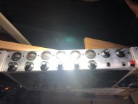
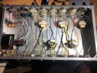
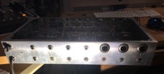
Picked up and Altec 436 a while back and this component was in the rack with it. It's homemade. There's gauges and knobs on the front, jacks on the back and transformers inside. Don't know what it is. A mic preamp? I know the folks here know what it is, when it was made and what kind of solder was used. Thanks for the help.

Attachments

  • front.jpg
    front.jpg
    57.4 KB · Views: 124
  • inside.jpg
    inside.jpg
    109 KB · Views: 121
  • back.jpg
    back.jpg
    45.6 KB · Views: 126

Amp failed on power-up

Fisher Price My First Class D amplifier, and it died when power was applied. Of course.

It's a TDA8954J on a board of my own design, configured as BTL. I can't tell whether I have stuffed the design of it, or the PCB layout, or whether the chips are just eBay fakes - there are none in legitimate supply chains.

The output is -40V, so one of the output channels is hard over. The strange (to me) thing is that I could see R14 burn, and that's just there as a fault indicator on DIAG2. Something really bad had to happen inside the chip to send DIAG2 to one of the power rails.

Schematic and layout attached - any brilliant ideas? Suggestions for a different Class D all-in-one chip good for 300W/8R or 600W/4R that I can actually legitimately buy are also welcome...

Attachments

  • tda8954-btl-layout.png
    tda8954-btl-layout.png
    319.8 KB · Views: 294
  • tda8954-schematic.png
    tda8954-schematic.png
    574.2 KB · Views: 250

Best RG59 for BNC digital interconnects

Not sure if this is forum is best to post on this issue, but here goes. I want to roll up a few digital spdif interconnects and have a bunch of Neutric 75 ohm BNC connectors for this purpose. Trouble is, they fit RG59 cable. It seems like most digital cables are RG11 or RG6. I've read that RG59 is great for RF applications but less for digital signals.

So, is it so that RG59 performs poorly with digital signals? And secondly, if the answer to that is "not necessarily" can anybody recommend a suitable RG59 grade to use? Thanks in advance. I'm blind here. Cheers

Fisher amp ICs

Hello everyone,
I'm affiliated with Mr. CC Poon, owner of Monarchy Audio Inc. in San Francisco Bay Area (It's pretty much a one person audio company).
As many of his customers already know, Mr. Poon has retired. He's trying to sell/liquidate all of his inventories. However, he's not tech savvy/familiar with all the online audio forums/marketing sites so I'm helping with 'cleaning up' his warehouse
:)
. If you know anyone (like an audio maker, or yourself) that would be interested in buying audio parts in bulk, please contact Mr. Poon directly via email (below). You can also PM me here. Thank you very much in advance.

Here's the first offer from him:
Fisher PA301 Power Audio IC

Mr. Poon still has thousands of them. The cost is US$5 per IC (The pcb is silver plated and free with the purchase) or they can be sold in a DYI amp kit for $30. You can negotiate with him too. Please see the details and pictures (including sample amp - not for sale)

Features:
.30 Watts x2 on 6 Ohm speakers
.Very easy to assemble
.Very inexpensive
.very clean sound
.bridgeable to mono amp with 100 Watt output
.flexible power supply rails(+/- 10V to +/- 30V)
.direct coupled output for transparent sound

Kit comes with:
1: 2 IC's for stereo
2: all components on pcb, including fuse holders,output coils,resistors and capacitors
3: Stereo pcb has silver coating on all traces
4: instructions for simple assembly.

Power supply components also available.
Please email: monarchy@earthlink.net

Price:
US$30 for a complete stereo Kit(power supply extra) plus $7.5 domestic shipping within U.S. or $26.50 shipping worldwide (one $26.50 Postal Flat Rate box will ship up to 6 kits)

Payment: by Paypal to our account:
monarchy@earthlink.net

IC size.jpg

mime-attachment (4).jpg

Dual Fisher IC on pcb.JPG

Fisher pcb.JPG

Fisher pair with components.JPG

mime-attachment.jpg

mime-attachment (1).jpg

Nelson Pass' Easy Peasy MOSFET Vgs Measurement

After building a couple of multi-output device MOSFET amps, I noticed that the current draw between the devices can vary wildly sometimes. Good thing for source resistors to allow load-balancing. I knew this was happening because I did not have Vgs matched resistors. So how to match them - I looked around for awhile on these threads but nothing jumped out as an easy to do HOWTO guide.

So here is the guide for dummies like me - I will call these threads the "Easy Peasy" (TM) threads. You may have seen the similar titled Juma's Easy Peasy Cap Multiplier thread. So I have been looking for an easy to do and clearly detailed way to measure Vgs on my MOSFETs for a while. Maybe it is so obvious to folks on this forum but for me, it took a tip from member Idefixes to look at Nelson Pass' article here:

https://www.passdiy.com/project/articles/matching-devices

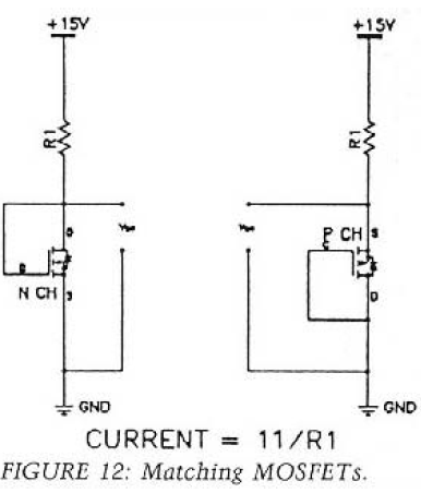
Which basically says use this easy peasy circuit:

matching.png


If you happen to have a solderless breadboard, a 2.2k resistor, a DVM, and a 15v power supply, you are all set. I happened to receive these little XL6009 DC-DC boost modules in the mail today. Slick little buggers that take almost any DC input and step up and regulate it nicely (supposedly good for 4A but the Schottky diode on board is rated 1A). Anyhow, with a trimpot I could dial in anything from 12V to 35V with 12V input and 15 to 30mV ripple depending on setting.

Here are the units, you can get them from anywhere:
https://www.amazon.com/gp/product/B00J1X4XXM/

519mFuQeXgL._SY300_.jpg


And then I have a couple of these solderless breadboards for $4 (the bundle of hard wire tipped jumpers alone is woth the price):
https://www.aliexpress.com/item/3-3...less-Prototype-Bread-board-kit/749581037.html

3-3V-5V-MB102-Breadboard-power-module-MB-102-830-points-Solderless-Prototype-Bread-board-kit.jpg_640x640.jpg


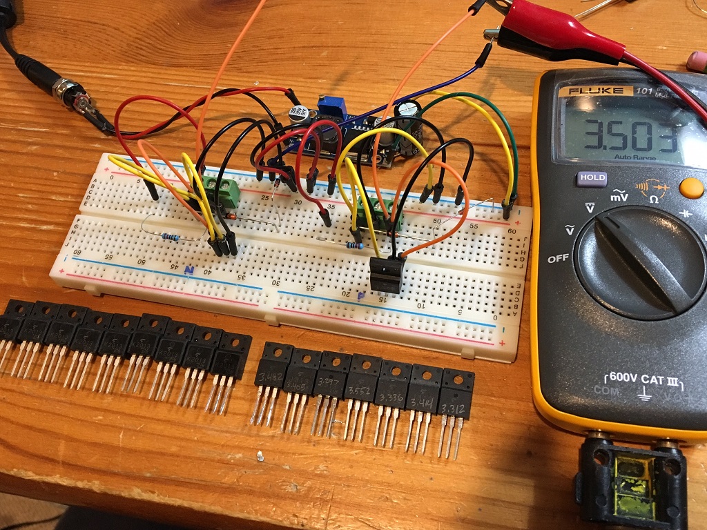
So anyhow, I proceeded to wire it up just like the diagram above and went to town measuring the Vgs of my MOSFETs at a current of 5mA.

Adjust your power supply for 15.0v, make sure your resistor is a 1% 2k2 metal thin film (1/4w will do). I added some gate protection to the circuit to avoid blowing the gates with a bad hookup or a transient using a 12v zener and 1N4148 in series from gate to ground.

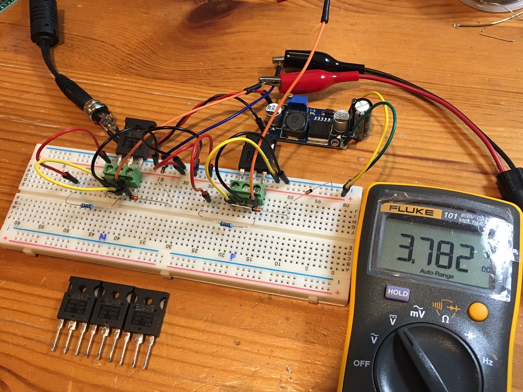
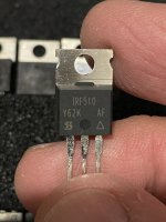
Next step is how to attach the big fat pins from an IRFP240/9240 (TO-247AC) packages? Well, it turns out that a 3-pin PCB mount screw terminal block holds the pins securely and precisely without damage (the screws actuate a lever that clamps the pins so no marring or damage to the pins occurs). Of course, a TO-220 will push right into the breadboard and that's what I did for my 2SK2013 and 2SJ313's.

So here it is in action (N channel on left side and P channel on right side):

581047d1479635401-nelson-pass-easy-peasy-mosfet-vgs-measurement-vgs-tester-01.jpg


I then added jumpers to do TO-220's here. These SK2013's and 2SJ313's have some spread but not too bad and certainly, they are proven to be functional in use as an amp and show reasonable Vgs:

581048d1479635401-nelson-pass-easy-peasy-mosfet-vgs-measurement-vgs-tester-02.jpg


It made quick work of measuring Vgs - which I just wrote onto the satin finish of the MOSFET body with a pencil. A large batch of the IRFP9240 that I got from Aliexpress for $1ea were actually matched within 0.01v for 5 of them Anyhow, I am real glad I made this jig, it's going to be really useful and well used in the future. I hope you find this helpful.

Attachments

  • Vgs-tester-01.jpg
    Vgs-tester-01.jpg
    354.2 KB · Views: 5,267
  • Vgs-tester-02.jpg
    Vgs-tester-02.jpg
    375.3 KB · Views: 4,679
  • Like
Reactions: Piotr F.

Hello from Ontario Canada

Hi Guys

I'm new to this website but have been playing with DIY tube audio for about a year now. I finished a set of Dynaco M125 monoblocks a little while ago and they have really peaked my interest on what kind of results can be achieved building things yourself. I picked up a used set of Martin Logan Aerius I ESL's the other day and am hoping to gain some knowledge on upgrading crossovers and just to have a better understanding of things.

It's cold and snowy here right now so this is a fun hobby I can do at home. Looking forward to learning lots and share some of my projects!

Transmitter Tube Testing

I acquired some transmitting tubes; the kind where the plate is supposed to glow red and act as the getter in normal operation.

I want to test them and make sure they aren't gassy. What is the best way to run them up? Do I need to let them run for a period of time at a high-ish dissipation to allow the plate to absorb stray gas molecules?

How can I maximize my chance of not causing any harm on first power-up?

Amplified signal output to line level inputs

There are quite a few threads/articles on this forum and elsewhere regarding stepping down amplified output signals to line level inputs. However, I have an application that is slightly unique (many signals, different step down levels, sound quality required, bass levels important).

The amplified signal is not from a powerful amplifier as it only outputs up to 3W output between 4 ohms and 32 ohms impedance. The input is line level (+4 dBV). My goal is to retain as much sound quality as is reasonable. In my application, there will be 40 signals, so cost is a factor and thus Jensen or equivalent transformers would be prohibitively expensive.

It is my understanding (which is limited) that transformers have the disadvantage of decreasing low frequency output. That is problematic as my application will have significant bass signals and even subsonic signals down to 10 hz (will be routed to tactile transducers).

Given my application requiring sound quality, full bandwidth signal, and cost (many channels), what is a recommended solution (e.g., voltage divider, car audio transformers, etc.)? I am afraid that this may be one of those scenarios where tradeoffs exist (cost vs sq vs signal bandwidth) and one can only have two of three. However, I hopeful the creative minds here may have viable solution for my hobby project.

KEF 104/2s - very odd problem

Hello all,


As the proud owner of a pair of 104/2s for many years, having never felt the need to upgrade, I was very disappointed to have been struck down by fate earlier and suffered one's failure.

Let me explain the problem: Playing music very loud although with no audible distortion, Roland 909 snare very loud in one track and suddenly one side loses both mid and treble. Bass drivers continue to work but the B110s and T33 don't. Taken midrange enclosure off, looked inside to see any obvious crossover component failure and can't see any. Played music through speakers and when a certain volume is reached, there's a relay-type device inside on the rear-mounted crossover that starts clicking away like crazy and is very audible. Now very distorted signal plays through the midrange and treble units, and relay device still clicks.

I was not aware that relays were used in crossovers, it says '12v coil' on top but as it clicks and is in a plastic square case, I'm confident it must be a relay? Is this some sort of protection relay that has failed, causing distortion? I was surprised a crossover component has failed before the drivers, but on feeling the amount of heat outputted from the crossover components, I'm now not that confused.

Has anyone else suffered similar failure on their 104/2s or other speakers? Is this actually a relay or am I confused? They're very early examples of the speaker with the black port surround, wooden midrange enclosure, crossovers mounted in the top and no easy terminals for the midrange enclosure removal and so I'm also worried that a schematic for mine will be impossible to find. Any advice appreciated!

CS 800 Repair (with pics!)

A while back I bought a broken CS-800 in hopes of getting some serious power for my Titanic MK-III sub on a college budget. (I got it for $75 after some negotiation with a music store owner after I saw it on his floor 😀)

I got one side working with just a thorough cleaning and since I had just one sub, I simply left channel A disconnected after correcting some safety hazards on the mains wiring. (fused neutral!)

This week I decided to revisit this amp and complete repairs. But why stop at repairs...I'm going to drag it into the 21st century kicking and screaming!

The problems with the first CS800 are numerous, some are cheap and easy to fix and others are inherent in the design (quasi-complementary outputs for example).

Two nasty sins against Hi-Fi are easily rectified for less than $10. First there is a non polarized electrolytic cap in the signal path, second the input stage is an MC1741.....which is basically the same as an LM741. An OPA134 and a metalized poly film cap are nice improvements one can make on the cheap.

Since this is a budget project and I don't have a problem with hum, the soup can sized main filter caps will be unchanged for the time being. It appears that one has been replaced as it's different in appearance than the other. The electrolytics on the drive and input boards are of course being swapped out because it costs hardly anything to do so. (plus, it's good gremlin repellent!)

Assuming everything is OK, just 6 components fixes up the drive board to better than new performance.
IMG_0279.jpg


An inside view of the chassis...spaghetti city.
IMG_0312.jpg


The repairman claimed that he had put a lot of time and money into his repair attempt and he wasn't lying! The output stage BJTs are OK! The output BJTs are Motorola with Peavey house numbers but its really 5 pairs of MJ15024. It looks like 6 but on close inspection, the first pair is a driver using MJ15020. The driver stages on the drive board were OK as well, its obviously been repaired as it has a few things from ON Semi...which didn't exist until 1999. The output clamp triacs are also ON Semi devices too. Cool stuff for sure!

I tested all the transistors, diodes, caps and resistors on both power boards and on both drive boards....everything was in order. (Don't ask how long that took....needless to say there are no cold solder joints!)

So with all those parts good, why did I get DC on Ch. B using the Ch A drive board but proper operation when using the Ch B board? The drive boards are identical; in theory it shouldn't matter what side they came from. I think the answer is simple....the repairman used the wrong opamp in the input stage! He placed a dual opamp (NE5532) in place of a single on the ch. A drive board. The pinouts are wildly different but there's no visual indication and nothing to physically prevent the swap. Hopefully that's all there is to fixing that channel.

The zener board has a strange issue...all of the 2K ohm, 5W resistors have failed open circuit. This leaves the plug in expansion ports useless. This is an easy fix although I'd love to know what took out these resistors. As you can see, things have been a bit toasty where the resistors once sat.
IMG_0302.jpg


More pics....


The most boring task of all...cleaning old thermal compound off.
IMG_0287.jpg


Completed CS800 module from the top.
IMG_0304.jpg


Completed module from below showing the drive board.
IMG_0307.jpg


Input boards with their new caps and clean pots
IMG_0284.jpg


Power Board, component side
IMG_0283.jpg


Power Board, solder side....PCBs have come a LONG way! (then again, this was anything but state of the art, even for 1977!)
IMG_0280.jpg

For Sale - Assembled and Upgraded Elekit TU-8200-R

Hello,

So, I have listed this amp on Ebay but would prefer someone from this community purchase it. If you're interested, please let me know (and you should have no problem finding the listing on Ebay where I've posted many photos).

Elekit TU-8200R. Fully assembled and working great.

I built this amp about 12 months ago and have greatly enjoyed it.

The condition is very good. Everything functions as it should. There is a scratch on the top of the chassis, a couple of scratches on one side and a single scratch on the other side. These are all from normal use (installing and removing it from my ventilated AV cabinet). I have shown the scratches in the photos.

Modifications that I made:

1. Upgraded the output transformers to the Lundahls (see photos)
2. I added a switch that allows you to change from Ultra Linear to Triode mode without opening the case and moving the jumpers.
3. Mundorf EVO Supreme Silver Gold capacitor upgrade (4 caps)

I am including 3 matched pairs of NOS, US made 12AU7 tubes. Only 1 pair has been used, the others I have never run.
I am also including a matched pair of Mullard KT-88's. I don't have a tube tester, but these are less than a year old.

All together, here's roughly what my cost was:

Elekit 8200-R - $895
Mullard KT-88 pair - $100
3 pair NOS 12AU7 (US) - $150
Capacitor upgrade - $180
Lundahl Output Transformer Upgrade - $350

I'm selling it because I simply have too many amps right now. I was just gifted a Scott 299D that I'm working on restoring, I have a finished a Bottlehead kit, a recapped NAD 3020A and I'm trying out a Hypex build. Simply have to make room.

Please message me if you have any questions. Thank you!


IMG_6234.jpg
IMG_6249.jpg

Does Anyone Recognize This Particular Tektronix 2465/2445 Oscilloscope Failure Mode?

I am considering buying and repairing a Tektronix 2465 but before I buy it I was wondering if anyone recognized the particular failure mode. I ask since some parts are very hard to get and some failure modes are likely hopeless cases.

Channels 3 & 4 appear to work but channels 1 & 2 are saturated to the top of the display (when found using the beam finder). The digital display is also skewed for all readout parameters. (See attached example of channel 3.)

So, does anyone recognize this failure mode? Particularly does this involve an unobtainium hybrid or Tek custom IC? Does it look good or bad for chances of repair?

Attachments

  • 2465.jpg
    2465.jpg
    50.4 KB · Views: 215
  • 2445 Block.jpg
    2445 Block.jpg
    148.7 KB · Views: 229

HB1 alternative tweeter with Vifa M21(?)

Hello guys,

Disclosure: I know next to nothing about speaker design. (Ive only ever added BSC and Zobels to full range drivers.) I'm only starting to learn about it really. I may make a lot of wrong conclusions or attributions so bear with me.

I refurbished an old pair of Heybrook HB1 last year and have been listening to them since. For me, it sounds very good at low to moderate level. Louder, it gets bright and male vocals take on, what i describe as, a subtle 'electronic' tone. Ive tried different amps and it sounds best with an F4, with what I have, as that cranks up gracefully.

I've attributed this, I thought, to the old tweeters and started looking for an alternative tweak perhaps. I also went to look at the specs of the M21 and the HB1 (speakers before my time)... The M21's graph response looks close to a bass woofer's to me and Heybrook crosses the tweeter at 4khz?? Shows really what I dont know or understand about crossover points...

Now I'm thinking that the 'male voice funkiness' I'm picking up is the the cone break up or xover perhaps (someone correct me). This then has got me thinking of whether its worth looking for tweeters that can cross lower than the original vifa D25, from say 2k-2.5khz LR2 to keep simple. Am I thinking about this the right way?

The M21 are new production, not refoamed. It looks like they were used by Snell and JPW as well. Where did the other designers choose to cross along that graph?

Anyway, thoughts and recommendations please.

Innersound Crossover Amp Modification to run Full Range

Hello all,

I had the Sanders Sound System 10c years ago with the Innersound ESL amp and was impressed with both the amp and speakers...reluctantly sold the two....

Anyway, just playing around with a Kaya Crossover / Bass Amp - used to drive his 10" transmission line woofer (steep crossover at 450hz) while the provided High Pass XLR outs going to another amp to drive the ESL panels. The Crossover / Bass Amp has separate Mid, Bass, and overall Level controls - set the overall Level, then the Mid and then Bass to your liking to match the ESL panels, and the overall Level controls the level on bass amp and the XLR outs for ESL panel. Also of note the Bass amp section is exactly like the standard Full range ESL amp, but with the added bass only crossover and high pass out for ESL, all done by the Daughter board.

After researching this post where someone had same Crossover / amp that had a bad crossover Daughter board, he converted the amp to run full range by just jumpering directly from the XLR jacks to the amp board.

https://www.usaudiomart.com/details/649584356-innersound-power-amp-crossover-esl300-electrostatic/

I could just wire the output XLR to the amp board, but I will try to see if I can jumper the socket to bypass the Crossover Daughterboard first.

Anyone done this yet?

Also still cannot determine what the EXP button does!!

EDIT - Roger just replied - the EXP button does nothing...just an extra button that may have had plans someday...

WTB: DIYSG Maximus-12 (or Denovo FL-450 compression drivers)

Looking for a pair of the DIYSG Maximus-12.

I've been bugging Erich at DIYSG for many months asking if he could find me the parts for the Maximus 12. I missed the boat on this kit and very much regret it. The Denovo FL-450 compression driver is the part that seems to be impossible to find now.

If you have the kit, or drivers, or even just a pair of the Denovo FL-450 CDs you would be willing to sell, please pm me.

I am in Canada, but also have a USA shipping address.

NAD C350 Output issue / Extremely low Volume

Hey there good people

My NAD C350 ain't working right after about a year of not being used.
Always worked like a charm before it was put away.

The speakers connected to the amp itself will only play on the right channel and extremely low, but when hooked up to my NAD power amp 214 it plays perfectly through the power amp.
So it seems like the issue is only with the output through the C350 speaker outputs..

Anyone got an idea as to what I should check ?

(Just wanted to point out that I have absolutely no idea about how these things work or even how to use a multimeter, complete electronic noob here)

Best regards..
  • Like
Reactions: hifisucks

2 band EQ Guitar pre-amp | Help please!

Hi guys,

I hope you all had a merry Xmas.

I have been building a guitar pre-amp to put in some of my home made guitar builds. I managed to get my hand on a schematic from: https://robkiddhomepage.wixsite.com/robkiddmusic/project-berocca

This is the schematic (which I re-designed to have a bypass switch):
1640774582243.png

The schematic is great and works ok. However, when I implemented it with some of the recommended op-amps (lm358 for example - not the lm4562, I changed that later on), I found the sound to be muffled and not as detailed as I would have liked.
So in my haste I bought some lm4564/lme49720 which seemed to be a great idea at the time. However swapping the lm358 for the lm4564/lme49720 yields some strange behaviours (to me):
1- When I first plug the system the sound is quite thin, lower in volume and quite distorted compared to the original signal. The filters seemed to work but since the original signal is bad the output sounds bad.
2- If I pull SW1A out (it is setup with a 3 pin connector) and touch pin 3 with a short resistor's pin (I can hear a loud buzz), then plug SW1A back the sound becomes normal (very detailed and exactly what I was looking for).
3- If I now use SW2 or remove the 9V battery to open the power supply circuit (setting off V+ to 0V), when I close it back to provide power again the circuit is back to the initial thin distorted sound.

I have tried a couple of things (including adding a 0.1uF capacitor to connect V+ to the ground) but nothing will do. I am starting to lose it and I hoped some of you guys could help me out.

Any help would be much appreciated!

Cheers
Rejerh

Source in Midwest USA for large cabs for 21" drivers - is there one?

I purchased a nice pair of 21" subs and I would like to put them to use. Unfortunately pretty much every high-quality cab I can find is physically too small, meaning narrower than the driver itself, which has a frame OD of around 21.5". If I want to go vented the cabs would be huge, so I may just opt for sealed. Even so that would have to be at least 8cuft if possible.

What are my options for ready-to-build cabs, if anything, or should I just build the pair from scratch myself. Did I mention I am a terrible woodworker? These will be going in my living room, so they need to have a relatively nice appearance.

I live in southern Michigan, so if there is anyone within a few hours of here that can build something for me I would love to hear about it. I am open to all ideas at this point. Thanks.

-Charlie

Another 100W hifi amp

Hi,

After successfully building my 250W amp, I designed it's low power version with some improvements. as 100W is sufficient enough for home use I removed two output pairs from 4 lowered the rails a bit, now we have a decent 100W into 8 ohm amp.
Simulated it in multisim, and below are some figures:
Supply voltage: +/-50V DC
Power output: 135W into 8, 260W into 4ohms
THD20: 0.005% @ 135W into 8 ohm load
THD1: 0.001% @ 135W into 8 ohm load

I designed the PCB in sprint layout, got them manufactured locally along with the power supply PCBs.

150W_hifi_updated_zps42c8017a.jpg~original
[/URL][/IMG]

Clipping_zps8873f35f.jpg~original
[/URL][/IMG]

150WFINAL_zps1f393e7e.gif~original
[/URL][/IMG]

PowerSupply_zpse189d2b5.gif~original
[/URL][/IMG]

IMG_20140324_221515_zps557010e3.jpg~original
[/URL][/IMG]

IMG_20140324_220302_zpsabd5d6e7.jpg~original
[/URL][/IMG]

IMG_20140324_220144_zpsce55d2ff.jpg~original
[/URL][/IMG]

IMG-20140328-00381_zpsfe763dfb.jpg~original
[/URL][/IMG]

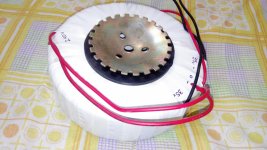
Power supply with 66000uF of Nichicon capacitance per rail, 35-0-35, 500VA toroid.
Sound is very good, powerful bass and very detailed and open mids, highs.
Here's the link to the video: DIY 120W amplifier sound test - YouTube

Cheers!!🙂
Aniket

Attachments

  • IMG_20140328_171342.jpg
    IMG_20140328_171342.jpg
    412.9 KB · Views: 530
  • IMG-20140328-00385.jpg
    IMG-20140328-00385.jpg
    924 KB · Views: 470

Il Penitente amp kit packages

Presenting thread here: https://www.diyaudio.com/community/threads/il-penitente.382007/

Schematic and pcb screenshot post #1 , plenty of pictures after .

Tips and Tricks thread - will open, sooner or later (if needed)

Reading entire thread is advisable , same as inquiring any technical question there : Be sure that you are aware of all things electrical and mechanical !


Pcbs are made for UMS , mounting directly to heatsink


Do not hurry - read , think , ask and only when you feel that you want it and can make it , proceed ...... advice which I'm finding applicable on practically anything .

For anything else , write either here , send PM or directly to >zenmodiyaudio@gmail.com<

Prices are mostly dictated with small scale nature of operation (as always is case) and time/work involved in matching and soldering little buggers.

For ordering , contact me at above written e-mail addy .


Kit options :

Option 1.
  • LCH pcb ,
  • RCH pcb ,
  • all smd buffer JFets (Toshiba 2SK2145BL) presoldered ,
  • smd precision CCS chips presoldered
  • all smd caps and resistors presoldered ,
  • 4pcs of 1uF MKC caps (for important bypass positions) enclosed.

Full price , including Paypal fee and P&P for registered shipping all around the Globe - 135E

Option 2.
  • LCH pcb ,
  • RCH pcb ,
  • all smd buffer JFets (Toshiba 2SK2145BL) presoldered ,
  • smd precision CCS chips presoldered
  • all smd caps and resistors presoldered ,
  • 4pcs of 1uF MKC caps (for important bypass positions) enclosed.
-all multiturn trimpots
-IRF510/9510 drivers
-cascode bjts
-optocouplers
-all electrolytic caps (all Panasonic/whatever Brand name I lay hands on , Elna Silmic II for one signal route position)
-1 pins for few test points
- jumper pins and jumpers, in between buffer and autoformer
-all (MF 600mW) resistors
- rail resistors (0R22/2W)
-T0220 heatsinks - 4pcs
-NO BJT OUTPUTS - ZM being lazy to get those in quantity
-etc.

to recapitulate - everything what goes on pcbs , excluding signal xformers, BJT outputs and pcb/outputs mounting screws/nuts/washers ;

Full price , including Paypal fee and P&P for registered shipping all around the Globe - 185E


If I have everything in drawers in moment of order , can ship in a week time;
If I don't have any of normal parts in drawer , shipping could be delayed up to 3 days;
If I don't have pcbs in drawer , shipping could be delayed up to 2 weeks;
If I don't have most critical part for getting in my neck of wood - CCS precision chips , shipping could be delayed up to 3 weeks.
All in all - you all know that ZM is slow, but inevitable

Handy Addendum (in short : HA!):

-Cap Bank pcbs - set of 2pcs; dual rail, CRC (pads, if you want differential/whatever fancy you type of CLC), snap-in up to 35mm Dia, resistor and pads for LED, position for 10mm NTC connecting Audio GND to chassis;
-NTC pcb/ FW style Soft Start - set of 2pcs; each having place for 2 independent NTCs;depending of arrangement of primaries of Donuts you're using, you'll need either one pcb for two Donuts, or one pcb per Donut

HA! set is 25E more

see pics for HA!; lazy to search do I have photo of NTC pcb, but who cares
Recap?

I have a pair of Jamo 507 speakers, I have no idea how old they are exactly, my guess is they are about 20 year old.

Long story short, one side sounds more muffled than the other. The twitter doesn't seem completely dead though. I am no expert, does it sound like the crossover need a recap?

The speaker has a twitter, 2 woofers, and 2 subwoofers. It is biampable, 2 of the larger caps looks like they belong to the bass section. That leaves the other 2 caps. 1 is a film cap that says 100V, but does not mention the size, I am guessing I should leave this alone. The other is a 10uF electrolytic cap, does this sound like the problem here?

Or is this how twitter begin to fail? Do they typically just put out less and less sound or do they normally just stop making sound? The front mount of the twitter isn't a normal round shape, I am guessing I will have a hard time finding a twitter that physically would fit in there.

Improved current source/sink

Hi,

Here is a simple trick to improve the performance of the two-transistor CCS.

This type of current source has a good regulation vs. variations of the output voltage (= high output impedance), but behaves rather poorly wrt. variations of the auxiliary (bias) voltage (= non-zero transconductance).
By adding a single compensation resistor, a huge gain can be made.

In this example, a 10mA current sink, resistor R4 has been added.

The circuit on the right is the regular CCS used as the reference for comparison.

Without R4, the current variation amounts to 24µA for 1V.
With R4, this variation is only 0.27µA, almost a 100 to 1 improvement.
The value has been fine-tuned for the optimum, and R2 also had to be altered slightly to keep the same current.
I have found the values empirically, it should be possible to derive a formula.
I think it should look something like this:
The ratio of R4 to R2 equals 2(Iout/Ibias)(Vbias/Vbe) (to be checked, at first sight, it seems to work).

It is not necessary to use exact values: the second example uses the nearest standard values, and the delta current has increased to 0.7µA, but it is still a worthwhile gain.

With this method, the PSRR of an amplifier could be improved by 20 to 40dB.

Attachments

  • iCCS.GIF
    iCCS.GIF
    34.2 KB · Views: 3,287
  • iCCS2.GIF
    iCCS2.GIF
    33.5 KB · Views: 3,210

F5 Listening Impressions & Discussion

Hi F5'ers...

My friend Rick decided some time ago to try his hand at building an F5. Since he is somewhat a newbie when it comes to ground up construction, the F5 appealed to him due to the almost complete lack of parts! 😉

So, he brought his first version, on plywood, over for an audition.

It wasn't bad, but it sounded a bit "funny" - somewhat thinish and somehow a bit "uncorrelated".

We were listening on my horn system which consists of a relatively rare Japanese compression driver from 300Hz up and a 15" midbass "filler" down to my Quadripole subs... the main amp, in this case w/F5 substituting runs the horn + woofer. Horn is 109db (padded down to meet) the 15" at ~99dB (real 99dB, not wanna be). We also ran it direct to the horn.

The beauty of this arrangement for me is that there is ~10dB sensitivity difference between the horn at 109 and the woofer at 99, which corresponds almost exactly to the gain diff between my main amp (Symphony No.1) and the F5... voila magique! Auto level matching!

Long story short, it sounded good, but a bit lackluster.

Rick stopped back several times, each time with an upgrade:
- resistors
- power supply
- wires
- layout

The details of it aren't totally important.

What is important to me is that we recently auditioned it vs. a homebrew all Tango 300B amp, a Welborne Labs 300B amp, a Cary 811-3 amp, and of course my Symphony No.1 amp.

We used WE300B and others... fyi.

Very very easy to hear what is going on with this system...

Bottom line subjective result for me is that the F5 seems rather sensitive to details of implementation but is silky smooth on the top end, beating out the SE toobes that were here by some degree, seems to not create much if any sibilance (that HF grain on the top of voices)... now I do have to find out why this is so - but even if it is a flaw it is a really really nice flaw!

Still not sure about the sense of dynamics, or if the darn thing is just super clean sounding, so that is what is going on or not...

Quite an exciting amp so far!

PS. not sure that this is really a good amp for most folks unless you have very high efficiency horns like I do, or a very very small room... bridged seems interesting though...

_-_-bear

For Sale Salas Reflektor D power supply

For sale a Salas Reflektor shunt regulator in full working status. Parts are from original kit. I'll supply additional Vishay CFP resistors for CCS and leds of various color (setup resistors and leds are in bases for easy swap, I could remove them if asked).

SOLD

Attachments

  • Reflektor_01.JPG
    Reflektor_01.JPG
    269.6 KB · Views: 273
  • Reflektor_02.JPG
    Reflektor_02.JPG
    263.4 KB · Views: 281

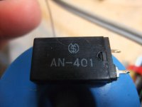
Datasheet wanted for Auto Reset Circuit Breaker used in NAD Amps (Type "A-40"/"AN-401")

NAD's part No. of models 3240PE/7240 according part list in the service manuals (Breaker BK1, 2) are the follow :
"0045—400—0—00" or "0045—401—0—00" or L422Y001H01 or L422Y001HQ1

If I go to "Google" and use this part-No as keyword, I find only various service manuals from NAD.

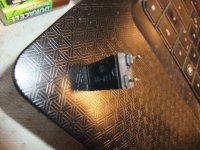
In the attachment, three images, first image shows a version from an older 3140PE and the second and third image a version from a newer device of this model.
Obviously there is to read still the same logo, but different type No.
Maybe one of the guys here know the associated manufacturer.

If I have the data sheet from this genuine parts, actually I must be able to find a replacement part from here:
https://www.glosotech.com/products/item/Thermal Circuit Protector - Breakers/E7 MINI/
Thank you very much.

This auto reset breakers often mentioned in various cases here on diyaudio:
post #27 and the follow postings under
https://www.diyaudio.com/community/threads/nad-3020-problem.375191/page-2(describes the aim of the two feedback pads from the power buffer output and the speaker terminal - before BK1 and BK2 and behind)
additional post 10 under
https://www.diyaudio.com/community/threads/nad-7020i-sudden-death.363517/post #11 under
https://www.diyaudio.com/community/threads/circuit-breaker-for-amplifier.343490/and post #8-14 under
https://www.diyaudio.com/community/threads/nad-3140-strange-phenomenon.323850/and
https://www.diyaudio.com/community/threads/nad-3020-problem.375191/unfortunately without a posted datasheet anywhere.

Even this URLs don't provided the wanted information.
https://www.vintage-radio.net/forum/showthread.php?t=93073https://www.altronics.com.au/p/s5625-5a-pcb-mount-auto-reset-circuit-breaker/https://raytechintltd.com/products/na1-1-6ahttps://www.ecvv.com/product/4498385.htmlhttps://www.kuo-yuh.com/97-series-auto-reset-circuit-breaker.html

Attachments

  • DSCF8262.JPG
    DSCF8262.JPG
    495.3 KB · Views: 161
  • DSCF8260.JPG
    DSCF8260.JPG
    556.9 KB · Views: 117
  • DSCF8258.JPG
    DSCF8258.JPG
    328.8 KB · Views: 140

Fuse Amp rating for Anaview ams0100? 1A to low?

Hi! I have recently bougt two Anaview ams0100 module for use in BTL. The output power is 120w into 6 ohm load, and probably around 100w into 8 ohm. The internal fuse is rated 1.6A and seems to be a real hassel to have it replaced. I was wondering what external Amp rating the fuse should be? I bought two 1 amp rated fuse, is this to low? I have seen online that people use 1,5A fuse, but could not find and good audio graded fuse at that rating. 1A 230-240V should be at 230-240w, and that seem to be very unlikely to be feed to a high efficent Class d amp. I doesnt use alot of power, i have quite sensitive ears so i probaly will not use more then 10w.

Is a higher amp rating a must or will 1A fuse be enough?

Best regards Jacop

Acoustat MK-131 Preventive Maintenance

This was also posted under the Acoustat Answerman thread....

New here to diyAudio. I appreciate the wealth of information and knowledgeable experts here. I recently acquired a pair of Acoustat 2MH's. I've been a big Acoustat fan for 40 years since I got my first set of Model 2's in the early 80's. I haven't yet had a chance to dig into the MK-131 interfaces (the speakers are fully functional), but my question concerns Preventive Maintenance. I want to do as few modification as possible. I understand the "C mod" is highly recommended, but I would prefer to keep the speakers as original as possible. So, my question is this: From the schematics I've seen on here, it seems that there is a single electrolytic capacitor present in the interface. Am I correct in assuming that this electrolytic cap is the only component prone to age-related failure, and therefore the only component that I should be concerned about replacing (given my desire to make as few changes as absolutely possible)?

Thanks for you time.
Projects by fanatics, for fanatics
Get answers and advice for everyone wanting to learn the art of audio.
Join the Community
507,758
Members
7,887,198
Messages

Filter

Forum Statistics

Threads
406,170
Messages
7,887,198
Members
507,758
Latest member
Cindy