Be prepaired this one is going to be long .....
MY diyaudio journey ages 25 this year ...that is a long time ...through these years i got the chance to interract with some wonderful people ...
--Obeserved the first mistakes of CarlosDX and the way he snaped out of them( polite and cheerful person )
--Having huge arguments with AndrewT where obviously Andrew was right and i was wrong bless his soul
--Observing NP's work , approach , target group, and traps installed by him in his comercial products
--Some work with Rod ESP products
--some with Wahab
--Some interesting things with the Dutch family ( i like the Ducth i think that they are very nice ppl )
--met Jan Dupont what a grate guy !
-- Long and deep emails with Hugh Dean
--Pointless arguments with Dr Bora
--Niko Russ and Bob Carver that actually exchanged a few emails with to discover that Bob eventhough a legent spared some time to advance one of my projects
--Spoken to Tim De Paravichini on the phone ( bad bad expierence a very arrogant person )
Though met some also very grate people that said just a few things that changed my approach for life ,without additute and some words written without sauce : Bob Cordel ,John Curl and many more with deep knowledge and a humble and low profile .
At 55 today collecting all these info for such a long time from so many different people made me a better repair man .... With above 2500 repaired/restored machines every year in my company i think i am setting the standards in the repair industry in my country and notice that Greece is a small country and been in economical issues for years now ...
But it doesn't stop there ... to repair or restore 2500 machines means that you talk with way too many people to get there ...
So i collect that also
Which amplifier versus type of mysic, versus topology , versus power ,versus class of operation,versus speaker and so on and on
what people in class A?
what people in classAB?
why some of them still in almost class B?
,who finds pleasure in New class A and why ,
Why there still audience For NAIM or musical Fidelity products and so on and on ( sorry i had to write that 😀😀😀😀😀😀 )
That made me a better repair man , that also made my tunings better ,that made my upgrades better ( stollen all the secrets from expensive models and apply them to the small models ) and of course that made my suggestions on the amplifier choice questions very very correct as long as i had the above questions answered my suggestion was 1000% correct .
So after that long intro i will guarantee that there will be no listener that finds pleasure in house music and have or like a Goldmund mimesis amp ....house music require beefy , kicky and speedy bass , super crisp and fast high , while middle area is an area of no interest ...This is the exact opposite of what a mimesis can do....
Listeners that like Goldmund mimesis will go for vocals , strings and pianos , saxes and other blown things 😛,in general things in the "classic area "
So the mimesis is a European version of a Sanyo Plus 55 or a bit more sophisticated version of a HAfler DH200... there is no magic here or a circuit that was delivered from NASA .... Also if check the audience of Sanyo Plus 55 , Hafler DH 200 and Goldmund you will notice that the listening porogram is the same ....
So to my understanding a Goldmung mimesis didnt deserve such an extensive thread arround him or a group for resurrecting the weird and badly constructed module from the dead ......
Now from the long P3A journey i have learned that listeners in general will comment a symmetrical vas as very accurate result while they will comment a bootstrap as a more musical result .... for undifined reasons a "more friendly to the ear result " without explanation if this is right or wrong ....
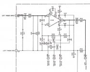
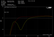
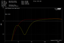
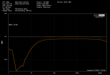
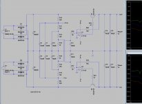
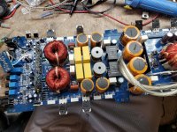
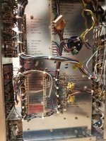
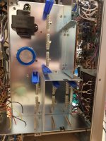
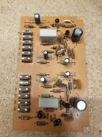
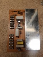
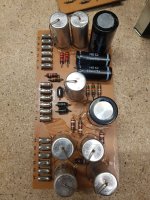
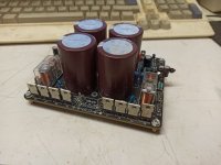
So i converted for a client a "module broken" mimesis, to a mimesis /ESP 101 hybrid .... The input stage is one LTP ,then a bootstrap Vas , a bias scheme , then the drivers ,protection and output is original Goldmund ..... Distortion is very very low , bandwidth exceeds 100 k , bias is 60ma per tranistor 240 total ...circuit is solid rock and stable , client enjoys the amp driving a pair of Harbeth which is a very detailed speaker and will reveal many details or mistakes if exist but on the other hand easy to drive .
Client states that next to the Goldmund the bass is far more controlable and accurate and the highs have 2clicks of more sweet sound than the original circuit while in the middle area almost nothing changed next to the original circuit ...
so the client is my age and been in the sport for 40 years with many systems and he had the same things in his mind about Harbeth ...which as said above is a revealing speaker but easy to drive in general ..
So he took the amp for a test drive in a friend's house to drive a pair of b&w dm 604 s3 ...Obviously the amp didnt have the power to drive completely the
B&W But the picture was alike and at some points even a bit sweeter in highs next to the Rotel RB991 that existed to the friend's house .Up to a point the drive ability was fine but not enough ....
Nobody asking for a schematic now, it's not going to happen !
The point of the thread is to make some people think out of the box and start thinking that there might be other solutions to a given problem.
Above all i have to thank people that done the same to me and you for reading the story
Sakis

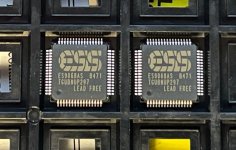

 In a DAC output stage it "overperformed" almost every modern, well respected dual opamps I've tried as far as speed, dynamics, and liveliness is concerned.. (in my system, of course
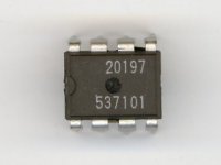


