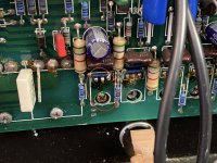
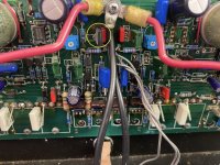
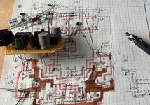
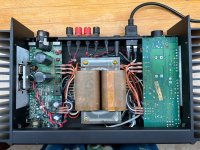
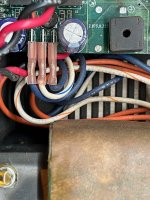
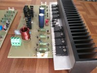
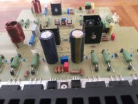
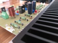
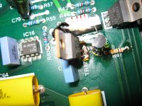
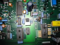
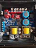
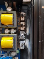
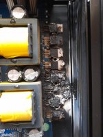
Marantz Cd player SA15S2

Hi
My Marantz cd player has stopped working.
Symptoms;
1. When powered the player
The display says power on but does not go beyond to indicate the no disc.
2. The cd tray has stuck.
I opened the top cover and released the tray by carefully rotating the gears.
When I did that the tray mechanism become very slack and indicates no resistance when I push the tray in carefully.
3. Still the power on position did not go beyond the no power indication.
Anyone who could explain to me the reason for the above issue and how I could get over this issue.

Regards

Mohan

Lawn mowers

Hi lads,

After some struggle with a corded Mountfield I decided its time to be a real man 😀

I have a small lawn, around 75-80sqm. Main issue with the corded one was I have post lights and a fountain which makes doing about 1/3 of the lawn a bit hard as the cable likes to get stuck on these. Also, when grass is wet this one`s not collecting it properly.

Would you say it makes sense to buy a petrol mower - been eyeing a Honda HRG 466 SKEP but suddenly got slapped by a thought - isn`t a large 46-50cm self propelled mower not going to create other problems in a smaller garden? Or be Clarkson and get all the power & pistons & smoke 😀
  • Like
Reactions: Capt Grogg

Dynaco SCA80Q Issues?

I've pretty much completely rebuilt my SCA80Q with parts and help from Dan at updatemydynaco.com; all the big capacitors, fully repopulated both preamp boards, new input jacks, new speaker binding posts, new balance control, new caps and resistors on the front panel switches and pots, and new caps and transistors on the power amp boards (the power amp parts were from an eBay supplier).

The amp sounds better than ever, except for a few vagaries....

1. I have lost the left channel completely on two occasions. Lost, as in, NO output even at full volume. No hiss, hum... nothing. Swapping input channel leads confirms that the issue is internal in the SCA80Q. With volume full up, no inputs connected, there is the expected hiss and very slight hum in the right channel, but absolutely nothing in the left channel.

2. There has always been a significant turn-on "thump," and it is still present; if anything, it's even stronger than it was before the rebuild.

3. Here's where it gets weird. The solution to item number 1 above, on both occasions, has been to turn off the amp, wait a few seconds, then turn it back on. When doing so, the turn-on thump is severe... almost a turn-on "CRACK," meaning not just the "thud" usually heard, but a strong full-range POP. After that, both channels work and the amp sounds pretty good.

Have already received advice to swap the pad 19 leads from the pre boards to the amp boards to narrow down where the problem is, and will do that. Anyone have any further insights/places to look? I had originally thought that the issue may lie in the selector switch contacts, but the fact that turning the power off, then back on, seems to negate that. Who knows.

Thanks in advance for any suggestions.

Audio Grade rail caps vs. datasheet specs

I dread starting a capacitor discussion as much as anyone, but I've been looking at datasheets on various brands and types of capacitors to use for the +/- power rails on a SS power amplifier. I work mostly on tube amps, so I have years of experience knowing which type and brand to use for a given application. With SS rail caps, I'm not as sure which way to go.

For example, there are the well-known Nichicon Audio Grade lines like LKG and others. But if you look at the datasheet specs by other companies, you see that in recent years, they have managed to bring ESR down in some cases to half that of the Nichicon Audio Grade capacitors and have increased ripple current figures. Companies like TDK/Epcos and United Chemi-con seem to be leading in this area.

Reading sites like the Elliot Sound Projects pages, there's an emphasis on low ESR for SS power supplies, and I've seen some techs using arrays of smaller capacitors to replace single larger capacitors to lower ESR by putting them in parallel. In other words, I see emphasis on this parameter from multiple sources.

On the other hand, Nichicon specifically markets several lines of capacitors specifically for audio, and I've used several of them with good results in signal path applications like KZ and ES Muse types. For the most part, however, other companies simply don't market their capacitors in this way for specific applications. (Elna comes to mind as another company that does, but they are mainly for signal path.) Nichicon doesn't state exactly what it is about their audio grade capacitors that makes them better for audio.

Making comparisons even more difficult, you have to do a pretty deep dive into the datasheets to compare apples to apples since the various companies don't all report their specs in the same way. Math is involved.

So if I'm looking for a 3300uF capacitor, I could go with a Nichicon LKG "Type II" with 120mΩ ESR. But there is also a Vishay/BC Components capacitor from the MAL2056 series listed as having 67mΩ ESR @ 100Hz and 40mΩ at 10kHz. It's also listed as a 12,000 hour part compared to 1,000 for the Nichicon. Ripple current is about the same as Nichicon, but for a longer life.

Then there's a TDK/Epcos cap from the B41505 series that claims 56mΩ ESR @ 100Hz and 55mΩ ESR @ 10kHz. It also claims around 60% greater ripple current than Nichicon or BC Components and a life of 5,000 hours @ 105C, 12,000 hours @ 85C, and 25,000 hours @ 40C. Looks like this line has been around since 2016.

On paper, it looks like the TDK capacitor would win the specifications contest, but does that lead to better sonic performance specifically for a power supply rail capacitor? Would Nichicon's audio grade sound better even though Nichicon is pretty vague on why that would be the case? Or is it simply the case that Nichicon pursues the audio market in a way their competitors do not? I've used Panasonic and Chemi-con capacitors in some power supplies in the past, as well as Nichicon, but I can't claim one sounded better than the other. They were all very good. And is that the answer? Has performance of all modern electrolytics by top companies gotten so good that it's just splitting hairs as to which is "best"?
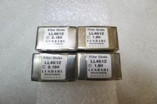
aleph power supply

good morning everyone ! looking at the projects of the aleph amplifier from the KKPCB website I saw that the power supply stage has fast diodes and a pigreco filter formed by 4 capacitors and an inductance for each power supply branch! Have you tried this type of power supply? Would it be possible to replace the coils with resistors?
Attachments

  • Screenshot 2022-04-20 at 08-32-36 PASS LABS CLONE - Aleph-3 PS-X2 Amplifier Power Supply PCB.png
    Screenshot 2022-04-20 at 08-32-36 PASS LABS CLONE - Aleph-3 PS-X2 Amplifier Power Supply PCB.png
    29.7 KB · Views: 361

Compact PCB for Doug Self's EQ Design

Hi,

I'm trying to step up my PCB game designing a board for Doug Self's EQ/Preamp from LinearAudio Vol. 5. I know, there is a nice "official" board available here. However, I would love to fit this device into a Modushop Galaxy GX247 case. That's about 220mm wide and 170mm deep.
My expirience with designing my own PCB is limited to much smaller endevours. I've done simple home-made single-layer boards but no professionally manufactured boards of this complexity level. But maybe I can still pull this off 🙂
Since building Bonsai's X-Altra Phono Pre made me realize that soldering SMD isn't half as bad as I had imagined it to be, I think I can get the design to fit into the case by using 805 SMD parts where I can.

I tried to follow the best practices that I'm aware of and came up with the following board. Most tracks are .4mm Some are wider, none are smaller. I treid to set up a good star-ground structure and to make the power supply rails clean and staight. I don't know if I should consider any ground-planes. Not sure where that would make sense.
Also, I still need to work out whether I need heat-sinks for the regulators...

It would be great if some of you with more expirience could take a look and point out any glaring oversights, improvements or other tips.

Here is the PCB so far in what I hope is a high enough resolution to make out things...
PCB.png


Here is the GND network highlighted:
GND.png


And this is the VDC+/- power supply rails
VDC.png


And finally a 3D view...
Screenshot 2022-02-05 at 11.07.33.png


Would be great to get some insights on what might be missing to make this work...

Cheers!
Lars

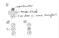
Scaling up a 4inch upper mid and tweet output

Here I need a qualified opinion from the attending gurus please (as much as possible so pls feel free to just go at it. Thx).

I am listening to LX521s right now (with my 12inch sealed bass units). I used a similar driver/XO arrangement in my home brewed OBs:
https://www.diyaudio.com/forums/multi-way/123512-ultimate-baffle-gallery-259.html#post5670164

I actually liked that driver complement better (Visaton AL200 + SS 10F/4424g00) than the SL drivers. So I am thinking of making a BOX speaker to put on top of the LX521 sealed bass. I really love the SS 10F driver and would like to stick with it if at all possible.

My tentative design goals are:
1) box size around 12 x 14 x24 inch (W xD xH)
2) run one (or two) AL200(s) from under 100Hz up to 700Hz,
3. use 10F from 700Hz up to TBD but:
3.1) use the lower distortion 8ohm version (10F/8424) but get the sensitivity back up to 90dB or better?
3.2) increase the max SPL capability so the drivers run low on displacement and distortion at higher volumes?
3.3) increase directivity and "throw" into the room (listening distance is 12-13ft) if possible, so the direct to radiated sound ratio gets better?
3.4) introduce a super tweeter if necessary to prevent comb effects (may have to experiment eventually to see if that is an improvement).

Combing may present less of an issue at this listening distance but should still be addressed within reason and that is why I am asking the questions.

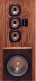
I am thinking so far something like these arrangements:
3x4inch_driver_layout_for_upperMid_&_trebble.png

Inspiration_InfinityRefStandardII.png

Also, an out-of-the box: if a synergy like upper mid is possible with a cylindrical supertweet in the middle:

SynergyMidDriver_forBaffleMounting.png

Does any of this look doable to you?

Btw I am planning on 3-way active here between AL200, 10Fs and the tbd supertweet, so one EQ per amp channel is available. (actually 4-way with the 12inch sealed sub under).

B&K 607 & 667 Testers, CHART of Unlisted

Hi,

I have been compiling a rather comprehensive listing of tubes not found in the latest tube-chart I have for the B&K 607/667 Testers. My B&K setup-chart # is 497-015-0-180 and I don't know exactly when that was published as it doesn't say in the booklet. Living in Europe obviously I come across quite a variety of European tubes and some aren't listed by B&K. I set about finding as many missing European & US tubes as possible and x-ref them to already listed European or US types to obtain setup-data. As you will see it turned out to be quite many. When direct x-ref wasn't possible I still listed the tubes but w/o the LOAD setting. It will enable you to still test the tube to a degree and becomming familiar with using the 607/667 testers you'll soon recognize what LOAD-settings are sane and what aren't.

This list is for NON-Russian tubes but a Russian ditto is on the way and will be posted here as well.

The reason for doing this is that I'm very happy to be using the B&K testers. I have one of each, but they're really the same except for the case. When they arrived I renovated them, replacing ALL resistors as they were out of range. Also the electrolytic cap's needed to go. To finish renovating I bought a 100MOhm resistor to do the required calibration.

Now they're my favorite testers for catching faulty tubes showing grid-current/leak. To my knowledge no other testers are able to do this as well and when dealing with used tubes this is a must. I didn't anticipate that so many tubes would suffer from this problem but they do.

If you spot any errors in the list, and there is bound to be some or if you have any additions I'll be very happy to hear from you.

Wow, I would have thought more people were using the B&K 607/667 testers. Still, those who do knows what great emission testers they are. Especially for detecting grid current/leak ! I'm attaching the latest chart, ver.1.3 which includes additions and corrections. The bulk of compatible tubes are of course already in the chart and now finding more is a very tedious work. Also I need to confirm settings by actual testing of NOS tube-samples on hand. Some few are already done and more will follow. Have a look at the new chart...

rgds,

/tricomp

The chart grew extensively. Now about 60 pages of setup-data for non-listed, non-Russian tubes. As I have a lot of NOS German Steel Tubes, Socket Y8A (EF11 etc.) on hand I made an adapter for testing these as well. An adapter for the European Side Contact Base P8A (EL6 etc.) will follow as I also have a stash of these tube variants. A Rimlock B8A adapter (EL41 etc.) will surely be added too. The B&K works just fine with the adapter-solution for testing real vintage tubes, but of course it should. These tubes aren't any different from modern tubes save the sockets. I'm impressed that the previous chart was only downloaded a single time. I can't believe no-one knows about the B&K 607/667 testers. If that's the case I can say that you don't know what you're missing ! This beauty will tell you about any potential grid leak problem way before any other emission tester imho. And, ..now it has one of the most comprehensive additional setup-charts available for any emission-tester !!

Attachments

Assistance to refreshen up crossovers on a Non Branded Pair of Loudspeakers

Hi All.

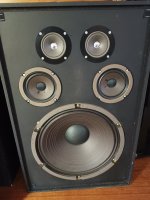
Just came across a pair of 3 Way Loudspeakers which I'd like to freshen up.
Previous owner said the high notes were absent.
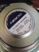
Each enclosure has 1 x15" Nisco Woofer, 2 x 3 1/2" Japanese Mids, 2 x 2 1/2" Japanese Tweeters.
Firstly I found a non soldered section of wire feeding the mid drivers had separated.
The other thing, that puzzles me, is that the mid capacitor is feeding the -ve terminal on the mid range speakers.
Existing crossovers:
+ve signal to large air core inductor, then to +ve terminal on woofer.
+ve signal to 8 µF electrolytic cap, then to -ve terminal on midrange speakers.
+ve signal to 2.8 µF electrolytic cap, then split, one going to +ve terminal on tweeter speakers, and another going to a smaller inductor which then goes to -ve return.

Is this correct?
Should the 8µF electrolytic cap be feeding the negative on the midrange drivers?
And, is it normal to have the 2.8µF cap feeding both the tweeters & an Inductor (especially as the Inductor then goes back to -ve enclosure terminal)?
Also, are these drivers of any value(the 15 inch drivers look like they could move some air)?

Attachments

  • Speakers 15 inch 1.jpg
    Speakers 15 inch 1.jpg
    398.4 KB · Views: 182
  • Speakers 15 inch 2.jpg
    Speakers 15 inch 2.jpg
    433 KB · Views: 229

Question on Chassis Ground

Hi All!
I'm building an RH84 and have grounded it as follows: AC line green direct connection to chassis very close to IEC socket, all else star-grounded back to PT secondary. Upon checking continuities, I realized my secondary grounds are all isolated from the chassis ground (all my star-ground connections used insulated terminal strips). Is this an absolute no-no? What are the pros/cons of doing this? Thanks!

Power Supply for Subwoofer

Hi everyone. I want to build my first own Subwoofer for home cinema and music. I plan to use a TPA3255 for it and chose a "Hertz S 300 S4" (https://hertz-audio.com/product/car-audio-subwoofers-uno-s300s4/) (I know it is a car subwoofer, but thats the one I already had).

My question now though is: How to design the Power Supply? For low frequencies and this chassis I need some power so toroidal transformer are large, heavy and expensive. That's why I chose a switching power supply. The next thing would now to add a filter and for toroidal transformers you would need to filter 100/120Hz very much. But the switching noise of the switching supply would be at i.e. 80kHz or more right? Even if that is not filtered at all, the chassis wouldn't be able to play that frequencies PLUS nobody would be able to hear it anyway. So what filter should I build? No filtering or just the internal filter of the switching supply seems wrong. Maybe there is no way around powering some load and measure the frequency spectrum to see where the noise is and filter that? Or just use a low-pass like it would be a toroidal transformer and that blocks everything above as well?

I get why switching power supplies aren't very popular in audio environments but for a subwoofer which only plays below 150 Hz or less? Why would you not use a switching power supply?

I'd be happy for every helping anwser.

greetings from Germany,
Michael

I think this data sheet is wrong (a risky thing to say, I know)

I am contemplating using an RF beam power tube, the 5763, in a stereo SE amp, because I have them. In very rough terms, I would characterize the 5763 as a souped-up 6AQ5, just to give a frame of reference. Most data sheets only list RF specs for the tube, but the Brimar data sheet gives AF values as well (probably for modulator use). The problem is, I have a hard time believing the SE numbers. In particular, for the DC plate input the claimed output seems way too low. Example:

Plate V: 250 V
Plate I: 45 mA
Power out: 2.85 W
Efficiency: 25.3%

That's a plate input of 11.25W for 2.85W out, or an efficiency of only 25%. A 6AQ5 has these numbers:

Plate V: 250 V
Plate I: 45 mA
Power out: 4.5 W
Efficiency: 40%

6BQ5:

Plate V: 250 V
Plate I: 48 mA
Plate out: 5.7 W
Efficiency: 47.5%

Any thoughts on how the 5763 could have such low power output, with essentially the same plate voltage and current swings as the other listed tubes?

https://frank.pocnet.net/sheets/184/5/5763.pdf

Reducing diy capacitor inductance

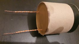
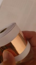
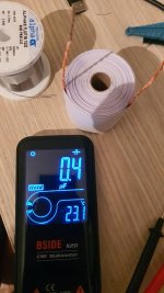
Hi. After a long time of job "grinding", i finally have some time for myself. So next to some serious projects (amp, speakers), i have went on to create something i wanted to do for a long time, and make pio capacitor. Had 20m of copper 0.05mm foil laying around and i wound myself a 0.4uF cap (pics in attachment), since i have access to both machines that can roll it tight, and vacuum chamber. Vacuumed with mineral oil, and encased in wax. Now i have been told to pay attention to inductance of such a capacitor. I have only connected leads to the ends of both foils (each foil is 10m).

Which leads me to this topic and the question at hand. What is the best way to reduce inductance in such a capacitor? How does duelund and the rest do it? What i have managed to pickup from the videos and photos, they leave extra foil on each side (so conductor/foils are not completely parallel, and one side protrudes from one foil, and the other side protrudes with another foil), and i guess they connect somehow those edges on each side (which can't be seen, but it's my best guess).

Attachments

  • 20220403_212345.jpg
    20220403_212345.jpg
    327.6 KB · Views: 182
  • 20220402_220823.jpg
    20220402_220823.jpg
    221.7 KB · Views: 175
  • 20220402_222845.jpg
    20220402_222845.jpg
    317.3 KB · Views: 180
  • Like
Reactions: JMFahey

Biasing N.E.W. A20.1 class A amplifier

I picked up a N.E.W. class A amplifier that had a decent amount of damage to one of the boards. The actual board and traces were fine, there were just a few components that had become charcoal.

I replaced all of the components that were damaged and measured the components that were near them in circuit (transistors on a curve tracer, caps with a Peak ESR meter, etc) including the four output devices. Excluding the components that were charred everything measured normal. I then powered it up on a variac/DBT starting at about 50V. Got it up to line voltage, 122-124V and it doesn’t seem to really be drawing anyting, 0.02A and I’m guessing that’s from the LED that lights up on the front panel. Fuses are good obviously as the power LED lights up.

Measuring from ground I’ve got a +30Vdc and -30Vdc rail on each board directly from the bridge rectifier. Measuring the 3 pins on each of the outputs to the chassis, each pin has either a +30Vdc or a -30Vdc. Overall it seems to be a fairly simple design. I find it odd that only one board had damage, yet it seems that the entire amplifier is doing nothing. I’ve had this amp in the past and I remember it got quite warm, it’s been plugged in for at least 30 minutes and it’s still dead cold.

I’m hoping to get suggestions. I’ve worked on and have repairs several amplifiers so not a complete novice, but by no means an expert either. I have many tools and am competent enough that I should be able to do what is asked of me.

What is the best way of biasing a class A amplifier? Generally with A/B I’ll measure across the emitter resistors and set to a certain voltage (mV) if there isn’t available factory instruction.


Thank you,
Dan

Attachments

  • A41D7A23-38A1-472C-AC67-4BBBAA680692.jpg
    A41D7A23-38A1-472C-AC67-4BBBAA680692.jpg
    989.5 KB · Views: 749
  • D7FF1260-E9BC-48E1-8EFC-F15806FB13E6.jpg
    D7FF1260-E9BC-48E1-8EFC-F15806FB13E6.jpg
    1,010.2 KB · Views: 650

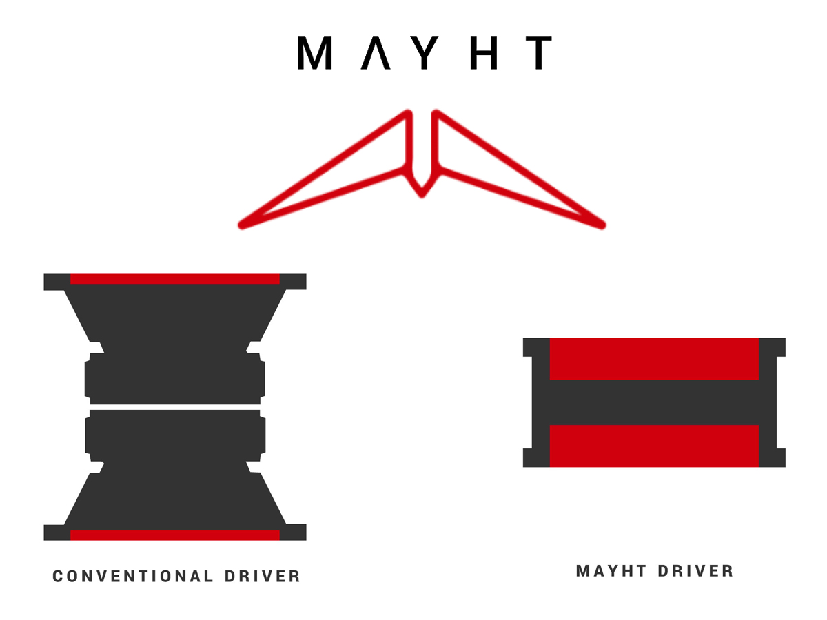
Mayht speaker driver technology

Mayht New Speaker Driver Technology Attracts Multi-Million Investment | audioXpress

“Our vision is that Mayht will become the new industry standard for speaker driver technology”, says Mattias Scheek, CEO of the company. “The world will get used to - until now unimaginable - high-quality full range sound experiences including the full bass spectrum, from the most compact of form factors.”

We are in the process of developing our Technology Platform which will bring optimal sound quality to any device in all verticals. We are in close contact with the world leading Tech- and Audio companies, and see their interest grow at every step that we take”. Driver technology has so far remained unchanged for at least 75 years. With Mayht it is finally possible to think of radically new and smaller form factors, with immense sound quality improvements - a true paradigm shift. Phones will sound like bluetooth speakers, small bluetooth speakers will sound like hi-fi speakers, a flat TV will finally have home-theater sound capabilities.

Mayht – Disruptive Transducer Technology

- So it is a double opposing diaphragm bipole system, pumping air in-between with high excursion. A woofer really, they don't say how high it can go.

20200415185817_Mayht-excursion-to-depthFrontWeb.jpg

Subwoofer Group Delay

Hi guys, after building TQWP, bassreflex and closed cabinets in hornresp, I met delayed bass. According to Aldoshina's researching in 1985, there is acceptable Group Delay values that human ear can't detect: 40-80 hz: 15 ms 80-160 hz: 3 ms 160-1 KHz: 2.5 ms >1 KHz: 1.5 ms What do you think about value - can we increase 40-80 hz range up to 25 ms without blurred, trailing bass? Or there is another factors of delayed bass...?

Inductance used in Push-Pull Output transformer for LTspice Modeling

Since inductance varied with voltage and frequency what Primary and secondary inductance should be used in LTspice modeling for tube amplifier?
I saw some Hammond model specified Primary and secondary inductance at 50/60Hz and some are at 1Khz.
My output tranny (not Hammond) Primary inductance is specified as follow at 1mW : 160-350 H at 50Hz. and 125 Ohms for Primary P-P resistance. That's all parameters I have.
Not really sure what Inductance value I should use for modeling. Also at what frequency and voltage would be more optimal in modeling output transformer inductance?

Thanks in advance.

For Sale Two Jensen line input transformers.

https://www.jensen-transformers.com/wp-content/uploads/2014/08/jt-11p-1bn.pdf
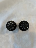
Two ‘octal’ Jensen line input balancing transformers JT11P-1BN. In the 8 pin octal format. New, never used. $45.00 ea. I’ll pay shipping, FedEx ground w/track USA only.

Attachments

  • EE7D3974-3B14-4F8B-954C-39773922CD1B.jpeg
    EE7D3974-3B14-4F8B-954C-39773922CD1B.jpeg
    284.8 KB · Views: 130
  • D479071D-E71B-4730-A634-FF74DC90DBA7.jpeg
    D479071D-E71B-4730-A634-FF74DC90DBA7.jpeg
    442.1 KB · Views: 139
  • 74A5D238-27AC-430B-9391-1B203EB25318.png
    74A5D238-27AC-430B-9391-1B203EB25318.png
    468.8 KB · Views: 137

Is too simple to be true?

I want to try this just for the fun of it. I recently acquired a Tannoy SFX 5.1 sub (horrible thing). I sold the plate-amp, the driver, and remarkably the feet on Ebay. I was about to throw away the empty box out when a question arose . . .

The sub had an 8" down-firing driver which would now be on the floor because I sold the feet. Ignore the measurements because I haven't yet done the math but if I attached a partial 'picture frame' around the base using 25x25mm timber around the side and rear elevations would I have effectively created a 6th-order bandpass sub? In this instance gap between the sub and the carpet creating and additional chamber?

Citronic PPX900 bias problem. Please help!

Hi,
I recently bought a Citronic PPX900 power amp and all seemed fine when I tested it at the guy's place. However, when I got it home and ran it for a while with the lid off I noticed some strange behaviour. Regardless of signal going in or loads connected both heatsinks (top & bottom) seem to heat up fairly quickly. Within two minutes the fan kicks in which means the heatsinks are at approx. 60 degrees C. I then checked all the usual faults like DC on the outputs or bad supply rails etc and found nothing a miss. I then thought maybe the bias might be set way too high but the bias pots still have the red factory seal on them COMPLETELY untouched.

With a signal and speakers connected the amp seems to run ok with no distortion but I haven't had a chance to run it at full tilt yet (I share a house) to see if the shut-off thermal switches trip out. It still gets just as hot though. A thing that really surprised me with this amp when I first connected speakers to it though was the extreme lack of background noise from the speakers when idle. I see that there is a muting circuit in the design but I didn't think it could be this effective! Maybe this could explain some of my biasing problem???

After getting the schematic (from one of Jan Dupont's posts. Thanks Jan!) I was hoping to see some info on biasing guidelines but there was none. I also got the user manual but as you'd expect there's no info in that either on biasing.

The first question would be DO these amps generally run fairly hot when idle???

The second question would be HOW do you set the bias???

I really don't wanna rely on this amp for a gig and then see it blow up while I'm playing!

:hot:

If any of you guys have ANY info that you think would be of help it would be REALLY appreciated! I'd bring it straight back to the guy and get my 120 euro back but he's the other side of the country and it is technically working fine in his eyes.

Thanks in advance!!

Vinny

I've got an old Bash300 plate amp, whooshing white noise

it's been making this quiet whooshing noise. It still works fine, but makes this white noise while in standby and it's driving me bonkers. Is it something I should even bother trying to fix? (having no idea and will simply post loads of pictures to these forums and beg for help) Or just replace the thing? The GAIN knob does not change the volume of the white noise, but as I turn it way up and way down, the sound sorta modulates a bit. I'll attach a sound file here, for what what's worth.
https://drive.google.com/file/d/1yZrh4BZp1HstWJ0ebA3WadXVRdxIhQWI/view?usp=sharing

Looks like about $220 on parts-express or eBay.
Dayton Audio 250 about $160.

Maybe just replace the thing....

BG20 Horn Project

Hi all,

I have decide to make my first project. I choose full range speakers for easy connection purpose. No problem with crossovers etc. I have purchase two Visaton BG20 and waiting now for delivery. Two similar project I found online, both are horn/tube style.
I do not have accurate saw to cut board with necessary precision so need to buy with cut service, most probably from B&Q (I live in UK). Material will be plywood 18mm.
bg20.jpeg
bg20.2.jpeg

Active Crossover Help Needed

I FINALLY found an Altec 808-8a to complete parts needed for a 2 way speaker build with LF woofers and 811b horns. It's been years waiting for a reasonable price on one of these. Just need to build the cab and crossover.

I am looking into using an active crossover to determine the best XO point and then build up the crossovers. Looking at the Behringer CX3400 as I have seen many others have used this kit to good effect. but I am wondering how I am hooking this up to the amps with only balanced XLR connections?

What is the best way to connect an active XO to 2 amps biamping the highs and lows?

Static issues on Interface+Monitors system

Hello,

I have inherited a sound system – two monitors (Mackie HR824mkI) and a Motu 828mkII.
The previous owner ran the system off Firewire but I will not be able to do the same so have been trying to find another way, only interested in getting music output for now. After a couple of hours of tinkering I’ve connected my PC over optical/Toslink and managed to route a sound signal to the main outs, so I’ve got sound! However I have some problems as follows:

1. There is a very(very) slight static during playback
2. After sound has stopped(music ends, paused, etc.) there is quite heavy static that plays for around 5 seconds and then stops.

During troubleshooting I noticed that if I play music that is stored locally(not streaming) problem 2 is solved, although problem 1 is still present. My PC is plugged in over LAN, would there perhaps be interference here?

After some research I’ve tried(to the best of my understanding) to prevent a ground loop by running all the equipment off the same socket. If it’s relevant it's also plugged in to an 'ELC black box' which is how it was previously set up.

Sadly the previous owner passed away, and therefore I don't have much help during setup, which is why I came here. Please guide me if I have not posted this in the correct sub or have not given enough relevant info.

Thank you!

SSE Left channel cutting out

On my SSE sometimes (randomly) the left channel will stop working and the right will simultaneously get weak/thin.

Turning it off and on again resolves the issue. Oddly enough if I turn it off with the music still playing both speakers start playing again as soon as a flip the switch OFF and then gradually fade together as it powers down.

No pops or thumps. Board seems fine.

Any tips on where to look?

saturation of a small transformer

Hello, I am making a preamp of a Marshall JCM800, but i have some questions , I was reading that the Marshall output transformers are smaller than they should and go into saturation to help distortion, I got some small audio transformers from 2.5k to 8 ohms,
these:

1650250019520.png

my idea is to make a 250v preamp pedal and use the transformer as if it were an output but with a 12ax7 and make it go into saturation so that the preamp has the sound of a jcm800 preamp with the saturation of the output transformer but without the power tubes, all in one pedal
My questions are, can I use it as a 12ax7 output transformer? How can I make this little transformer go into saturation? Does it really make a difference to have the transformer saturated?

FS Various pcb boards for sale

Most likely I 9won't be starting any projects with the following boards so here they are for sale.
I'll add some more when I dig up what I have in my stack
Price per piece, I might have multiple of these

All are new and unused.

Amp Control 6 (21st century protection of VZaudio) - 11 euros

Legato 2 (Twisted Pear) - SOLD
AD815 preamp board (PFM) - SOLD
Twisted Pear OTTO II (full kit) - SOLD
Salas UltraBIB positive shunt regulator - SOLD
Cheapomodo (cheap version of Quasimodo) - SOLD
I2S Widget - SOLD

Paypal for friends
Can post international with tracking number

Attachments

  • various_pcbs.JPG
    various_pcbs.JPG
    503.1 KB · Views: 177

Why do BLH's go lower when used together?

Hi,

So this question is really about tapped vs BLH/FLH. I've read in many places that an advantage of using BLH's for a large sound system is that when using multiple in a stack, let's say 4 they work together to reach a lower frequency range. So say you have a BLH horn with Fs of 35, if you put 2-4 of these together you could feasible reach an Fs of 30Hz or lower. However tapped horns wont do this. The addition of multiple tapped horns will give you a great SPL but no more low end or Fs.

I haven't been able to find an explanation as to why this is, I've only ever read it stated as fact. So is there anybody that could offer an explanation or point me in the direction of one? I'm interested to know why!

Much appreciated.
Thanks

Small cheap ripole subwoofer

I want to build a small ripole subwoofer for my office. I had one here for a few days, the classic one with the SLS12 driver and it suited the room very well (not very well acousticly, small and with neighbours). I could get a lot of good quality bass from little power from them without disturbing the neighbours. I was amped with a seperate custom amp (don't know what it was) with dsp build in wit a line out to my amplifier that power the main speakers (small fullrange bookshelfs). The Ripole did nt load the room but gave a very nice low bass. Even in the toilet next to the room i could not hear it (with only a thin but isolated drywall in between). So it looks like the perfect solution for the bass issue i have here.

As the SLS12 already wen way to loud, i'm looking for cheap smaller drivers to use, and came to the GRS 10SW-4, with decent xmax (8.5mm), a relative high qts (0.64) and not to low fs (34Hz). It looks like a perfect cheap candidate for it. I did see how Jazzman designed it and it looks like it could work in a fairly small package sitting under my desk, even with 2 drivers. I'm just thinking on what wood to use. Does this have the same needs as a boxed speaker, or can i use any wood like with OB as long as it's stiff and non resonant? For amping i'm thinking about an icepower module, and i will use dsp anyway on this setup as i'm also want to build monitor-like multiways that will use dsp.

So my question is, is the driver ok for this and what cheap wood would you suggest (birch plywood is ridiculous expensive now down here so last option now).

WTD: Specific phono ground post / terminal, picture in pisting

The title says it, I’m searching for a specific phono ground connector with a M3 thread for fixation on the terminal plate, I‘m searching this specific model for a restoration, Sony used these ground posts on their HA-55 head amp and on the PS-X9 turntable, Sun Audio (Uchida) use them on some of their power amps, so these ground posts or very similar ones must be in production for decades…

Any offer or any hint regarding a distributor to source them would be very appreciated…
A14A5E3A-5086-435E-AF9F-4D6BB8562558.jpeg


Best regards

Michael

WHAMMY - Grounding

Hi folks, I am at the point where I am wiring the input/outputs of the WHAMMY. I have the WHAMMY chassis that comes with the full kit. I removed the anodized finish where the six chassis plates meet, around the chassis ground screw, and where the volume pot meets the chassis.

Question: Do I need to ground the pcb to the chassis? If so, can I do it by removing the anodized finish where the stand-offs that hold the pcb pass through the chassis?

Many thanks,

John

Bluetooth Amplifier Module BM64 confusion

Hi All,

I have been developing a Bluetooth Amplifier board and have come across an issue. The BT audio module I was intending on using (BM64) has a pin out for right channel out (AOHPR) and a left channel out (AOHPL) which is odd as most BT audio modules have 4 pins a L-, L+, R-, R+. What would be the negative inputs in the case of the BM64 be. The datasheet is unclear. It seems that maybe AOHPM could provide ground for both but I thought the negatives were normally kept separate for each channel.

You may ask why use this module at all then but it offers BT 5.0, relatively easy programmable control and an aux in input. Unless anyone knows one similar with L-, L+, R-, R+ output pins.

Anyway here's the datasheet: http://ww1.microchip.com/downloads/...tereo-Audio-Module-Data-Sheet-DS60001403E.pdf

Any help on this would be much appreciated.

Thanks all!

Jonny

6K6 SE guitar amp, heater question

Hi, I'm starting to build a 12AX7-6K6 SE amp with EZ81 rectifier and my question is about the heaters.

I have two 230V-11.6V 14A toroids which I'm planning to use back to back and get the heater voltages from the 11.6V of the first transformer and B+ from the 230V of the second transformer. The issue is that the 6K6 has 6.3V 0.4A heaters and the EZ81 has 6.3V 1A heaters so I just can't connect them in series to get the heater voltages. Should I just use dropping resistors?

Resistor calc:R=V/I
6K6 11.6V to 6.3V at 0.4A = ~12R 5W-10W
EZ81 11.6V to 6.3V at 1A = ~4.7R 10W or more

OR should I add there 6V fixed voltage regulators? Or do you know any other Full Wave Rectifier tube with separate heaters at 0.4A?

-Pete

For Sale Selling 4 separate types on input/output terminals for diy.1) White band#3, insulated internally and externally. Quantity of 12.2) Red band #1. Ins

Selling 4 separate types on input/output terminals for diy.
  • White band#3, insulated internally and externally. Quantity of 12.
  • Red band #1. Insulated internally and externally. Quantity of 10.
  • Red band #2. Insulated internally and externally. Quantity of 12.
  • Black band #4 Insulated internally and externally. Quantity of 10.
Fifty five dollars, shipping included.

Using Toroidal PTs as tube OTs - methods and sources

Hello all --

I am trying to get my arms around using Toroidal dual pri/dual sec type power transformers as OTs for tube amps. Here are the main questions I have:

1. How do you figure out which primary/secondary values you need? How do VA ratings for the xfmr translate to wattage? Are there formuli or decoder rings somewhere?

2. What topologies are best suited for these xfmrs? Any tricks to broaden frequency response?

3. What are some good USA toroid suppliers? Shipping costs for European suppliers are BRUTAL. I am aware of Antek - but they do not offer PTs (>25VA and <300VA) with the specs you most often seen mentioned as usable (115v/115v/6v/6v, 115v115v/18v/18v). Antek offers a full line of PTs with 12v secondaries -- could these be used?? which VA ratings are usable??

I have looked around in several threads but have not found definitive info - I am hoping to pull this info into a single thread so it is useful to the community at large. Thanks for the help!!!!

High-Performance USB SPDIF Converters (CONUS)

I have a few usb to spdif converters, I don't really use them anymore so I figured someone here could give them a good home.
  • Legato II: Serviced by Jocko Homo himself a few years back (RIP). I'm sure everyone's familiar with his reputation for measuring phase-noise etc. Been using it with the Segue DAC he designed. Battery-powered, will include the charger and the cable he made for it. I think somewhere around 375 is appropriate.
  • Gordon Rankin's Wavelink-HS. Supports up to 192k on paper but I can't test/verify this high rate myself at the moment. Because of this I'll knock the price down to 300.
I'm open to negotiation, I know these are good units and I just want them to see some use.

I'll upload pictures ASAP, thanks for looking.

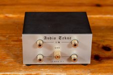
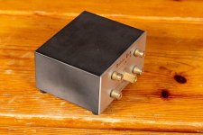
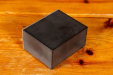
Audio Tekne LT-8310 CD player interface

Audio Tekne LT-8310 CD player interface. Carbon block body and super permalloy transformers. Interposed between CD player and preamplifier or integrated amplifier, it greatly attenuates noise and distortion typical of digital sources, bringing substantial benefits in terms of intertransient silence and dynamics. €.510

Attachments

  • audiotekne05305-01-2022.jpg
    audiotekne05305-01-2022.jpg
    145.6 KB · Views: 150
  • audiotekne05405-01-2022.jpg
    audiotekne05405-01-2022.jpg
    155.2 KB · Views: 151
  • audiotekne05505-01-2022.jpg
    audiotekne05505-01-2022.jpg
    101.4 KB · Views: 137

DSD not functioning properly with new 9038 installation

So after some pondering I replaced my 9018 board with the 9038. I already had the Mercury. It was a matter of changing the 4 resistors.

With the 9018 I could listen to DSD thru the JLSounds i2soverusb V3 card and Audirvana Studio
in my computer. I even got the latest JLSounds software installed.

But I have not been able to make it function with DSD. There is very loud intermittent swoshing sound every 5 seconds or so. There is music reproduction btw. I ordered some ufl cables to see if connecting the 2 boards with these the issue is resolved. The connections between both boards are exactly the same as with the 9018. 4”.

I’ve read about the issue here without any clear explanation to me. Once the topic of the SW 2 and the switch positions come on, I get lost, b1110 d16, etc. It looks like it does not have anything to do with Audirvana, like I said it worked with th 9018. I’ve tried all the DSD settings in Audirvana with same results.

If someone has solved the DSD issue here with the 9038 I would appreciate a pointer. Thanks!

Trouble finding spare capacitors

Hi.
I’ve just acquired a couple of Whatfedale DX-2 Satellite speakers for my surround sound system.

After wiring them in to my system and finding that they didn’t work, I decided to take them apart to see what the issue was.

Turns out, whoever had them before I acquired them had obviously turned them up too high, and had blown a capacitor in both speakers.

I’ve included a picture of the capacitor in question. I cannot seem to find one anywhere to be able to them.

Any help would be greatly appreciated.

Thanks in advance.

AshB123

A2C5B5A3-C265-4C0C-9CE1-FE99F5060530.jpeg

DIY TPA3116D2 Amp with Charging

Well thanks to everyone who helped me out on this forum when I was designing this board! Took me a long time to get it to this point but I have a few made now and have been happy with the results - currently using one in my Fidelity speaker. It uses the TPA3116D2 chip from Texas Instruments and has a TI battery charger chip which handles charging of a 3S Li-Ion pack. I'm using a relatively outdated RN-52 for the Bluetooth but I liked it for its differential outputs and programmability. I may update it down the line. There's also connections for media controls which I'm using with a custom touch control board on my speaker. The key for me was having a compact package I can use in lots of projects. I made the first prototype at home after getting a board printed using a hot air gun and stencil. Since then I've bought them assembled as making them is a long (but otherwise therapeutic) process.

I've made a video on how I designed it and the board layout here: Login to view embedded media I've also linked my final schematic, BOM, and all the helpful learning docs I acquired on the way on my plans page here: https://www.jcracoustics.co.uk/plans/

TLDR Lessons learned in this process:
  • Aluminium Polymer Capacitors are VERY expensive and I probably should have just used Electrolytic for my Bulk Capacitors but I really was sparing no expense on this board.
  • Layout is everything when it comes to current sensing resistors (charging on my first prototypes didn't work as my grounding and layout wasn't right)
  • Start small - I spent ages getting bogged down in how to do an active crossover with split rails before I finally decided to leave it out on this design. This also gave me more flexibility on using the amp in different projects this way.
  • Black PCBs look great but get your first prototype in green because it's a million times easier to see the traces when you're debugging.

Thanks again to everyone on here who gave me a hand. I linked the forum in my video description since this is the best resource for those looking to do the same. Hope the resources and video help anyone who wants to try and make a similar design but if you want any more info then give me a shout here.

FYI - I'm not a company although I have made a swanky website for all my designs. I do technically have a spare of this board to sell but frankly even at cost it comes out expensive (I think board design has to be a labour of love unless you can afford to produce millions at a time!)

Attachments

  • PCB.png
    PCB.png
    850.2 KB · Views: 137
  • Spread_Full.jpg
    Spread_Full.jpg
    266.5 KB · Views: 134
  • fidelity_build-02.jpg
    fidelity_build-02.jpg
    119.8 KB · Views: 132
  • fidelity_build-07.jpg
    fidelity_build-07.jpg
    81.1 KB · Views: 135
  • fidelity_build-05.jpg
    fidelity_build-05.jpg
    141.3 KB · Views: 130
  • Like
Reactions: aditya and stv

changing the mdp in the moode audio to support sacd-iso format of music files

hi there,
so far moode has been updated to version 8.02 and it works great . thank you Tim.(who creates moode)
but i want to ask for help from you guys who knows the linux computing lanagues.
so i think you might be kind enough to help me out with your ability and knowledges.

i love to use music format of the sacd-iso which is originated DSD files . it is large in file, but originated from the SACD.
and Tim (owner of moode) refused to add sacd-iso mdp into the moode source becaue he think the sacd-iso is not updated from time to time.
the official mdp source is made by MAX keller mann in below link:
https://github.com/MaxKellermann/MPD

but i do know that there is a man who is updating the un-official MPD file with the sacd-iso in below link by ManIsiutkin who is also the same writher for the sacd-iso decoder for foobar, of which works great and world know. this is the source for his work:
http://git.musicpd.org/cgit/manisiutkin/mpd.git

so i ask for help that would you help to teach me or post how to update (or replace) the existing mdp in Moode (any version will be fine) and since i am a noobie in linux lanuages, so a detail tutorial of post iwll be very kind of you.
i know it is an unreasonable request but just want to check if you can help.
thanks
by chaos. 23333.
thanks

PS Audio 100 Delta

Hi everyone,

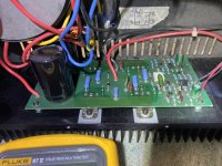
I'm really stuck on this PS Audio and hoping someone can help. I cannot find any schematic information online, so i feel a bit blind. This amp had stopped outputting on the left channel, it just had a loud buzz. If left on long enough, a burning smell would gradually occur. I opened it up and checked the main transistors which are screwed onto the massive heatsink at the back of the unit. One of them - a A1360 was shorted on the left channel. I ordered a replacement online and fitted it. Then, I turned it on while connected to my dim bulb tester. Everything came on fine, and no smoking. I then tested both sides of the unit. When plugging the speaker into the right side - the dim bulb didn't really light up at all and sound worked great. When plugging into the left side, the bulb lit up a bit and a loud hum was heard initially (2 seconds) and then it faded away and the sound worked perfectly. The following day I tested it again and this time (with the speaker cables plugged into the left side) as soon as i turned it on the dim bulb lit up and stayed lit, and I saw an area of the board light up and smoke came out of it. I quickly turned it off. I couldn't see any burned components, but there was a burnt bit of the board around another A1360 in the left channel (top middle of the board). Unfortunately none of the components are marked with component numbers on the board. So - once again I took the board off and replaced this A1360 (it wasn't shorted, but i replaced it anyways to be safe). Turned the unit on again, this time with no speakers connected and did what I should have done after the first A1360 replacement - I checked the speaker outputs for DC offset. turns out the left side has 1.7vdc on the outputs.

Since this discovery, I have checked all transistors on the left side for shorts or partial shorts, as well as the large capacitors for shorts and capacitance readouts. I don't really know what else to do in trying to find the fault when i have no schematic information available. Can anyone help? I recognise it might be impossible. I've attached some photos of the board anyways. The red circled component is the first one which was shorted and replaced, the yellow circled component is the one i saw burn up a bit (but didn't appear to be shorted) it was also replaced.

Thanks!

IMG_5094.jpg

Attachments

  • IMG_5093.jpg
    IMG_5093.jpg
    486 KB · Views: 162
  • IMG_5091.jpg
    IMG_5091.jpg
    555.5 KB · Views: 160

Sublime Acoustic K231 opinion

Hi all,

Since my actual crossover - a good sounding cheap device from China - has proven very susceptible to RFI ingress, I'm considering buying the K231 from Sublime Acoustic.

However, besides the 8 reviews on the company website I cannot find any real world review.

I've also emailed them and didn't get any reply, which I find disturbing.

I would like to get some feedback from eventual users, specially regarding sound quality and absence of noise (I use horns, any noise in the chain is amplified and unbearable) but also regarding Sublime Acoustic as a company and eventual after-sales service.

Tr tester circuit idea with constant Emitter Current

To match Transistors in Hfe under similar condition to the usage in the amplifier, with up to 0.1 A of Ic, I found that I can't rely on cheap Hfe testers with limited current. I googled and found several easy ways to measure Transistor's Hfe. I was about to start with very simple circuit using only two resisters like this. This should be sufficient for my purpose of Hfe matching, but I thought I could make it a little better.
https://userdisk.webry.biglobe.ne.jp/013/879/50/N000/000/005/135210744168713231203_Tr_hfe_measurement.GIF

While reading some articles, I learned that it's better to compare Transistors with constant Collector current to be more accurate. Since it's not easy (I don't know how yet) to make the Collector current constant, many people designed constant Emitter current circuit to test Tr and some named them "constant Collector current". I found some circuit designs using Zener Di as the source of constant voltage. Looks better.
Transistor Tester to test Hfe and working of NPN and PNP Transistors

I ran some LTSpice simulation and could never exclude temp dependency of Zener and DUT's Vbe even with compensation by attached Di. Then I found idea to use external fixed voltage source instead of Zener Di. Looks good. As many of you, I have a DC power supply box with so-so good stability. Why do we have to create "constant DC voltage source" inside of Hfe tester? So I put many parts on the circuit board in referring to this web page. I have many old OPamp, Trs, R, C in my box. I don't need to be afraid of complexity of the circuit. Including voltage splitter and 3 relays for NPN/PNP switching and Tr/FET switching made the board full, as attached picture.
Project 177

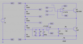
After that, I recognized that still I can't be free from the influence of DUT's Vbe variation and temperature dependency. Then I found a smart idea to include DUT inside of the OPamp's Feedback loop. It achieves absolutely constant voltage on Re so that constant Ie can be realized. Also now the circuit became much simpler than before.
トランジスタ、FET選別アダプタ

And I hired one demand: variation of the measurement voltage in addition to the variation of the emitter current. Please see attached LT Spice screenshot. Now I can check Tr Hfe with 1, 3 and 6 volt on DUT. Emitter current can be set to any value by Re adjustment for 4V of VRe. PNP/NPN switching can be done by swapping VCC/VEE connection to the circuit and switching voltage controlling Tr between 2SC/2SA. I can use this to measure Vgs of FET with constant Source current, too. If I want to measure with pulse current to avoid heating up DUT, probably I can add PWM circuit to U1 OPamp input.

TBH I can't design a new circuit at all. All what I did was just copy and paste from existing circuits on web. So I'm not sure if this really works. It seems working at least on LTSpice. So your review of attached LTSpice screenshot is appreciated. If you find any critical mistakes, I'd happy to hear it. Thanks.

Attachments

  • IMG_1483.JPG
    IMG_1483.JPG
    250.8 KB · Views: 255
  • LTSpice_Screenshot_Hfe_Tester.png
    LTSpice_Screenshot_Hfe_Tester.png
    66 KB · Views: 267

Keep the bug screen!

I have a pair of DE120s and noticed one of the gaskets was slightly off center, covering the very edge of the mouth of the CD. So I peeled it off to re-center it. Turns out the bug screen is held in place by the gasket, so the screen came off with it. Since the screen was off I thought I might as well take this opportunity to test with vs without. Glad I did, because I had always thought the screen was just for bugs, but it appears to help quite a bit. Very likely an important part of the driver design. The screen was off for the first sweep, then I placed it on being careful not to move the driver between tests.

1327DAA3-C7F4-4113-B048-F279F989DBD5.jpeg


Red = no screen
Blue = with screen

Donor amp Power Supply for ACA (Center tapped trafo question)

Hi All,
Pardon the newb question. I have googled this to death and cannot find a straight answer. I would like to build an ACA using a Hafler P1500 as a donor chassis and start of a power supply. The transformers in the Hafler appear to be high quality, and I'd really like to be able to use them for a premium ACA build. The transformers have dual CT windings (40-0-40 and 80-0-80). I've read that you can wire the windings of some transformers in series to double the current and keep the voltage the same. Essentially, I'm looking for a way to use the 40-0-40 winding to produce 20VAC leading to 24vdc for the ACA boards. I had planned on using SLB single rail power supply boards to power the ACA boards in a true dual mono setup. Can someone explain in elementary school terms the simplest way for me to achieve 24vdc with these trannies? Thank you all! --Jaybird

Attachments

  • IMG_7611.jpg
    IMG_7611.jpg
    923.6 KB · Views: 210
  • IMG_7612.jpg
    IMG_7612.jpg
    472.4 KB · Views: 139

Preamplifier gain stages

Hi

I am quite new to electronics and have built few amps before (not my own design). Now I am trying to design my own preamplifier but there are so many ways to create one that I haven't gotten that far.

I am using my cellphone and computer as music source most of the time but I also listen to vinyl records so the preamplifier will need to have quite a lot of voltage gain. I will later build a riaa amplifier so no need to worry about that yet. I want to use discrete transistors because I want to learn precisely how amplifiers work and also be able to be in control of more things.

So far I have gotten best results with 2-stage bjt amplifier where the input stage is common emitter which amplify the voltage and the second stage is common collector aka buffer amplifier which lowers the output impedance. Then I also added a feedback which I adjust to set the output voltage. I got enough voltage gain and THD values of about 0.1% on line level 750mV.

I have also tried cascade in the first stage and common collector on the second stage. Cascade made good frequency response but it had too much voltage gain and I didn't manage to make working feedback to it. The THD was also around >1% on line level which is way worse than the 2 stage bjt amp that I tried. The cascade was made with fet transistors.

So my question is which gain configurations/stages should I use to get lower THD values and also as flat frequency response as possible. You can also just name some different gain stages / transistor configurations which could work as an amplifier. Thank you for your responses!

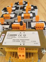
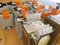
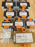
NORATEL ISOLATING TRANSFORMERS

Safety Isolating Transformers (SU and FR series) FR series is very popular these days designed for installation in processing industry & switchboards..
We have FR60B, FR78B and FR84B supplied on request for custom designs...
Comes with a separate insulated windings, moulded in self-extinguishing poly-urethane and capsulated in plastic.. Simple assembly in cabinets or switchboards...
Enquire now! cpg@rfwaves.com.au / 0406288952

Attachments

  • 20220418_100834.jpg
    20220418_100834.jpg
    390.6 KB · Views: 117
  • 20220418_100937.jpg
    20220418_100937.jpg
    518.8 KB · Views: 118
  • 20220418_101139.jpg
    20220418_101139.jpg
    353.9 KB · Views: 116
  • 20220418_101240.jpg
    20220418_101240.jpg
    499.5 KB · Views: 113
  • 20220418_101743.jpg
    20220418_101743.jpg
    330.2 KB · Views: 124

STUDIO 350 PAIR

This listing is for a PAIR of famous silicon chip studio Power amplifier fully build and tested !

We re-design the PCB with extra ground to give that added effect
PCB size 240mm X 100mm, Thickness 1.6mm with Gold / Black under - surface finishing

All mounted components from reputed Electronics suppliers Mouser, Digi-key and Element-14. Resistors / capacitors used are military grade Low-noise DALE

We use CONRAD heat sinks with a Neat finish
Tested and Bias with Rail voltage /- 70
world wide shipping available

If 1 Kv transformer needed to be built for your stereo that can be done for an extra cost. Enquiries - cpg@rfwaves.com.au / 0406288952

Attachments

  • 20220418_155555 n.jpg
    20220418_155555 n.jpg
    378.1 KB · Views: 136
  • 20220418_155626.jpg
    20220418_155626.jpg
    406.1 KB · Views: 121
  • 20220418_155642.jpg
    20220418_155642.jpg
    365.1 KB · Views: 121
  • 20220418_155714.jpg
    20220418_155714.jpg
    324.9 KB · Views: 113
  • 20220418_155746.jpg
    20220418_155746.jpg
    303 KB · Views: 122

Musical Fidelity Digilog Dac

Hello All,
I have just bought a Musical Fidelity Digilog Dac which I intend to modify. I need some help as there is a previous repair which is not as good as I would like.🙁
Firstly does anyone have the circuit diagram/service manual?

If not would someone with one of these units be able to tell me the value of the following components: transistor TR8, resistor R46 and resistor R47 (near -15volts adjusting pot ) these have been replaced in my dac but not with the same type as the factory.

There is also a modification on the board, (near the sony receiver) R20 has 2 resistors a 15Kohm and a 4.71Kohm with a 330uF/63v capacitor from their midpoint to TR4 is this a factory modification?

I have attached some photos which may help.
Thank you in advance for any help

Attachments

  • IMG_0072.JPG
    IMG_0072.JPG
    696.8 KB · Views: 1,141
  • IMG_0071.JPG
    IMG_0071.JPG
    750.6 KB · Views: 1,425

Apocalypse AAB-2900.1D/Sound Digital 3000.1 rebuild

Apocalypse AAB-2900.1D same as Sound Digital 3000.1evo.

I've cleaned up everything, new ps gate resistors and mosfets. I do have switching pulses.

There are 2 rectifier diodes - S1 and S2. One of them is dead short across all pins - S1. S2 is OK. Is S2 = MBR40250TG or MUR1620CTG ? So S1 would be his counterpart ?

Do I need Positive Common Cathode + Negative Common Anode rectifier ? As this is only a positive +rail amp, shouldn't be S1 the same as S2 ?

I've tried to power up the amp with just the healthy one, but with no avail. The 3 indicators are being light up, the power one cycles, as the amp tries to run but no rail voltage is being build. I think I need both of the rectifiers.

Attachments

  • 1.jpg
    1.jpg
    135.6 KB · Views: 252
  • 2.jpg
    2.jpg
    106.9 KB · Views: 211
  • 3.jpg
    3.jpg
    101.8 KB · Views: 218
  • 4.jpg
    4.jpg
    131.6 KB · Views: 233
  • 5.jpg
    5.jpg
    133.4 KB · Views: 236

Need modifications for quasi complementary output stage

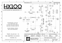
Helo all my dear friends again I need your Lil bit help here. Recently I built a amp from this schematic it sounds well but I wanted to change its output to quasi complementary output stage..
Bcoz quasi output stage gives deep bass and good sound quality. I am not so good in modifying circuits. I just build using schematics only. So I hope any one can guide me or modify this schematic for me. Here is a schematic..
Many thanks in advance.🙂

Attachments

  • Hx100 100watt Amplifier Circuit Diagram V3.1.PNG
    Hx100 100watt Amplifier Circuit Diagram V3.1.PNG
    397.8 KB · Views: 737

Hum noise on pre amp vintage

[Solved] Hum noise on pre amp vintage

Hi DIYers!


I upgraded an 80's receiver, which has the obsolete SANKEN SI1340H in the outputs.

I put a pair of APEX AX14 in its place and the sound is fantastic! However, the "hum" is very evident when there is no sound. There is no difference in changing the volume control, only when the bass control increases. It uses the HITACHI HA1457 as pre amp.

At first, it looks like a ground loop. So I refined and improved the star grounding.
I replaced some pre-amp and power supply electrolytes, but "hum" remains. 😡
I imagine that this HA1457 pre amp has a high output (gain) level. I would like to know how to lower the HA1457 gain or other more appropriate solution.


Thanks for all the help and sorry for my bad English! 😀

Edit:
[Solved]
I decrease the APEX AX14 gain: I changed the R8 resistor value from 560R to 1K. All the noise disappeared. 😀😎

Attachments

Large transformer build ...., simple voltage regulation advice needed

Hello , I am currently building transformer for powering car amplifiers in home . The original plan was to use the transformer unregulated , but the voltage drop under even a small load is unacceptable . The transformer is good for 1750 va . I am hoping to succeed in getting maybe 130 amps at 14 volts with some type of constant voltage / constant current regulation scheme . I thought about multiple off-shelf buck converters in parallel , but I'm finding that unless they are designed for master-slave operation , you cannot accomplish this . The primary is done and the secondary is not because I don't know which voltage to wind for considering the lack of knowledge concerning the best ( and cheapest ) way to realize this . Thanks ahead of time for any good advice .

Attachments

  • 20220409_193418.jpg
    20220409_193418.jpg
    658.4 KB · Views: 155

ULN Voltage regulators >=1.5A

Hello,

I use the well known and ultra low noise voltage regulators TPS7A4701 and TPS7A3301 from Texas Instruments: they are SMD parts and are amongst the best available.
But they are both limited to 1A. In addition, the negative TPS7A3301 is limited to -5V whereas I sometimes need -12V.

Do you know similar very low noise VR that would handle 1.5A, and could deliver up to -12V for the negative version ?

Thank you very much,

Lm317> capmx woes

In renovating the psu for my preamp ive decided to try the cap mx filter post lm317 337 regulation. The gain stage is current hungry class a so the high impedance of the capmx doesnt bother me much.

My question for the moment is what load cap for the lm317 is recommended in this situation. I feel that 317 provides all the lf filtering i need and the capmx is for the hf noise filtering. For that shouldnt the load cap for the 317 337 be 1uf/10uf recommended by the datasheet? How would this affect the input bjt of the capmx? Any stability issues? Would like to know your thoughts. Thanks

A concept for Amigas and Tarkus

For anyone who uses Sketchup. Just a concept. Like most concepts it will remain only that. Aiming for the most seamless monolithic result.

Using standard dimensioned clay chimney liners and 1/4 mild steel to build would be an interesting take on minimalist industrial if you had the tools available.
Impractical. Of course. Just a concept. Obviously much more easily done in MDF. But just knowing they were 1" thick terracotta and you overcame the challenge would be cool.
ABC Black.jpg

Or in natural clay with a clearcote
ABC Natural.jpg


Original Sketchup .skp file for anyone interested in rotating/zooming/reimagining
https://filepost.io/d/2inYPmTn2K
https://filepost.io/d/uGzBqoHRRJ

Questions re: SSE power supply

First post over here...Howdy!...Looking at spending some tax return cash and thinking an SSE amp would be a good place to do that. Looking at KT-88's, as I have a pair of EH from a project that never got off the ground. After checking the chart and seeing 3K loading with about 490 vdc as a value to shoot for, I started playing with PSUD and found that I'd have to use SS rectification with an EDCOR XPWR033...or am I way off base here? If this works I have a bunch of Vishay 1200v 8A HEXFRED's and wondered if anyone has had any issues with those. Thanks in advance.

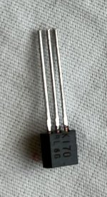
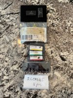
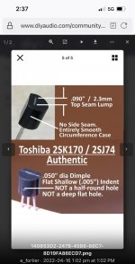
For Sale Multiple DAC and transistor offerings. Many thanks to E_fortier for the help with the illustration showing the validity of the 2SK170 BL!

In order of apperaence -

CS8412-CP 2 total
2SK170 BL 86 total
2SJ184 - 1 total
2SK982 - 1 total
2SK170 GR - 3 total
2SC1845 - 16 total

$110.00 I will cover shipping and send track, FedEx ground.

Attachments

  • 09A040CC-5474-4840-8496-6D7266BBAE3B.jpeg
    09A040CC-5474-4840-8496-6D7266BBAE3B.jpeg
    807.3 KB · Views: 182
  • 47957211-B4B3-4B8B-B15C-9821CE4B4A60.jpeg
    47957211-B4B3-4B8B-B15C-9821CE4B4A60.jpeg
    161.8 KB · Views: 149
Projects by fanatics, for fanatics
Get answers and advice for everyone wanting to learn the art of audio.
Join the Community
507,680
Members
7,883,980
Messages

Filter

Forum Statistics

Threads
406,019
Messages
7,883,980
Members
507,680
Latest member
McCoy22