To match Transistors in Hfe under similar condition to the usage in the amplifier, with up to 0.1 A of Ic, I found that I can't rely on cheap Hfe testers with limited current. I googled and found several easy ways to measure Transistor's Hfe. I was about to start with very simple circuit using only two resisters like this. This should be sufficient for my purpose of Hfe matching, but I thought I could make it a little better.
https://userdisk.webry.biglobe.ne.jp/013/879/50/N000/000/005/135210744168713231203_Tr_hfe_measurement.GIF
While reading some articles, I learned that it's better to compare Transistors with constant Collector current to be more accurate. Since it's not easy (I don't know how yet) to make the Collector current constant, many people designed constant Emitter current circuit to test Tr and some named them "constant Collector current". I found some circuit designs using Zener Di as the source of constant voltage. Looks better.
Transistor Tester to test Hfe and working of NPN and PNP Transistors
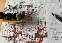
I ran some LTSpice simulation and could never exclude temp dependency of Zener and DUT's Vbe even with compensation by attached Di. Then I found idea to use external fixed voltage source instead of Zener Di. Looks good. As many of you, I have a DC power supply box with so-so good stability. Why do we have to create "constant DC voltage source" inside of Hfe tester? So I put many parts on the circuit board in referring to this web page. I have many old OPamp, Trs, R, C in my box. I don't need to be afraid of complexity of the circuit. Including voltage splitter and 3 relays for NPN/PNP switching and Tr/FET switching made the board full, as attached picture.
Project 177
After that, I recognized that still I can't be free from the influence of DUT's Vbe variation and temperature dependency. Then I found a smart idea to include DUT inside of the OPamp's Feedback loop. It achieves absolutely constant voltage on Re so that constant Ie can be realized. Also now the circuit became much simpler than before.
トランジスタ、FET選別アダプタ
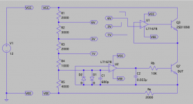
And I hired one demand: variation of the measurement voltage in addition to the variation of the emitter current. Please see attached LT Spice screenshot. Now I can check Tr Hfe with 1, 3 and 6 volt on DUT. Emitter current can be set to any value by Re adjustment for 4V of VRe. PNP/NPN switching can be done by swapping VCC/VEE connection to the circuit and switching voltage controlling Tr between 2SC/2SA. I can use this to measure Vgs of FET with constant Source current, too. If I want to measure with pulse current to avoid heating up DUT, probably I can add PWM circuit to U1 OPamp input.
TBH I can't design a new circuit at all. All what I did was just copy and paste from existing circuits on web. So I'm not sure if this really works. It seems working at least on LTSpice. So your review of attached LTSpice screenshot is appreciated. If you find any critical mistakes, I'd happy to hear it. Thanks.
https://userdisk.webry.biglobe.ne.jp/013/879/50/N000/000/005/135210744168713231203_Tr_hfe_measurement.GIF
While reading some articles, I learned that it's better to compare Transistors with constant Collector current to be more accurate. Since it's not easy (I don't know how yet) to make the Collector current constant, many people designed constant Emitter current circuit to test Tr and some named them "constant Collector current". I found some circuit designs using Zener Di as the source of constant voltage. Looks better.
Transistor Tester to test Hfe and working of NPN and PNP Transistors
I ran some LTSpice simulation and could never exclude temp dependency of Zener and DUT's Vbe even with compensation by attached Di. Then I found idea to use external fixed voltage source instead of Zener Di. Looks good. As many of you, I have a DC power supply box with so-so good stability. Why do we have to create "constant DC voltage source" inside of Hfe tester? So I put many parts on the circuit board in referring to this web page. I have many old OPamp, Trs, R, C in my box. I don't need to be afraid of complexity of the circuit. Including voltage splitter and 3 relays for NPN/PNP switching and Tr/FET switching made the board full, as attached picture.
Project 177
After that, I recognized that still I can't be free from the influence of DUT's Vbe variation and temperature dependency. Then I found a smart idea to include DUT inside of the OPamp's Feedback loop. It achieves absolutely constant voltage on Re so that constant Ie can be realized. Also now the circuit became much simpler than before.
トランジスタ、FET選別アダプタ
And I hired one demand: variation of the measurement voltage in addition to the variation of the emitter current. Please see attached LT Spice screenshot. Now I can check Tr Hfe with 1, 3 and 6 volt on DUT. Emitter current can be set to any value by Re adjustment for 4V of VRe. PNP/NPN switching can be done by swapping VCC/VEE connection to the circuit and switching voltage controlling Tr between 2SC/2SA. I can use this to measure Vgs of FET with constant Source current, too. If I want to measure with pulse current to avoid heating up DUT, probably I can add PWM circuit to U1 OPamp input.
TBH I can't design a new circuit at all. All what I did was just copy and paste from existing circuits on web. So I'm not sure if this really works. It seems working at least on LTSpice. So your review of attached LTSpice screenshot is appreciated. If you find any critical mistakes, I'd happy to hear it. Thanks.
Attachments
Last edited:
I designed my own transistor matcher.
It basically an inverting bipolar or enhancement type mosfet stage.
The base voltage, collector voltage, base current are all measured using differential amplifiers and applied to a PIC32mx as2 array.
The output goes to a PC via USB.
The pc display displays upto 5 transistor curves for comparison.
It can read NPN, PNP, N channel or p channel transistors.
The curves can have pointer run up them to read off base, voltage, collector voltage and Hfe.
I built this tester and have been using it. One critical mistake I found was, unnecessary protection diodes D1&D2. I had to remove them to make this circuit work. After removing them, it worked so-so fine, however still not perfect. On LTSpice simulation, the resulted voltage on the Re was dead flat and matched to the OP-Amp input voltage with far less than 1mV of accuracy. It's not the case on the real tester.To match Transistors in Hfe under similar condition to the usage in the amplifier, with up to 0.1 A of Ic, I found that I can't rely on cheap Hfe testers with limited current. I googled and found several easy ways to measure Transistor's Hfe. I was about to start with very simple circuit using only two resisters like this. This should be sufficient for my purpose of Hfe matching, but I thought I could make it a little better.
https://userdisk.webry.biglobe.ne.j.../135210744168713231203_Tr_hfe_measurement.GIF
While reading some articles, I learned that it's better to compare Transistors with constant Collector current to be more accurate. Since it's not easy (I don't know how yet) to make the Collector current constant, many people designed constant Emitter current circuit to test Tr and some named them "constant Collector current". I found some circuit designs using Zener Di as the source of constant voltage. Looks better.
Transistor Tester to test Hfe and working of NPN and PNP Transistors
I ran some LTSpice simulation and could never exclude temp dependency of Zener and DUT's Vbe even with compensation by attached Di. Then I found idea to use external fixed voltage source instead of Zener Di. Looks good. As many of you, I have a DC power supply box with so-so good stability. Why do we have to create "constant DC voltage source" inside of Hfe tester? So I put many parts on the circuit board in referring to this web page. I have many old OPamp, Trs, R, C in my box. I don't need to be afraid of complexity of the circuit. Including voltage splitter and 3 relays for NPN/PNP switching and Tr/FET switching made the board full, as attached picture.
Project 177
After that, I recognized that still I can't be free from the influence of DUT's Vbe variation and temperature dependency. Then I found a smart idea to include DUT inside of the OPamp's Feedback loop. It achieves absolutely constant voltage on Re so that constant Ie can be realized. Also now the circuit became much simpler than before.
トランジスタ、FET選別アダプタ
And I hired one demand: variation of the measurement voltage in addition to the variation of the emitter current. Please see attached LT Spice screenshot. Now I can check Tr Hfe with 1, 3 and 6 volt on DUT. Emitter current can be set to any value by Re adjustment for 4V of VRe. PNP/NPN switching can be done by swapping VCC/VEE connection to the circuit and switching voltage controlling Tr between 2SC/2SA. I can use this to measure Vgs of FET with constant Source current, too. If I want to measure with pulse current to avoid heating up DUT, probably I can add PWM circuit to U1 OPamp input.
TBH I can't design a new circuit at all. All what I did was just copy and paste from existing circuits on web. So I'm not sure if this really works. It seems working at least on LTSpice. So your review of attached LTSpice screenshot is appreciated. If you find any critical mistakes, I'd happy to hear it. Thanks.
1. the reference voltage defined by the voltage divider with series of resisters was not stable at 4.000 V. It's affected by the heating up of components including DUT (can be dominated by DUT). Also it varies for each DUT. At higher the Emitter current, the voltage drops for maximum 140 mV from 4 V target with 85mA.
2. Taking DUT inside of OP-Amp's feedback loop couldn't eliminate the voltage error. The error amount is affected by the amount of current and type of OP-Amp. This didn't mean that high current led larger error. The behavior was so different for each OP-Amp.
I started with dual OP-Amp expecting the best result with LT1078 precision low input offset type, but the result wasn't so clear. I used 2SC945 as DUT and applied 1, 2 and 15 mA of Emitter current. Below show the amount of error of VRe from the reference voltage on OP-Amp input.
LT1078: -40, -65, 0 mV
OPA2134: 0, 0, -270 mV
uA4558: -4, -12, -6 mV
TL4558P: -10, 0, -110 mV
Oh the ancient uA4558, 40 years old design out performs LT1078. So I decided to use this tester with uA4558. However still I couldn't be really satisfied as seeing 10 mV level of error, although the real issue in the measurement was No.1, fluctuation of the reference voltage. Later I got an adapter for dual/single OP-Amp. So I tried some high grade single OP-Amps I have. Note that two DMM on the reference and on VRe have up to 1 mV mismatch, so that's the range of test accuracy.
OP27: 0, 0, +5 mV !! Super! I continued testing with 2SC3421 with 1, 2, 15 and 85mA
OP27: 0, 0, +17, +20 mV Ooops, not that good...
OP07: 0, +1, +1 mV with 2SC945, 0, 0, +3, +1 mV with 2SC3421 !! Great, this is what I expected in this design!
AD811: +95, +84, +88 mV not good at all...
CA3140: +1, +2, +2000 mV ????? What happened at only 15 mA... He is so weak in output current?
AD797: -1, 0, 0 mV with 2SC945, -1, 0, 0, 0 mV with 2SC3421 !!! Wonderful! This is the winner!
So I'm satisfied with OP-Amp's feedback performance keeping the VRe to the input voltage. Now I have to work on the accuracy and stability of the reference voltage. Hiring some precision voltage regulator must be the solution, but then the NPN/PNP switching requires different circuit for each setting. There is no more space on the circuit board, so I need to put a daughterboard for it. It's not a small work....