Demo boards for sale cheap

I have the following demo boards that I do not need. Prices negotiable:

CODECS (LOT) $20 + SHIPPING Sold
Ti TLV3020AIC3204 54_RHB_EVM
Ti DEM-Pcm2912A USB codec


Ti PCM4222EVM ADC $20 + shipping sold

* Ti DAC (LOT) $25 + SHIPPING *
Ti PCM5102EVM-U
Ti PCM5100EVM-U

* Ti PCM4222EVM ADC $50 + shipping * sold

* Ti MC57xxPSIA stereo amp with digital EQ $15 + shipping *

* Ti TPA6141A2YFFEVM stereo class G headphone amp $10 + shipping *

*DC-DC CONVERTER (LOT) $15 + SHIPPING * sold
HPA590 dc-dc converter
PWR099 TPS55010RTE dc-dc converter
Ti TPN6130A2


More to come

Attachments

  • CSR h13618v1 demo board.jpg
    CSR h13618v1 demo board.jpg
    525.1 KB · Views: 133
  • HPA590 dc-dc converter.jpg
    HPA590 dc-dc converter.jpg
    588.2 KB · Views: 128
  • PWR099 TPS55010RTE dc-dc converter.jpg
    PWR099 TPS55010RTE dc-dc converter.jpg
    464.5 KB · Views: 131
  • Ti DEM-Pcm2912A USB codec.jpg
    Ti DEM-Pcm2912A USB codec.jpg
    377.5 KB · Views: 159
  • Ti MC57xxPSIA demo board.jpg
    Ti MC57xxPSIA demo board.jpg
    618.1 KB · Views: 153
  • Ti PCM422EVM dac demo board .jpg
    Ti PCM422EVM dac demo board .jpg
    672.5 KB · Views: 152
  • Ti PCM4222EVM DAC .jpg
    Ti PCM4222EVM DAC .jpg
    598.5 KB · Views: 133
  • ti PCM5100EVM-U demo board.jpg
    ti PCM5100EVM-U demo board.jpg
    654.6 KB · Views: 151
  • Ti PCM5102EVM-U demo board.jpg
    Ti PCM5102EVM-U demo board.jpg
    677.4 KB · Views: 131
  • Ti TLV3020AIC3204_54_RHB_EVM demo board .jpg
    Ti TLV3020AIC3204_54_RHB_EVM demo board .jpg
    765.1 KB · Views: 128
  • Ti TPA6141A2YFFEVM demo board.jpg
    Ti TPA6141A2YFFEVM demo board.jpg
    624.7 KB · Views: 123
  • Ti TPN6130A2 demo board.jpg
    Ti TPN6130A2 demo board.jpg
    496.8 KB · Views: 134
  • Wolfson Dac bottom.jpg
    Wolfson Dac bottom.jpg
    481.7 KB · Views: 134
  • Wolfson dac.jpg
    Wolfson dac.jpg
    770.1 KB · Views: 136

Holey Basket FE103 Corals in Cute Radio Shack Boxes

Hi All,

I may regret this, but here are my last pair of "holey basket" Coral FE103a (alnico) variants dropped in to Minimus 8 Rat Shack cabinets. As you know if you are interested, these are not the original boxes. These are sealed, solid, and have real wood (walnut?) veneer! (I just googled Minimus 8 and found a single on Ebay that is vinyl and not nearly so pretty. The original drivers were less renowned but similarly-sized 103 variants.)

$80 +shipping.

Paul

Attachments

  • Speakers 1.jpg
    Speakers 1.jpg
    1.1 MB · Views: 380
  • Speakers 2.jpg
    Speakers 2.jpg
    901.5 KB · Views: 367
  • Speakers 3.jpg
    Speakers 3.jpg
    978 KB · Views: 349
  • Speakers 4.jpg
    Speakers 4.jpg
    979.4 KB · Views: 344
  • Speakers 5.jpg
    Speakers 5.jpg
    854 KB · Views: 344

Protection Mode Alpine MRV-M500

Hi everyone.

Some years of not being active on this forum.

Thanks again to Perry Babin for the knowledge gained from his repair tutorial

This time I have a problem with an ALPINE MRV-M500 in protection mode.

The amplifier had the source mosfets shorted and also the output mosfets. I already put them all new and verified that they are in good condition.
But when connected, it starts in protection mode without any current consumption

voltage in PWM with only the power source mosffets soldered (as you see in the pics) :

1 0.0v
2 4.85v
3 0.06v
4 3.61v
5 1.56v
6 3.5v
7 0.0v
8 12.57v
9 0.0v
10 0.0v
11 12.57v
12 12.57v
13 5v
14 5v
15 5v
16 0.0v


Something that I notice wrong is that the terminals of two capacitors are shorted, I already unsoldered the capacitors and the short is not in them, it is in the card.

I even unsoldered the transformer from the power supply and it's not shorted.

I already desoldered all the mosfetts (power source and output) and rectifier diodes. and all those parts are fine.

I would appreciate your suggestions to find the problem

Attachments

  • IMG_20220425_141726[1].jpg
    IMG_20220425_141726[1].jpg
    543.9 KB · Views: 316
  • IMG_20220425_141701[1].jpg
    IMG_20220425_141701[1].jpg
    600.7 KB · Views: 300
  • IMG_20220425_141906[1].jpg
    IMG_20220425_141906[1].jpg
    546 KB · Views: 308
  • IMG_20220425_142131[1].jpg
    IMG_20220425_142131[1].jpg
    683.3 KB · Views: 440

BRZHIFI TPA3255 balanced XLR modification thread and Teardown

Hi amigos,

I am proposing this new thread articulated around the modification / improvement of the brand new BRZHIFI TPA3255 Balanced XLR amplifier.
I have listed below the stock components >


TPA3255 MODULE :

WIMA MKS Caps (next to the volume pot) = 2U2J63 2.2uf / 63V
Electrolytic SMD no name Caps next to the OP amps = 220uf / 16V
Panasonic FC caps between inductors : 50V / 220uf
Switching Voltage Regulator = TI LM2575S-12
Electrolytic SMD Caps no name next to the Voltage regulator = 220uf / 16V
Power caps next to XLR inputs : 470uf / 50V
Polypropylene Film Capacitors : MKP10 / 0.1-250
Hongfa Relay = HFD4 / 5-S
Sagami Inductors
Volume pot : Alps Motorized Quadrirotor RK168 100K 100KAX4

PSU :

SMPS PSU 36V / 9.5A @342W
Epsilon 400uf / 400V x2
United Chemicon 1000uf / 50V x 4
Stable @ multimeter !


MY UPDATES (all components come from Mouser / Digikey) :

  • updated the OPA2210 in DIP8 (genuine from Mouser)
  • changed the 4X SMD Caps Power caps 470uf / 50V > Nichicon Audio Grade UKW1H471MHD 50V / 470UF (8mm x 10.8mm)
  • changed the 3X SMD Caps next to the OP amps = 220uf / 16V >Nichicon Audio grade UCQ1C221MCL1GS 16V /220UF (12.5mm x 20mm)
  • Insulated the Power cables from PSU to Module
  • Add ferrites on Speaker cables
  • The neutral and the phase from IEC were reversed... I corrected it )
  • Twisted the 220V AC cables
  • Added a copper film around the PSU transformer

The stock amp is really good but these little mods improve the sound undoubtedly . Less harshness in the treble, better definition in the reproduction of the bass, an excellent soundstage, mediums are also a bit more natural. The amp remains totally silent even with its volume at maximum. The OPA2210 is a jewel ! I tested the OPA1622, OPA1612, OPA1656, OPA1692... The OPA2210 definitely worth trying! as good of the OPA1656 in term of soundstage but with the best of the OPA1692. This super BETA Bipolar OP amps is really fast with a very low DC offset.

I would really appreciate if someone else could test and make a few more improvements
All good ideas are welcome) For those who are going to embark on the adventure, pay attention to the diameters of the caps and the maximum height!

First picture shows the stock amp.


  • Like
Reactions: roderickvd

what approqch to build an n-way speaker switch

Hi there

I remember as a kid in the department store (John lewis) they had a speaker audition system. You could press buttons 1 to 12 and compare all the different speakers. It was probably just push buttons i guess but it seemed magical at the time.

Many years later I was wondering how to build such a switch and how to control it.

I assume relays are needed for the speaker selection and if I wanted to have in theory many connections then I would need to either drive the relays from radio push buttons that pop out when another is selected or perhaps better to do it via some encoder? maybe a rasp pi to allow for remote control.

The end goal is to create a speaker evaluation system for guitar amps where you can be at one end of a room and flick between different combos of speaker. I guess valve amps introduce an element of complexity to the project.

Perhaps a product already does this?

Love to hear thoughts or ideas on the approach.

M

Strange distortion caused by crossover

I wanted to share a very strange experience I had with lower midrange distortion caused by a passive xover component.

The symptom was fuzzy sounding distortion in the lower mids when playing the speaker pretty loud, maybe 100 - 105 dB. It sounded like the amp was running out of power right around the impedance minimum of the LF driver. Sometimes it sounded like a VC rubbing or an enclosure panel buzzing. The speaker in question was a 2 way MTM with 2 x 8" Eminence Beta 8A and a 1" PRV compression driver on a B&C ME20 horn crossed at around 2k LR2.

Here's what I found - The LF low pass inductor (1.5mH 14 awg Solen Perfect Lay - see below) had a chunk of loose windings that were vibrating around. The coil was glued down with RTV to a piece of baltic birch plywood and the crossover itself was mounted onto the enclosure back wall, maybe 10 inches from the LF driver magnets. When I swept the speaker with a loud sinewave, I could feel the inductor rattling around and vibrating by reaching through the port and pushing on it. The proximity of the inductor to the speaker magnets probably provided enough magnetic field to force the inductor windings to rattle at higher playback levels.

The fix to the problem was a healthy dose of super glue across all of the inductor surfaces and fresh zip ties. Funny thing is when I first opened the shipping box containing the inductors, they were flying around loosely due to poor packaging. I think all that banging around in the box allowed the coils to break apart internally. I won't name the company who shipped me this stuff, but you can bet they're going to hear from me. I've gotten so many badly packed shipments from various companies. Problem is most of them try to blame it on the carriers and you get stuck in the loop of trying to resolve a damage claim. Not fun.

Anyways, I wanted to tell everyone about this experience because its potentially a hard thing to figure out. I definitely won't be trusting another one of these "baked" coils again straight out of the box. Another one of the inductors in this parts shipment just blew apart in my hands from merely handling it. The zip ties holding the windings just broke apart and it all uncoiled into a slinky - instant 40 bucks down the drain. There was no way no how I could get that thing back together after totally coming unraveled that way. After that I should have suspected the other inductors weren't in much better shape internally. Lesson learned.

Time to build a coil winder and start winding my own inductors....

Picture of the culprit -

Attachments

  • 20220423_082137.jpg
    20220423_082137.jpg
    380 KB · Views: 284

For Sale Audio Technology drivers (5 pair) plus floor standing speakers $1,600.

I have 5 pair of AT drivers for sale, along with custom floor standing speakers. Two pair of the AT drivers are currently in the speakers, the other three pair are not being used. The speakers also have Scan Speak tweeters (D2905 9700 or 9500?) and Usher 7 inch drivers in them too. The AT drivers in the speakers are a 4 inch mid Flex Unit and a 10 inch woofer. The other AT drivers are 4 inch mid C-Quenze driver, 5 inch mid Flex Unit, and 6 or 7 inch? mid-woofer C-Quenze.

The speakers have external crossover boxes for easy access. These speakers were always too big for my small room. I am downsizing my room and system even more. Going to monitors instead. Over $5,000 retail in drivers alone. High quality crossover parts too! All for $1,600.

This has to be a local pickup sale only. I don’t want to ship any pieces and each speaker weighs approx. 175 to 200 lbs each? The speaker designer who made these speakers loved Rockports, and this is his lower cost custom take on one of their designs. These speakers were built around 2013.

$1,600 firm. Also, might be interested in a trade if you have high quality monitors. Interested in BMR Philharmonic Monitors or Reference 3A MM deCapo I BE monitors. This is my first posting on diyaudio, but I have bought and sold audio gear on usaudiomart.

Thank you for checking my post.

Attachments

  • 6EE21A41-6DF9-4C98-BE65-D08EC50162A5.jpeg
    6EE21A41-6DF9-4C98-BE65-D08EC50162A5.jpeg
    356.1 KB · Views: 223
  • D431FE79-667B-4E40-B2E9-AF614E9DE930.jpeg
    D431FE79-667B-4E40-B2E9-AF614E9DE930.jpeg
    355.8 KB · Views: 232
  • 3FD2D411-437E-40E6-8453-D79D6F5FF9E7.jpeg
    3FD2D411-437E-40E6-8453-D79D6F5FF9E7.jpeg
    479.4 KB · Views: 223

Cracking the Revstar wiring

Yamaha say of their 5 way switching on the new Revstar guitars “Positions 2 and 4 slightly delay the opposite pickup for a subtle phase shift“, which made me wonder how they do it.

Here’s my guess, posn1 Bridge; 2 – Bridge + ½ of Neck PU; 3- N+B; 4 Neck + ½ of Bridge, 5 – Neck.

If you want extra herbs & spices, you could add caps in the connections between the centre ‘taps’ and the switch.

Attachments

  • revs.jpg
    revs.jpg
    532.8 KB · Views: 295

A home-made datasheet for Tung-Sol KT170 🤣

I've got 8pcs of KT170 with pairing values of "52". But I have no idea what actually the number means.
Noticed that some peoples are complainging about the imcomplete datasheet of KT170. I think I can offer some help for those who're hesitating to try the tube.

Capacitance between electrodes were not menthoned in the datasheet. Here's the major part of capacitance when applied in Triode mode.
Cathode to Grid 1: 25pF
Grid 1 to Grid 2: 18pF
Cathode to Grid 2: 20pF
Values are only for reference, and the accuracy is not guaranteed.

The filament current is about 1.97A±0.1A @ 6.34V at the pins of the tube socket

Here's the curves I've traced with my modified etracer. (The maximum current of HV1&HV2 were modified twice, up to 600mA)[/SIZE]

The current are HIGHER than that in the datasheet.\

For example Vg1=-5V, Va=500V. It's only 300mA according to the datasheet, but it's measured nearly 400mA on my equipment.

KT170 Vg2=225V.jpg

KT170 Vg2=225V with Ig2.jpg


When Vg2=250V.

KT170 Vg2=250V.jpg


KT170 Vg2=250V with Ig2.jpg


When Vg2=275V. The starting point of Vg1 was adjusted to -3V, since the etracer program can't display current higher than 600mA.

KT170 Vg2=275V.jpg


KT170 Vg2=275V with Ig2.jpg


Here's the Triode Mode. The current of Grid2 is about 1/8 comparing with Anode current.

KT170 Triode.jpg


HV1_I is the total current of Grid2 and Anode in the upper picture.

KT170 Triode2.jpg


(HV1_I is Anode current, and HV2_I is Screen current. I think such kind of axis can show the ratio between them)

In my own project, I'd like to operate them in Paralleled, Class A Push-Pull. So I don't need a enormously high peak plate current as Class AB Push-Pull. In such conditions, I think using Ultra Linear mode with UL taps much closer to the Plate taps is a good idea. In such working conditions, the characteristics of the tube is more likely to A2 operations of Triode connected. But since the voltage at Grid1 is always minus 0, the driving circuit don't need to have abilities handling grid current.

Here's the curves of my own design. B+ = 440V, with 75% UltraLinear Taps.

KT170 75% UL.jpg


Notice that Plate current and Screen current were added together here.

KT170 75% UL2.jpg

B+ : does a Mu follower need extra noise and ripple filtering from the HV supply?

Hello,

I have some basic questions please.

So I have 2 gyrator Mu follower sand😱 circuitries to load the anodes of an ECC88 tube double triode family (here a 7023) that will output 75 V for the anodes.

A SS state rectification is planed for the HV. Should the Moglia Gyrator scheme needs extra noise or ripple filtering before it from the first smoothing cap ? Chokes are not wanted because of the price, weigth and aera.

Does it worth to put before the gyrator a first reg stage like the Tivivol HV reg for instance and to down the HV to around 100V to give a 30V margin in order to let work the gyrator? Or is it counterproductive, i.e. just push for instance 240 V direct in the HV input of the Mu follower from the first smmothing HV cap to let in dissipate the heat into the main Mu follower Mosfet radiator ?

I have not bought the HV traffo yet, so I can plan any secondary output..240V, 100V, etc. So I also could plan just the voltage room to allow the gyrator to work for a 75 V output from the Mu followed !

Thanks for your help

Crossover Help JM Lab TPCBJM Tweeter

I was cleaning out my basement and found a pair of never used Focal JM Lab TPCBJM tweeters that I had purchased over 15 years ago. I'd like to make a pair of bookshelf speakers to replace my first diy speakers (Made with Axon 6S3 mid and T-1S tweeter) that have served me well for a long time. Looking for crossover ideas, mating midwoofers, or general experience.

upon further rummaging through my stuff I also found a pair of JM Lab 6VE3251B drivers!
Thanks

NAD C545BEE mute circuit

Hi Fellow DIYers,

Recently I acquired one of this, and one of C565BEE. Upon checking with
the service manuals, I was surprised to see that the mute circuit seems to
be wrong.

In the 545, the muting transistors are 4x 2SD655F's; in the 565, they are
4x BC846B's. All these transistors seem to have the "e" and "c" pins swapped!

In the 545, these are installed, while the muting relay is not. In the 565,
these are not installed, while the muting relay is. So the 565 is ok.

What would you suggest me to do with the 545? Correct the pins? Remove
them? Remove them and install the relay?

By the way, the output impedance are 200 Ohm. Should I reduce it?

Thank you. Best regards,

Where to buy speaker stands in the UK? MS35Ti

Where does one buy speaker stands in the UK?
Should one have speaker stands? Are they essential? Beneficial?


I've got my Mordaunt Short MS35Ti speakers on my dining table while I do tests / construct my amplifier. But Eventually I'd want them somewhere else - maybe on speaker stands.


Do the mounting holes for the speaker need to match with the mounting system of the speakers?

Class A2 Direct MOSFET Coupled SE

An externally hosted image should be here but it was not working when we last tested it.


Well, I finally got power applied to the breadboard amp I've been
working on. The purpose is to experiment with driving power grid
tubes with the MOSFET coupling circuit alluded to in these discussions:

http://www.diyaudio.com/forums/showthread.php?postid=1828338#post1828338

http://www.diyaudio.com/forums/showthread.php?postid=1815088#post1815088

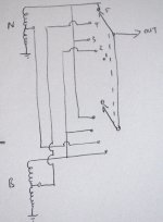
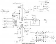
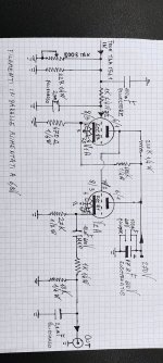
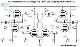
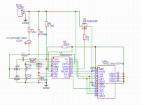
Here is the schematic as currently operating:

An externally hosted image should be here but it was not working when we last tested it.


The main idea is to provide a fixed reference voltage for the driver
anode and power tube grid (fixed bias) while coupling the driver
anode into a mu-follower to isolate the driver from the sudden onset
of grid currrent.

Q2 and R3 provide a DC reference with high AC impedance. I made R9
adjustable to allow dialing in the bias voltage. Good thing, too...

Q1 provides a high impedance AC load with fixed voltage to the
driver anode, and provides a low impedance mu-follower output
to drive the power grid.

Q1 is supplied by a separate stacked power supply (ultra simple)
which is returned to the cathode of the power tube such that the
grid current loop does not include the driver power supply.

As shown below, it works quite well, with the 5842 driving up to
300V P-P to the 4-65A grid (to +70V in this trace) while supplying 50mA
of grid current:

An externally hosted image should be here but it was not working when we last tested it.


The 4-65A triode load line I am working with needs about 260V P-P
drive, going about +40 maximum, so I have some headroom in this
drive circuit.

I'm also thinking about smaller screen grid resistors.

I am getting about 16W output, which the 10 Watt Transcendar
OPT seems to handle remarkably well. I was worried looking at the
waveforms on the scope but the low end is quite nice sounding.
I haven't done an A-B comparison with my 16W push-pull amp but
this one seems to play quite loud before the distortion gets
objectionable.

The distortion spectra is all 2f up to ~1 watt, then some 3f + 4f,
etc in a waterfall pattern increasing up to about 10 watts, when
the higher order harmonics start filling in. I just made some brief
measurements and have been listening to it on and off over the
weekend. It has a very neutral sound, flat frequency response, and
sounds great with some drum parts I usually find challenging for
tube amps.

Cheers,

Michael

CD laser KSS-210A - Nad 5440 CD player

Hi all,

Just bought a replacement laser unit KSS-210A. I removed the anti static solder blob and fitted it but it does not work (spindle motor does not spin). I noticed that the new laser unit has a resistor (small black one) on the circuit board above where the anti static link was... my old laser unit is missing that and looks like it was snipped off. Any ideas?

Thanks,

D.

OB-BOW concept for ESL bass ?

Open Baffle - Bass On Wall (OB-BOW) for ESL bass and lower-mids reinforcement

Here's an idea to kick around for dealing with the perennial ESL bass augmentation dilemma. I havent seen this done so it needs input from the brains trust about feasibility please. If you are anti-OB bass please kindly ignore. This is about OB.

ESL's can be extraordinary in the midrange but struggle with bass. Some ESL can even struggle with lower mids giving a thin sound lacking body and warmth. A friend with Acoustat 2+2 wants more bass but not from a box subwoofer. He listens to rock, jazz and classical and only wants bass to 40Hz. He wants bass that can integrate with the ESL's and also fill in the lower mids.

With a large room the ESLs can be positioned in from the side walls. This gives a great site for an open baffle for woofers to be sited against the wall like in the red below:

1647101904066.png


Design ethos:
  • Plain baffles avoid the resonance issues of H-frames etc. and so allow a higher frequency reach to fill in the lower mids for body and warmth.
  • The ESL and OB both being large dipoles, should blend well with similar impulses.
  • The open baffle when placed against the wall will have improved efficiency.
  • The OB and ESL are in the same plane with a good gap. This places the ESL membrane in the OB null and is decoupled from being driven by the bass output.

Driver:
For OB bass drivers there is a 12" GRS 12SW-4 at just $32 each which allows six per side x2, for only $380.

Hornresp:
The lowest bass instrument he listens to is the bass guitar at 41Hz so with a 40Hz cut off, hornresp indicates one side can do 124dB:

1647102744203.png


Impulse looks good too:

1647105849197.png


This all seems to good to be true. I assume Ive made multiple mistakes in Hornresp so I exported the file and attached it below. Its just a txt file of 2kb file so its tiny and safe. Ive attached it just in case anyone wants to download and save it in the "import" Hornresp folder to check it out.

Attachments

New Issue Crosslinking

There still exists a problem on this forum where I reply to on thread, but it's posted in the previous thread I was reading.

Today I almost posted "My setup on a monobloc with 3300µF/450V (Surplus for 6$CAD so why not?)" as a reply to an audio cable thread, but as you could imagine, I was replying to the 4100µF thread... I lost my S*** once on this and was punished on the old software. I have thought It'd been fixed by now.

JL 500/5 one PS failure

IRFZ44R blown in one of this amps' two power supplies.

I pulled out ALL IRFZ44R in both supplies. Cleaned up the board and replaced gate resistors. I'm finding terrible looking drive signal on the gate pads of the side which blew. Pulled driver transistors. Signal coming from the IP3525 (SG3525) pins 11 and 14 looks like a bunch of mess. Also the IP3525 does not have clear osc pin 4.

1. 0.031
2. 5.13
3. 0.296
4. 0.517
5. 2.261
6. 3.897
7. 2.607
8. 4.5
9. 5.21
10. 0.031
11. 5.04
12. 0.031
13. 13.05
14. 3.820
15. 13.05
16. 5.13

I'll post some images of both IP3525 OSCs next

For sale: 6ft of TFT20 Teflon Tubing Thin Wall 20AWG for component leads, $6 USA

For sale: 6ft of TFT20 Teflon Tubing Thin Wall 20AWG for component leads, $6 includes postage to USA only.

This AWG20 thin walled Teflon tubing is perfect for insulating component leads, rated 200V. For your $6 I will mail you six feet of it in a small envelope marked "non-machineable" (so NO tracking!).

If you want longer lengths just ask and we will figure out a deal.

It is not a substitute for heat shrink tubing.

Thanks,
Keith

tubing_tft20_7915.jpg


tubing_tft20_7916.jpg


tubing_tft20_7983.jpg

Audio-technica ATU4030LC phono cartridge $30 + ship USA

For sale: one used Audio-Techinica ATU4030LC phono cartridge, $30 + shipping USA only.

This is a thrift store find, so I don't know anything about it and can not test it in any way.

You will_need to replace the stylus! And as you can see in the photos the stylus guard is not included.

Included with the cartridge is the original box with tools and installation guide. You can, of course, read reviews for this cartridge online.

Shipping in USA will likely be about $5 First Class mail.

Thanks,
Keith

audio-technica_7993.jpg
audio-technica_7988.jpg
audio-technica_7989.jpg
audio-technica_7990.jpg
audio-technica_7991.jpg
audio-technica_7992.jpg

AD5791 recommanded receiver

Hello,

I work on designing a DAC prototype using the AD5791 (SPDIF only for the time being)

Although I am familiar with the old DACs such as the AD1865 (see the DAC End from Andrea Ciuffoli for example) and have already built a few of them, I have difficulties to understand how to connect a receiver to the AD5791.

Analog Devices gives an example of Typical Operating Circuit in the datasheet (see attached) but no example of a receiver connections;
I have started a design with the CS8414 but I had to stop because I don't understand how to feed the DAC major inputs: SYNC (inv), SCLK, SDIN, SDD, LDAC (inv), CLR (inv), RESET (inv) ??

Do you have such an example of Receiver <->AD5791 connections ?

Thank you

Attachments

  • AD5791 Typical operating circuit.JPG
    AD5791 Typical operating circuit.JPG
    99 KB · Views: 262

TDA1541 and others current out DAC tube out stage.

Hello! I would like to know your opinions on this output stage that I am attaching in the photo.
The only difference is that my current psu can only supply 230Vdc and not 270Vdc.
I must say that the sound result is amazing!
Any advice from you would be precious to me!
Granzie in advance.
Antonio.

Attachments

  • IMG_20220319_215722.jpg
    IMG_20220319_215722.jpg
    409.3 KB · Views: 614

How to build the perfect ported cabinet. ...

After having fooled around in this hobby for more than 25 years, I would like to share the "rules" I follow when I build two-way ported loudspeaker cabinets.

1. The first I do is to choose a midwoofer with Qts around 0,30 for standmounts and around 0,40 for floorstanders, that seems to be the sweet-spot. And for midwoofers I prefer motors with copper above and below the air gap (Seas Excel, Scanspeak Revelator), not inside the gap (Satori, Audio Technology, Wavecor). Midwoofers with copper inside the gap may sound superior in the midrange and in the lower treble, but I my opinion they lack punch and power in the bass and lower midrange. And I like the midwoofer's Mms to be no lighter/heavier than 7-8 cm2/gram, that is another sweet-spot that goes well with the Qts.

2. I then use some software to estimate the cabinet volume and port tuning, aiming for a system-Q around 0,70. The cabinet can be larger, but not smaller than 0,70. If space permits, I like the port area to be 30-35% of the midwoofers Sd. And I like to place the round(!) port on the front. The port opening inside the cabinet should be placed on a small baffel. The inside opening schould be placed in a golden ratio distance from the top and bottom of the cabinet.

3. And then the time consuming work begins. I know you can add stuffing inside the cabinet to balance the port response and to damp standing waves, this is a quick and easy fix but in my experience, the less damping inside the cabinet, the better. Lining the walls with ¼" wool felt is ok but even the slightest amount of volume stuffing almost always lead to a less lively and less open and less powerful loudspeaker. So I never stuff. Instead I build the cabinet with angled reflectors at the top and bottom, with lots of non-symmetrical shelf-braces in between, to break up the standing waves without choking the driver/port.

4. Most of the backwave energy will escape through the port and cone, that is how a ported enclosure works, and I don't want that sound to be coloured by vibrating panels making the speaker sound boxy and woody. For the walls I use two ½" thick birch plys in a CLD construction with a flexible one-component marine adhesive sealant, with three ply layers for the baffle. I prefer the stiffness and "sound" of birch ply to MDF. This birch ply CLD, in addition to all the bracings in #3, adds enough stiffness and damping to make the cabinet dead enough. And I aim for a total mass of the cabinet 1200-1500 times the midwoofer's Mms, I don't want the midwoofer to be able to move the cabinet.

5. I always make the cabinet as deep as possible. In my experience, a midwoofer needs a minimum of 35cm distance to the cabinet's back wall. I don't know why but midwoofers always sound better in deep cabinets.

6. I always remember to test the finished loudspeaker using an amplifier with a high enough damping factor. It is easy to mistake an underdamped midwoofer/amplifier combo for a badly tuned ported loudspeaker. Even the world's best SET amplifier can make the world's best loudspeaker sounding like a boombox, if the two don't match. For SeasExcel/ScanspeakRevelator Qts 0,30-0,40 midwoofers with 7-8 cm2/gram Mms I prefer BJT amplifiers, by the way, these type of midwoofers need – and deserve – power!

So, that is my "handbook". It would be interesting to hear what others may think.

Internal wirering for a waffle maker?

My loved Waffle Maker stopped working. Root-cause was a few wire that broke.

So, what kind of wire would you use internally in a waffle maker?
  • Its hot ( dont know how hot, but hot)
  • There is oil and fat leaking into every part, so wire must be resistant to that.
I have some stanard PVC-wirering, some silicone and some unknown fibre-protected wire.

Any ideas?

Kind regards TroelsM

Sad...

I can't stress enough how much i looked for these transistors even as second hand as they are and how sad the new datasheet makes me feel...I wonder ...what's better than these today?

Attachments

  • 20220418_080410.jpg
    20220418_080410.jpg
    444.5 KB · Views: 472
  • Screenshot_20220418-075835_Word.jpg
    Screenshot_20220418-075835_Word.jpg
    104.2 KB · Views: 473

NAD 3400 & 7600 Parts and remote wanted

Hi

Looking for missing knobs for my 3400 amp. The small square ones, for the frequency selector between bass and treble pots.
Also misses those round black and green plastic knobs.

Original remote if any one will sell.

Rack mounts for monitor series.

Front plate for the 3400 & 7600.
Both mine has scratches and bent sides.

I'm in Norway

Attachments

  • IMG_20220311_091901.jpg
    IMG_20220311_091901.jpg
    172.3 KB · Views: 149
  • IMG_20220311_091916.jpg
    IMG_20220311_091916.jpg
    187.1 KB · Views: 139
  • IMG_20220228_130239.jpg
    IMG_20220228_130239.jpg
    275.3 KB · Views: 139
  • IMG_20220223_223819.jpg
    IMG_20220223_223819.jpg
    257.2 KB · Views: 202

Modulus 86 CHEAP build

After weeks of research Ive decided to build a stereo amp based off of the modulus 86, but it had to be cheap. Really cheap. I decided to disassemble and recycle an older amp to help cut down on the number of purchased parts. I picked up a sonamp 260 on ebay that was in bad shape. It had been dropped and had a lot of damage to the boards. Perfect candidate. Unfortunately, the transformer put out far more voltage than i could use, so I decided to go ahead and try a meanwell I picked up for $15

Attachments

  • IMG_20220321_190801095.jpg
    IMG_20220321_190801095.jpg
    248.3 KB · Views: 340
  • IMG_20220322_094048190.jpg
    IMG_20220322_094048190.jpg
    370.4 KB · Views: 357

When not to use low leakage KL?

Hey all. I'm looking for a good choice to replace all the Nichicon FG capacitors on my amplifier output boards (while the sound is good, it's just too warm). This is a Class AB amp circuit. While looking at different choices and researching caps, I found this Nichicon KL low leakage cap. Would anyone feel that there should not be a place to use this specific cap?

I did come across another post about Nichicon VX, KZ and FG caps all being very low leakage, which supposedly was the reason for the excellent bass response.

The KL caps are physically sized very close to the FG caps (in some cases the same size). They also have much higher ripple current specification then other caps (even KW which is already has a high ripple current spec).

I have been trying to read as much as I can on "low leakage" and the consensus is that most modern caps are already considered low leakage. However, it would seem this KL takes things further. Best I can tell, low leakage is absolutely recommended on precision measurement circuits or high DC decoupling caps. But are there any other reasons NOT to use a low leakage cap such as KL?

I do know that it is not recommended to use low impedance caps in an analog section, but these are not listed as "low impedance" on the Nichicon datasheet.

Alternatives that I'm looking at are 105 degree VZ (worst ripple current specs), KZ (if I can fit them) and KW.

Listening area inside of a 20hz horn?

I have been dreaming of building a theater/listening room where the room itself is the horn. For the sake of simplicity of construction it would be a slowly expanding conical horn with rectangular cross section, where the walls and ceiling would expand out from the sound source at whatever flare rate is appropriate for loading the drivers down to 20 hz, and terminating wherever a good sized listening area is achieved. The entire rear wall would be a very deep acoustic absorber; contemplating the use of wood chips on the order of 6 or 7 feet in depth, contained behind wire mesh, a layer of foam, and fabric.

Thoughts?

Opinions on Mods to FF85wk

I am using ff85wk in Planet 10's great uFonkenwk. I'm hearing a little bit of harshness and would like to do something. Due to financial constraints and/or
lack of skill to do it myself, I am unable to do the enable treatment. Would I be better off leaving them stock or would I at least see some benefit with one or two light coats of Mod Podge? Please understand this is in no way a put down of Planet 10's time consuming process. Thanks for any suggestions.

FS Big DIY tube lot 450+ tubes $250

I have a big stash (450+) of great DIY suitable tubes. All of these are useful for audio and/or boat anchor applications. No useless crap! Lots of 12v, loctal, top cap, etc. Examples include 1625, 6080, 6159, 2e26, 12j5, 12sn7, 12sl7, 7b4, 14a4, EL39 etc. etc. etc. The spreadsheet has some info. Most tubes Are NOS in box, they do not have any additional labels except maybe the brand. Ones that are labeled NB means no box or reboxed. Some of those I know are actually NOS so I've labeled them as such. There are a few tubes that are known to be used but have tested values on the packaging. I've labeled them "Tested." Other than those, none of them have been tested although they are all supposed to be good tubes according to the sellers over the years. Take that for what it is worth...

I want to sell this as a lot so I've put a good price on it for DIYaudio folks $250. I'm partially disabled and so they will need to be picked up at my home in the DC area. I'll bump the post from time to time...

Attachments

  • Like
Reactions: Gill.T

Mar-Ken 12p with side vents

Hello DIYers,
Hope you can help. I’ll make it short. I have the 10p in a Pensil and a 12p in a 19L Base Reflex which does not impress me much. I love the Pensils, bass is enough for what I listen to. I would like to find a better (imaging, detail, finesse, soundstage) enclosure for both. No SuperPensil 12p or FHXL since space will not allow it but would like a floorstand(10p or 12p) and a standmount(10p or 12p). I was thinking of the Mar-ken with side vents (Dave's design) standmounts or MA 12p in a Juliet or CGR Mar-Ken 12p. and the Mar-ken 10p floorstand.
What would the Mar-ken with side vents (Dave's design) standmounts bring over the Pensil? Would the Mar-ken with side vents bring enough bass to the table? What do you think would be the better box for the 12p?
BTW The speakers will be fed with a Finale 6watt EL84 tube amp.

Thanks

Remote IR stopped working? Wadia 860

Looking to debug a problem with a Wadia 860

The Remote Control no longer functions? - both the original remote and a universal remote.

Before opening the lid I thought I would ask some questions....

Background -
Original owner - been working flawlessly for 15 years, has not been moved or fallen.

Does the IR receiver occasionally fail in these things?
Is there someway to test? - (have a decent Fluke Multimeter)

I've done the simple things, check batteries, clean receiver

There is not much support from Wadia these days - and the front buttons on the unit only control track advance, volume and opening the tray (which allows it to still function) but you cannot control the source inputs, programming, phase, repeat and some other functions.

Thanks for any guidance

Various 1stW Clone related parts for sale

SOLD


In the process of building (and learning about) some F6 monoblocks, generated a passel of parts I don't need anymore.
Asking $150 (incl. shipping). Due to weight, US only sale. If in the Denver area, $100 and I'll drop it off somewhere.

Pictures attached.
List includes:
2x Hammond 1182G18 (18VAC secondaries, 225VA)
2x GBPC12005 12A bridge rectifiers (12A)
4x GBPC2502 25A bridge rectifiers (25A)
3x diyAudio PSU diode boards; blank, 1 set of boards is split
1x diyAudio PSU filter board; blank, split
2x diyAudio PSU filter boards, built w/ 35VDC caps, 60kuF per rail
6x SL15 thermistors
1x Schurter 4304.6090 IEC power module
2x 4Ux300mm heatsinks (non-UMS, untapped)
4x 2mm aluminum Mini-Dissipante 23/300 covers
2x 23-250/300 base for Mini-Dissipante
4x modushop puck feet quad
2x Dissipante hardware kits
1pr. 0.5m Kimber PBJ RCA interconnects
20x 0.25" PCB quick connect tabs
var. power busses
var. zener diodes
var. quick connects

will not separate as I want to get rid of this stuff but not via landfill.

Attachments

  • IMG_0037.JPG
    IMG_0037.JPG
    1 MB · Views: 119
  • IMG_0038.JPG
    IMG_0038.JPG
    784.7 KB · Views: 107
  • IMG_0039.JPG
    IMG_0039.JPG
    866.9 KB · Views: 108

MJR7-Mk5 by Renardson

Hi

I try to build Mike Renardson´s MJR7-mk5 amplifier. I made my own board design but someting is wrong. I have now tied to find the problem, butt no sucscess.
The 2A fuse bloves when i power on, but not a 2.5A fuse. With a 2.5A fuse the R13 gets extremely hot. If I messure without T6 and T7 connected I get 40V at every point around Vr1. The rail are 67V.
I staring me blind at this so I can´t se the problem. Can someone check my drawings?

Attachments

6AU6 Circuit

Before anyone makes fun (and I see many doing so here sadly) I am a tube novice, grew up on germanium transistors and just never felt the need to understand tube circuits.

I have a circuit built (using an apparently well known and proven circuit) based on 6AU6 as a pre-amp. Its fed by +/- 30V, Mullard tubes and built on a PCB.

It works, driving it with 50-100mV 1kHz tone it's gain appears to be around 5, which is fine for my need. Now, without connecting any external source to the input (across 1R35 in the circuit below) the output is stable and hum/noise free. However connecting anything to the input (ground or signal side) creates a very high 50Hz hum. Even placing a direct short across the input the hum is present, though the 1kHz tone is killed. I tried shorting to signal ground and chassis ground and then bridging chassis and signal grounds, same.

I "feel" the input impedance is somehow compromised even though there is a 4k7 resistor, and that the actual impedance might be very high.

I cannot figure the circuit so if someone can assist in indicating the likely input impedance and what I need to change to increase/decrease the gain. Any pointers as to why this hum occurs will also be appreciated.
1650727249618.png

1980s Peavey Ultra HiFi Constant Directivity Sp3

It is so very interesting that the original Peavey Sp3 Cabs with the original Eminence woofer
(Very similar to the Klipsch K33) and the 22a (aluminum version) on an 800 hz ev cloned Keele style horn just kicks *** with the original xover and some CD horn eq.
Sure it cuts off around 80 due to the very short bass horn
But boy does that horn ever seamlessly integrate with that Keelish 800hz horn off the 22a driver.
I think Earl Geddes would appreciate how seamless this is.
I know a lot of us have played with the Sp1 (a clone of the LaScala) but I have rarely heard of anyone playing with the old sp3 which is a clone of the JBL perkins type midbass unit.
True hifi here guys smooth as a babys ***. I will try to get some plots up soon. Heads up guys this is a whole lot of great cd speaker for very little money. Impressive. Add Subs and enjoy. Remarkable. Also worth pointing out that Peavey CH-1 500 hz horns and CH-2 800hz horns are much much underated. Really these are Keele style EV horns. Agreat era for horns imo. I am pleased

Dayton Audio OmniMic

My Dayton Omnimic isn't giving the same results as my other calibrated microphone running JustMLS (LspCAD) and I'm pretty sure it's the Omnimic that's not working properly.

I've tried everything the guys have suggested over at the partsexpress forum but it always displays a high frequency droop, but I get the impression that partsexpress think it's user error.

Before I send it back to the USA, I just wondered if anyone here in the UK has one that they could compare to mine? I'll happily send it to you and pay return postage. It just seems a waste sat in the cupboard doing nothing.

AC on +V output of dual rail linear regulator supply?

Considering the dual rail linear power supply circuit diagram at the bottom of this page (https://sound-au.com/project05.htm), what might cause the +V rail to have ~30V AC as well as +15V DC, while the -V rail has 0V AC and -15V DC?

i.e. what could cause the +V rail to have an AC component?

I suspect bad rectifier diodes. But those have been replaced (not sure if replacements were good), and the issue persists. Anything else to check or replace, assuming a cheap DMM and no oscilloscope?

dummy load - wattmeter

hi friends,

glad to come back after a long interruption. I start with a smooth project. I have 4x 8ohm non inductive resistances. It gives me idea of an audio dummy load with wattmeter, something like sencore PA81.

For dummy load part, I think of
  • 4 to 8 ohm switch with extra contacts for correct display value
  • thermal switch for fan
  • DC protection warning
  • BNC output

for wattmeter I think of something around AD637.

advices are welcome and if something exist, I don't want to reinvent wheel

Attachments

  • DSCF0929.JPG
    DSCF0929.JPG
    302.5 KB · Views: 192

Any advice on cutting sorbothane sheets?

I bought an 1/8" thick sheet, with the hopes of cutting a few gaskets for vibration control.

This stuff is nearly impossible to cut cleanly, or even cut at all. It takes several passes to even break through to the other side, and then I have to flip it and cut some more. It pulls, stretches, and eventually slices, but it's ugly. At least it's tacky enough to help hold a straight edge guide.

Any tips? I even tried a razor blade (a real one, made for double edge wet shaving).

Distortion Analyzer - Circuit to build

Hi!

I found this Distortion Analyzer circuit diy project.
You will need 4 op-amps (2 dual).
Wouldnt it be nice to be able to checkout
if your amplifier show more or less distortion, after you have modified it.

1.0 Volt AC at output means 1.0% distortion.
Note, you will need a good multimeter, which can measure AC-voltage at frequencies above 400 Hz.

Article:
http://www.ethanwiner.com/distort.html


Build a Tape Linearizer and a Distortion Analyzer
by Ethan Winer
This article first appeared in the December 1981 issue of Recording-engineer/producer magazine.


SETUP AND USE

Once you've completed building the unit, plug it in, turn it on, and pray it doesn't blow up! If it passes the smoke test,

take a voltmeter and check each op-amp's output pin - these are conveniently located in the corners of the IC. The DC

voltage should be within a few millivolts of ground; if it is not check your wiring and/or try another IC. Now you are

ready to begin measuring distortion. The first thing to measure should be your sine wave oscillator, so connect it to the

analyzer's input.

Start with the output frequency set to 1 KHz., the function selector to Set, the null pot in the middle, and the analyzer's

gain control at minimum. Now adjust the oscillator to some reasonable output level, and increase the analyzer's gain

control until its output reads 10 volts on an AC meter. (Note that many digital multi-meters do not have a frequency

response that extends beyond a few KHz., so an analog meter is a better choice. Also, since the test procedure involves

nulling, a mechanical meter is much easier to interpret.)

With the full-scale set at 10 volts, switch the function selector to THD, and alternately adjust the null pot and the

oscillator's frequency to obtain the minimum reading possible. Now select the Divide by 10 switch setting and continue

tweaking until you are satisfied that you have completely canceled the 1 KHz. fundamental tone. You are now reading

distortion directly in percent - that is, 10 volts equals 10%, 0.1 volt equals 0.1%, and so on. You will probably find that

due to capacitor tolerances, the 1 KHz. setting is not precisely 1,000 Hz. Again, it doesn't really matter, but you should

make note of the actual frequency to save time in the future. Try the same thing at 100 Hz. and at 10 KHz. (or whatever you

choose), and you'll be an old pro in no time at all.

Circuit:
dist-4.jpg

Budget audiophile speaker cables

I have read so much info on audio cables, my mind is spinning. I've read everything from CAT5 to Home Depot power cable.

Here's my story - I'm running all digital, with active crossover. About 75w per channel max power. I want a fun project with the kid. I'm not looking to buy shares of some Russian mine to come up with exotic materials for 20' of speaker cable.

I have a huge spool of in-wall speaker wire - which is really nicely packaged for making cables. However, I want to do build a set, and listen comparatively.

If this is in the wrong category, apologies in advance. Please feel free to move this thread.

Thank you.

Alpine MRP-M650 Schottky Barrier Rectifier? “SK 2B”

I’m not to familiar with these types of diodes, just wanted a confirmation that it is in fact bad as I am interrupting from the DMM testing, and that I do have the right data sheet for this component so I can buy new ones.

D403/SK 2B: DMM Diode mode shows 0.012-0.13v both ways, from what I’ve read I am supossed to get between 0.2-0.4v one way, all 4 are reading similar.

Also wanted to confirm that I do have the right data sheet, I think I do but I don’t want to just assume.

Half the high&low outputs blew due to abuse and very bad environment conditions. The 4 to the left if looking at board right side up, 4 to right if looking at pic as is, upside down.

Thankyou 🖖🏼

Attachments

  • AB857858-073E-4128-B96F-A7BF227E444F.jpeg
    AB857858-073E-4128-B96F-A7BF227E444F.jpeg
    541.9 KB · Views: 99
  • 7075EEB4-A363-40F7-B44D-29D14CE59EA8.jpeg
    7075EEB4-A363-40F7-B44D-29D14CE59EA8.jpeg
    578.8 KB · Views: 103
  • A1891F6D-21EF-4597-93EB-FE4382F4F1C4.jpeg
    A1891F6D-21EF-4597-93EB-FE4382F4F1C4.jpeg
    637.8 KB · Views: 93
  • CD7D7F3F-486B-4DD3-8523-D21ACFB9A78E.jpeg
    CD7D7F3F-486B-4DD3-8523-D21ACFB9A78E.jpeg
    190.1 KB · Views: 90

Eminence KL3012HO 2-way cabinet design

I have a pair of Eminence Kappalite 3012HO 12" drivers that I wanted to build some compact 2-way monitors (doubling as small PA tops) with. For the CD and WG combo I chose 16 ohm B&C DE250s and Eminence WG10s.

Crossover will be passive, but may use a dual channel plate amp with built in dsp down the road. For now I want to keep it simple and basic.

The question is what xover point and cabinet design would you prefer to use based on LF driver performance data? I would definitely choose tighter / cleaner low end response over output capability.

Anyone have experience with this Eminence driver? It looks and sounds nice from the little bit of listening tests I've done so far in 1.5 cu ft sealed test cabs. I was leaning towards maybe some slight LF driver WG loading to increase lower mid projection outdoors and to align acoustic planes of both drivers for easier xover.

Attachments

  • 20220422_164554.jpg
    20220422_164554.jpg
    213.4 KB · Views: 134
  • 20220422_171050.jpg
    20220422_171050.jpg
    72.4 KB · Views: 132

Altec 1712a Switch ON/OFF Switch replacing

Hey all, this is my first time posting here so excuse my stupidity.

I purchased a couple of Altec 1712a's and I'd like to change the ON/OFF Push Switches which are soldered to the board..

1650592614693.jpeg


1. The Current Switch is a... Schadow TVR NE15 - DPDT. 4A/ 250VAC
1650592118357.png


2. I'd like to replace it with a Toggle Switch that would have to have right angle pins so that i can solder it to the board.
1650592342244.png


I'm struggling to find a toggle switch with right angles pins that's 4A/250VAC

Can anyone help? Thank You

My Invention

Self explanatory I guess -- all but the electromagnets (silver disks)
I picked up a pair of the magnets to experiment with, shocking how powerful they are, and only need a tiny 9 volt wall adapter for power.
The wall adapter is in a powerstrip with a shopvac, push the hold-down where you need it and turn on the power, It comes to life!
Oh boy they are powerful, they miss the iron deck by a little bit here, but they still cannot be moved.

I don't have a link for electromagnets, but there are out there, the cost was very reasonable.


Mags.jpg
  • Like
Reactions: GM and Johno

Computer games

Perhaps some would be interested in a thread for PC games?

I do not have much time for these things anymore, but I just recently purchased Forza Horizon 4 (Ultimate edition).
And I have missed playing racing games, so much fun!
Now I've been having some issues with the entire game slowing down for some weird reason, even though I have more than enough hw to get higher than 60fps with most settings on Ultra. Just found out it may be related to some issues with the ridiculous "Windows Game Mode", hoping I will get it working this evening.

Forza 7 was a big letdown for me, with the homologation limits that I really did not understand, the auto homologation thing that was just horrible, and the game itself full of those annoying loot boxes and whatnot. For some reason buying a specific part would break some kind of rule or limit and it was sometimes a bit difficult to figure out which part was the culprit. If it was fixed in some patch I would'nt know, dropped it like a stone.

Been a big fan of the Civilization series for a long time, had probably over 4500 hours on Civ 4 with BTS expansion. Civ 5 and 6 felt very "unfinished" when they came out, so have sort of lost interest. Hoping that perhaps a future strategy game will be able to catch my attention. Really liked the old Alpha Centauri. And ofcourse things like Masters of Orion 2.

Really looking forward to "Outer Worlds" from Obsidian!
The Outer Worlds
Finally another spiritual sequel to the Fallout series!
Loved Fallout 1 and 2! Fallout 3 and 4 isn't really Fallout, Bethesda has managed to ruin it properly, thankfully they eventually had the sense to ask Obsidian to do Fallout New Vegas, which was a great game.

USB charger

Hello, I am designing a USB phone charger. I want to put this in my PSUs, so I can charge my phones and laptop.

Here is the schematic.

The JD6606 is controlling output through the power FET. According to its manufacturer, it can go upto 20V. However, when I go over 6V DC in input, it stops working.
If I keep it under 6V and put my Samsung Galaxy, it says "fast" charging and consumes 7-8W (output is 5V). I want to reach 12V and 20V to be able to charge my laptop too.

I am thinking to keep Vdd 6V, despite the input on the FET. But I don't know if I have to touch feedback or anything else. Any ideas?

Attachments

  • USB_charger.png
    USB_charger.png
    40.5 KB · Views: 136

PS4 SOURSE

I already know some of you will be laughing.. Im using ps4 for source and spotify. would a streamer make a noticeable difference? if so would I get better bass? better sound stage? louder? have any of you switched from ps4 or xbox to a streamer? Budget £500-£700. I only listen in multi channel 2fronts 2front highs. may one day get rear heights

Making audiophile power cord and have question about using crimping cable ends

Hello!
I have read often diyAudio forum and find lot of useful information, thanks for forum members. Now I have some question for members who have made audiophile AC power cords. Do you use scrimp cable ends sleeves with multicore cables? I know that without is better but with thin multi core wire it is necessary. If the cable is silver plated and plugs are also silver plated is it better to use silver plated copper cable ends sleeves also? Theses silver plated cable ends are available in some audiophile online stores. There will be always some air between cable end sleeve and wire cores left after scrimping, will the corrosion and with air formed sulphide will be problem in some years. Like to make as best power cable as possible. Thanks.

Seas CA18RLY or CA18RNX for floorstander

I want to make BassReflex floorstander with 6" Seas Prestige. My first priority is extended bass response, no matter what size box will be. I'm in mix between Seas CA18RLY and CA18RNX.

Using Hoge's formula I got:
CA18RLY - f3 = 31Hz, Vb = 55L
CA18RNX - f3 = 47Hz, Vb = 17L

Obviously CA18RLY seems like better choice, but Troels Gravensen mention several times that RNX is better for bass, and now i'm confused 🙂

"The CA18RNX is a long-throw, large voice coil variant of the Prestige paper cone drivers handling bass better than the CA18RLY, which holds the classic 1" voice coil."

what do you guys think?

Resistor matching error starting with six 1% resistors

I got interested in obtaining better-than-1% matching of metal film resistors, especially "uncommon" values among the E96 series of standard resistors, that are not offered / are not stocked in the (much more expensive) 0.1% tolerance grade.

I decided I was willing to buy six resistors and pick the best matching pair among them, then discard the other four. So I put together a little Monte Carlo simulation to see just how good or just how bad the results might be. Assumptions built into the simulation
  • Resistors are "100 ohm, 1% metal film" devices. Smallest possible resistance is 99.00 ohms, largest possible resistance is 101.00 ohms
  • Resistances are uniformly distributed; all values between 99 and 101 ohms are equally likely
  • Mismatch between two resistors is defined to be [(Rbigger - Rsmaller) / Rsmaller]
I fired up the computer and performed one hundred thousand trials. Each trial consists of: (a) Generate six random resistor values, uniformly distributed between 99 and 101 ohms; (b) for each possible resistor pair, calculate the mismatch; (c) report the best [lowest!] mismatch of all possible pairs. Results, in ascii .csv format so anyone can slurp the data into a spreadsheet, were:

Code:
mismatch,count
0.00000,13990
0.00010,12335
0.00020,10917
0.00030,9358
0.00040,8251
0.00050,7289
0.00060,6197
0.00070,5345
0.00080,4558
0.00090,3854
0.00100,3301
0.00110,2781
0.00120,2263
0.00130,1926
0.00140,1558
0.00150,1359
0.00160,1047
0.00170,816
0.00180,659
0.00190,536
0.00200,420
0.00210,346
0.00220,253
0.00230,180
0.00240,136
0.00250,110
0.00260,78
0.00270,64
0.00280,36
0.00290,15
0.00300,10
0.00310,8
0.00320,1
0.00330,1
0.00340,1
0.00350,0
0.00360,1
0.00370,0
0.00380,0
0.00390,0
0.00400,0
I made two histogram plots, one with very few bins and another with very many bins. They are shown here.

I have to say, I'm delighted by these results. About once per ten thousand trials, the best match is "terrible", namely 0.31 to 0.40%. On the other hand, there's a 55 percent chance that the best match is "fantastic", namely 0.05% or better. Woo hoo.

attachment.php


attachment.php


_

Attachments

  • histog1.png
    histog1.png
    12.1 KB · Views: 1,143
  • histog2.png
    histog2.png
    14.3 KB · Views: 857

Iron Core coils on a planar magnetic

WEll i posted a measurement Air coil vs Iron core on a facebook group. i measured the actually output from my speaker to see what would happen (dont mention overal distortion its about the difference.)

And i get allot of comments about what i try to do cant be done, you mic is not accurate enough to measure this kind of distortion and i measure wrong, i have to realign the filter etc etc..

in my honest opinion the way i measured it might not give the greatest detail but will show witch coil i would use and witch i wont in a planar magnetic...

Speaker used Planar magnetic bass, amplifier hypex NC400 class D , mic isemcon emx-7150 perfectly capable of measuring what i can even hear.

FR of the 3mH Iron Core and the 3mH air coil.
FR.jpg

Distortion of the AIR coil
dist AIR.jpg

Distortion of the IRON core
dist IRON.jpg

Impedance measurement of both coils since i was told the filter needed to be realigned and the Q changes because of the significant difference in resistance 🙂 0.14ohm..
Green no coil
Yellow Air coil
Purple Iron Core
impedance.jpg
No what baffles me is the enormous added distortion with the iron core, you can even hear distortion riding on the fundamental. not pleasant.

any idea why this is so dramatic >?can it be something with combining it with a resistive load like a planar ? or is the class D amp going mad ? (would be shamefull)
or is it just Hysteresis Distortion, and these coils would suck in any case.
Projects by fanatics, for fanatics
Get answers and advice for everyone wanting to learn the art of audio.
Join the Community
507,672
Members
7,883,517
Messages

Filter

Forum Statistics

Threads
405,993
Messages
7,883,517
Members
507,672
Latest member
rooomn