Ampohm Pio Xti Nos caps

I have for sale paper in oil tin foil 6 pieces of 0.1uf and 4 pieces of 0.47uf this truly verry good sounding caps. This are new old stock. Never used and new. They are no longer in produktion. Verry natural sounding caps. Price for 0.1uf is 20 eu for a piece and 30 eu for one piece of 0.47uf plus shipping inside EU. I accept paypal.

Attachments

  • IMG_20220503_181939.jpg
    IMG_20220503_181939.jpg
    456.7 KB · Views: 97
  • IMG_20220503_181934.jpg
    IMG_20220503_181934.jpg
    399.8 KB · Views: 118

FS: Eminence Alpha 15A's

Hi all. Being sold by the pair, the famous (ha) open baffle woofer.

Driver info page here.
  • $150 per pair, plus shipping (from NY).
  • Buy three pair for $400 (six woofers @ $66 ea.).
New in box. This is leftover from a larger order, which I didn't end up using.

I'll be posting several threads here in the upcoming week, selling such leftovers.

I've made many sales here the past couple years. You can see my work here: www.aforara.com

Thank you for lookin' and have a lovely day.

DAC misbehavior question

Since many of you on here build your own DACs, I thought you might be able to give me a clue to what's wrong with mine. It's an older Musical Fidelity A3.24, which was one model down from their flagship when it was made. For several years, it sometimes makes a loud 'pop' when I insert a new CD into the transport. It does this with different transports, but it's currently hooked to a Pioneer Elite DVD player.

When it does this, the "Locked" LED on the front panel blinks. But it doesn't do it every time a new CD goes in. I haven't been able to discern any pattern to it. I've just gotten into the habit of muting my preamp every time I change CDs.

Are DACs supposed to mute any un-musical signals related to getting a digital signal lock?

Skar RP2000.1 tl494 power supply issues

Hi all, I have a skar RP2000.1 that is kicking my butt.

All output fets and power supply fets have been pulled. All drive transistors that drive the TL494's output to the gates of the power supply fets have been swapped as the originals were toasted.

When I attempt to power up I can see the gate drive being setup for a fraction of a second then it shuts down. Pins on the tl494 that raise red flags are pin 3 and 16. Both start out at 0v at power up and then swing to 3.81v about 2 seconds after REM is given voltage.

Here are all the TL494 pin voltages. (Second voltage if noted is after 2+ seconds of power being on rem+)

Pin 1: 0
Pin 2: 3.81
Pin 3: 0, 3.81
Pin 4: 3.81, 0
Pin 5: 1.05 (weak oscillation)
Pin 6: 2.59
Pin 7: 0
Pin 8: 11
Pin 9: gatedrive for a quick moment, 0
Pin 10: gatedrive for a quick moment, 0
Pin 11: 11
Pin 12: 11
Pin 13: 3.81
Pin 14: 3.81
Pin 15: 1.37
Pin 16: 0, 3.80

There is also a nearby LM393 whose pinout reads:

Pin 1: 0, 3.65
Pin 2: 3.81
Pin 3: 5.67
Pin 4: 0
Pin 5: 1.86
Pin 6: 1.29
Pin 7: 0, 3.81
Pin 8: 11v

Attached is a picture of the area.

Attachments

  • 20220501_100448.jpg
    20220501_100448.jpg
    590.7 KB · Views: 134

which of these?

I'm looking for a subwoofer for a sealed enclosure with maximum volume of 8ft3 that naturally has bias to 30-40hz with less SPL at 60-70hz. I'd like decent max SPL. I've collected every model in the price range I considered in the attached table. I left off the brand names to reduce brand-bias. I'm leaning towards the woofer identified as "K" in the list. which do you think meets my criteria the closest and why?

Attachments

  • table.jpg
    table.jpg
    528.7 KB · Views: 99

REL Britania Subwoofer - New amp options - considering the HYPEX FA501

I recently purchased a REL Britania Subwoofer with an amplifier that needs repair or replacement. The amp turns on and seems to work for a short period and then stops working - when working there is a constant static hum. When the sub stops working the driver sometimes continues to move even after music is turned off. Sometimes the relay (I think) clicks on and off repeatedly. Basically I think there are likely multiple problems. I've ordered a new relay and new resistors to replace the ones that show signs of overheating but those resistors appear to be in speck so I'm not sure that will solve my problem(s). I'm starting to think replacing the amp might be a better solution and I've started looking at plate amplifier options - specifically the Hypex Fusionamp FA501. Looking for opinions on how best to proceed. Assuming I'm unable to fix the Rel amp do you think the Hypex FA501 would be a suitable replacement? How challenging is the calibration and filtering?
Thanks all!
James

Power supply Linear or Switching

hi,

using a class a amp +/-45v@2amp will be more then 180watts per channel, we have 0.94% trafo efficiency and 1.4volts drop on the rectifiers
90/0.94 + 1.4=97.2volts; 90/97.2= 92.6% total efficiency for the power supply.
THEN WHAY TO USE A SHITCHING POWER SUPPLY?
Did I calculate wrong? What are the benefits of switching power supply when using class a amps?
Best regards

Williams

Psychoacoustic relevance of the ear's HF response on transient perception.

In accordance with Fourier analysis, the leading edge gradient of a transient sound reproduced by a loudspeaker is defined by the high frequency response limit of the system; it is reproduced by the HF, not the LF driver. Given that our hearing deteriorates with age, this could be viewed as applying a low-pass filter gradually reducing perceived HF content as we age, and thus, theoretically, the leading edge gradient of a transient as perceived. (Considering a square wave signal, lowering the filter cutoff would eventually leave us with only the fundamental sine wave).
Imagine a listener who is unable to hear above a 5kHz pure tone and we play an unfiltered piece of music to them. Would this subjectively sound identical to the listener compared with the same piece of music having a 5kHz low pass filter applied, with particular regard to the perception of transient sounds? Phrased another way are we able to discern the difference between being unable to hear above a particular frequency compared with the absence of that HF information in the source, again considering only the perception of transients?

First Watt F4 Clone (Peter Daniels GP) 4 assembled Boards.

For sale four F4 Boards / see at Peter Daniels Group Buy. Boards are full functional. I used them as a balanced version over many moons. All four F4 boards full populated including the Power FETs. Boards used before and all working without any problem. Including the sales are one Power supply Board (PSU size 170mm x 170mm) assembled with 8 Capacitors 27000uF/25V and 4 Capacitors 6800uF/35V and one Softstart Board.
Toshiba FETs 2SK170BL / 2SJ74BL for all Boards available but not included. All FETs I bought from Spencer. I have 2 complete F4 balanced Sets available for sale.

If anyone is interested, please drop me email, asking for all 175€ + shipping. Offers are welcome. Payment through PayPal you must pay additional handling fee 4%. Insured Shipping anywhere is a must. I think it will cost around 28€-45€ worldwide.

Attachments

  • 1_F4 Powersupply_Page_17.jpg
    1_F4 Powersupply_Page_17.jpg
    114.5 KB · Views: 586
  • 2_F4 Powersupply_Page_18.jpg
    2_F4 Powersupply_Page_18.jpg
    77.7 KB · Views: 592
  • 3_F4 Powersupply_Page_20.jpg
    3_F4 Powersupply_Page_20.jpg
    98.3 KB · Views: 584
  • 4_F4_PterDaniel_Page_4.jpg
    4_F4_PterDaniel_Page_4.jpg
    74.3 KB · Views: 569
  • 5_F4_PterDaniel_Page_7.jpg
    5_F4_PterDaniel_Page_7.jpg
    100.9 KB · Views: 564
  • F4 Powersupply_Page_01.jpg
    F4 Powersupply_Page_01.jpg
    93 KB · Views: 281
  • F4 Powersupply_Page_05.jpg
    F4 Powersupply_Page_05.jpg
    105 KB · Views: 243
  • F4 Powersupply_Page_22.jpg
    F4 Powersupply_Page_22.jpg
    83.7 KB · Views: 244

Celestion AXi2050

For sale a pair of new, never used, celestion AXi2050 engineering sample working perfectly and in their box. Selling for a friend that switched from horns to full ranges. AXi2050 are 2" drivers capable of covering a large spectrum from the lower octaves ... considering reasonable offers. Shipping from Italy so EU buyers preferred.

WhatsApp Image 2022-01-24 at 21.44.12-6.jpeg
WhatsApp Image 2022-01-24 at 21.44.12-2.jpeg
WhatsApp Image 2022-01-24 at 21.44.12-4.jpeg
WhatsApp Image 2022-01-24 at 21.44.12-5.jpeg
WhatsApp Image 2022-01-24 at 21.44.12.jpeg

Need help identifying an amplifier component

Hi, this is in a Hifonics A3000.1D car amp. These two components come directly off the Line In RCAs. T101 and T102. I think maybe they are inductors or choke? I'm trying to source a suitable replacement. Kind of hard to see but the board is black next to both of them.
I'm trying to fix this for a friend, I can handle the soldering etc just need a part.
Thanks I appreciate any feedback or suggestions on where to look!
PXL_20220429_001832518.jpg

PXL_20220429_001745548.jpg

Repairing an NAD 3140

I'm re-capping my NAD 3140, and there appears to be a discrepancy in the parts list vs what's actually on the board.

Looking at the parts list, C643 is a 3300PF 50V mylar cap, but on the board I think it was a 47uf 100v electrolytic cap. Unfortunately, instead of documenting each cap as I removed it and ordering based on what was on the board, I ordered off the parts list, and didn't realize that I had a mismatch until half way through.

Also, there was a group of caps in the regulator section that were fried looking, with dark, melted off wrappers. Is there any way to upgrade this section to prevent it from burning out?

I have some pictures attached.

Attachments

  • hfe_nad_3140_2.jpg
    hfe_nad_3140_2.jpg
    506.2 KB · Views: 1,050
  • hfe_nad_3140-1.jpg
    hfe_nad_3140-1.jpg
    240.4 KB · Views: 707

Unknown pre-amp...Any thoughts on it?

Well this interesting thing popped up on a local audio sale page. ($488) No info just a couple pix. (I have requested more info). It's likely from Japan and I'm pretty sure the seller will know nothing about it. Home-made? I am curious what you might think about it. I am not an engineer type, but am very curious what's going on here!. UPDATE... He says"" It work . This design same Audio note but AudioNote upgrade power tube 1 more and improve tube pre for 2 right n left"".....He seems to be saying it's based on the Kondo M7, but is better!

Attachments

  • tango.jpeg
    tango.jpeg
    58.6 KB · Views: 126
  • tango2.jpeg
    tango2.jpeg
    34.7 KB · Views: 120
  • tango3.jpeg
    tango3.jpeg
    46.7 KB · Views: 127

For Sale FS: Full Soekris DAC kit with Amanero USB Interface and Audiozen Control PCB and all parts

FS: Full Soekris DAC kit with Amanero USB Interface and Audiozen Control PCB and all parts

For Sale complete Soekris Dac kit, including:
-Original, not modified Soekris DAM1021-02 R-2R DAC PCB (0.02% resistors, no longer available, still sell for 230U$ for 10% resistors...)
-Parts to mods to Soekris Polymer 820uF caps, and smd resistors.
-Amanero USB interface (original), current price 85U$
-AudioZen, rev 1.2 assembled Control PCB (just need to solder the connectors) and Display kit for Soekris and Amanero (includes also all the extra needed parts, Toslink Receiver, connector, cables, otuput connectors, etc....), original price 150U$ + 150U$ of extra parts
-Also included at no cost 'Universal Signal Isolator' Rev1.2, for Amanero
-All docs for assembly and test.

So you have all the needed parts to build the great Soekris DAC, just need to add an enclosure...
As I said this kit is brand new, never modified or assembled
Will be double boxed for safe shipping

Asking price is less than cost of parts and the 2% resistor DAM1021 version is no longer available. My loss, your gain...

Asking price 550U$ + shipping + Paypal 3.5%

Attachments

  • 118.jpg
    118.jpg
    216.5 KB · Views: 392
  • 124.jpg
    124.jpg
    177.1 KB · Views: 307
  • IMG_20220107_105654.jpg
    IMG_20220107_105654.jpg
    126.5 KB · Views: 265
  • IMG_20220107_105731.jpg
    IMG_20220107_105731.jpg
    158.3 KB · Views: 277
  • IMG_20220107_105759.jpg
    IMG_20220107_105759.jpg
    197.7 KB · Views: 306
  • IMG_20220107_105852.jpg
    IMG_20220107_105852.jpg
    170.9 KB · Views: 287
  • IMG_20220107_105927.jpg
    IMG_20220107_105927.jpg
    369.3 KB · Views: 298
  • IMG_20220107_110010.jpg
    IMG_20220107_110010.jpg
    273.4 KB · Views: 299

Need help identifying an amp.

I picked up this amplifier as part of a lot of items at an estate sale. If anyone can identify the circuit and determine what tubes it requires, that would be helpful. There are no markings or brand labels anywhere on the unit. Thanks in advance.

Attachments

  • P_20220427_182402.jpg
    P_20220427_182402.jpg
    313.8 KB · Views: 134
  • P_20220427_182407.jpg
    P_20220427_182407.jpg
    470.3 KB · Views: 139
  • P_20220427_182436.jpg
    P_20220427_182436.jpg
    360 KB · Views: 143
  • P_20220427_182510_vHDR_Auto.jpg
    P_20220427_182510_vHDR_Auto.jpg
    323.3 KB · Views: 146
  • P_20220427_182548_vHDR_Auto.jpg
    P_20220427_182548_vHDR_Auto.jpg
    244.7 KB · Views: 140

Old posts by member

Say I want to see very old posts by a specific member. I can easily see about the last 100. Then I hit a "View older results" button, which does not do what it says.

Try me:
https://www.diyaudio.com/community/search/member?user_id=5094
At the bottom of the first page of links, I get "1 2 3 ... 10".
Skip ahead to 10. At the bottom of that is the "View older results". Which does not get past page 10 (or for me, a month ago).

Should we be looking to a future instead of into the past?

Paul Carmody Sunflower Redux Quality?

Hi folks! This is my first post on diyAudio. I'm a college student, and have been into audio for over 10 years, and only finally am I making plans to start with DIY speakers. I would like at some point to get into making my own designs, but for now, I am thinking of following another designer's plans. I'm looking for some impressions on Carmody's Redux speakers. Are these any good? They're a bit of an older design, and a lot of the impressions I've found online are also pretty old. Do they hold up today? Are there other, more recent designs that sound better for around that price range? Thanks in advance for your input! (By the way, I am very interested in open baffle, but am willing to forget the idea if the quality wouldn't be up to par)

MTH30 Questions : Complete Noob!

Hi All,

I'm not at all new to electronics DIY and I have some experience with very basic woodworking and access to appropriate tools. That said, the last time I tried to build a speaker cabinet it was in the 9th grade with mitered joints and cleats and, well, let's just say that I didn't get very far.

Ok, that out of the way, being all grown up (outside) and motivated, I've decided that the MTH30 seems like it will be a good companion to my alto TS110s and I want to shake this fear of cabinet building as I have some other projects where ultra-budget is essential.

So, if you guys don't mind, I have some really basic noob questions.

1) I see that the MTH30 calls for MDF. I would rather use plywood for weight, is this a good idea? If so, does it require changing the plan in any substantial way? Any experiences with plywood vs mdf would be helpful here. I don't care about the additional cost if it makes the cabinet lighter.

2) Are the cabinets glued and screwed, or just glued, I can't tell from photos online. They appear to be just glued.

3) From the pictures that I've seen, I'm not seeing anyone line the cabinets with the acoustic dampening material that was found in virtually every speaker made when I was a kid. Do you not need/want this in these type of cabinets? Don't laugh, I really don't know the answer.

4) I'm in the U.S. so getting one of the called for drivers is a bit expensive. I've seen that people have used at least two different alternative drivers that are available from parts express. The RCF LF12g301 and the Goldwood GW-12090. The RCF is $199 and the Goldwood is $99. I also have a couple of JBL tops with 2206s in them that I could borrow temporarily to try out and compare. The question is, what differences should I expect between these drivers? I'm really new to this so I don't yet have any intuition on translating driver specs to real world differences. So, if possible, please be specific and discuss in terms of real world performance differences. I'm not adverse to buying the right driver, but I don't want to waste money on differences that I can't use. I care a lot about sound quality, I care a little less about maximum output.

If it helps this (or these if I build two) are only going to be used for DJ applications, both indoors and out, for small gigs. I largely play somewhat downtempo as well as classic house music, if this helps understand my application. Also, you can assume that they will be powered with an appropriate amp for the driver, so that isn't a factor in which one that I choose.

Thanks in advance,
gs

Looking for speaker plans to go in living room, suboptimal placement, rock/electronic music, sometimes loud

Hello!

I'm considering building my own speakers to go in my living room. The living room has a suboptimal shape - it's rectangular, 3 14' walls and a large opening to the hallway/kitchen/rest of the house:
1651461118450.png


The speakers will go near the fireplace (labeled FP), so one in a corner (sucks but that's the layout of the room), and the other one about 8' from it. Listening distance would be ~12' from the front of the speakers. I mostly listen to electronic music and rock/metal. Sometimes I like to go loud (have measured close to 100dB in the listening spot. I don't do this often but I want to be able to do it). Adding a subwoofer (either purchased or DIY) is an option I am certainly okay with. No particular size/aesthetic requirement, I want it to be fun to listen to. My main system right now is a pair of Genelec 8330A and a 7350A sub, which I use on my desk. I absolutely love how that system sounds - the room correction is pure magic. And I like the analytical sound of studio monitors, but not attached to it.

In terms of amplification, I have not made up my mind yet - I will need to purchase an amp (or multiple). I have a MiniDSP 10x10HD available that I can utilize for this project if I wanted to. Budget wise, I am hoping I can get decent results with $2000-3000 - that goes towards wood, speaker elements and maybe a crossover if I go the passive route. Closer to the lower end of the budget is preferred. TBD about amplifier budget - I could always start with cheap amps and upgrade later. Most of my music comes from Spotify and Soundcloud, although I do occasionally listen to 24/96 FLAC recordings when I can get them. I am not yet sure which source I will be using for this living room. Would likely start with a Chromecast audio and some DAC via the toslink connection.

I have some woodworking experience, and have access to a professional, well-equipped wood workshop - so pre-cut kits are unnecessary. I also enjoy learning new things and playing at the shop.

I tried searching around for plans that fit my needs but there is an overwhelming amount of information, sometimes contradictory. I was wondering if anyone could stir me in the right direction. I am also open to purchasing speakers if that is the best use of my budget, but I am thinking that I might be able to get more bang for my buck by building my own, given that I don't put any value on my time as this is a hobby for me.

Thank you!

Lobing? Beaming? Directivity? René Christensen of Acculution explains.

In the audio realm we talk about “beaming”, “directivity”, “lobing” and “breakup” in speakers. But I find that few people understand what it means. So, I asked René Christensen of Acculution to join me and explain. In the video below, René breaks down the math and gives us practical examples, showing how cone geometry and materials can impact radiation and resonance in transducers.

Please leave a “thank you” for Rene and make sure to leave suggestions for future topics you’d be interested in seeing.

(FWIW, my “interview” videos are not monetized)


Login to view embedded media

Rockford Fosgate Punch 800a2 complete 1 channel meltdown

Fun rebuild I wanted to post about.l and for others. I just received this amp in as part of a larger trade/buy. Classic powerhouse from 1999! Punch 800a2, not the fabled 1000a2 but still 🙂 From those I’ve talked to so far this looks to be a common problem, so figured I’d post repair process, and in case I come across any problems while doing so.

Looks like entire channel has blown, all output FETs bad, some even got so hot they lifted off the MESHA plate (another 1st for me🙂 all resistors on that side all wonky, both SMD and Throughhole types, 2 banks of BJTs look toasted, even a nice crater burned into board (but not all the way through, other side of board looks perfect actually) might need to rebuild some traces(another 1st), even the ceramic capacitor near output terminal has a hole blown through it ...needless to say a lot of firsts for me and excited to dig in on this amp.

Already have some parts on the way.

0.1Ω 5w metal oxide resistor x10 (large t-hole)
5k potentiometers and remote spade terminal
Researching BJTs currently, as with everything

I had some questions regarding the Power Supply and Output FETs. IRF640 and IRF9640, should I stick with NOS FETs of the exact type or is it advisable to go with the replacement N types (IRF640N/IRF9640N) ive been told to but I’ve also been told they cause problems on this board. Any personal experience greatly appreciated, this is more of a learning experience, 1st timers, fun project for me so time is not a factor, so I don’t mind sourcing original parts (640 seem to be hard to find atm) but any other advice/direction/better alternative then stock parts would be awesome to hear about.

I’ll post more as I make my way through amp, currently mocking up a sketch of amp, damaged parts list, stock parts and locations, probably going to recap with new better caps as well, but making notes of everything to do it proper.

Attachments

  • 6C5ACC80-1856-4E3C-A3E9-1F424C493B93.png
    6C5ACC80-1856-4E3C-A3E9-1F424C493B93.png
    955.6 KB · Views: 190
  • 4160C2C6-F5CB-45F7-BDAC-35C66C509493.jpeg
    4160C2C6-F5CB-45F7-BDAC-35C66C509493.jpeg
    529.7 KB · Views: 258
  • 32DE6117-77A5-4025-92A3-512EFFCC3BD4.jpeg
    32DE6117-77A5-4025-92A3-512EFFCC3BD4.jpeg
    776.1 KB · Views: 307
  • 4E51D930-F7FB-4F3C-874D-D099F82517CD.jpeg
    4E51D930-F7FB-4F3C-874D-D099F82517CD.jpeg
    600.8 KB · Views: 208
  • FC70D587-2F77-47BE-82E8-E59921EF7DE2.jpeg
    FC70D587-2F77-47BE-82E8-E59921EF7DE2.jpeg
    555.7 KB · Views: 195
  • BD2A9F8F-1DD8-4A58-A724-3A377D4D048F.jpeg
    BD2A9F8F-1DD8-4A58-A724-3A377D4D048F.jpeg
    576 KB · Views: 255
  • 915302F0-B3E1-44C5-9AE2-CCB79CAE6A31.jpeg
    915302F0-B3E1-44C5-9AE2-CCB79CAE6A31.jpeg
    488.3 KB · Views: 213
  • 7478C68C-CEA7-42E9-911B-7EA38F744FFB.jpeg
    7478C68C-CEA7-42E9-911B-7EA38F744FFB.jpeg
    500.7 KB · Views: 227

Tube headphone amp design opinion

Hi guys!
For almost a year, I was considering building a tube headphone amp. I still don't know, what design to go with. OTL or with OT. What are your thoughts on OTL? Are they really better? And do they also sound good with low impedance headphones? And if should I go with OT, what OT should I choose? I know that for headphones, I need amp that has at leats 8 times lower output impedance than headphones has. So should I use OT with 32 ohms secondary or 4 ohms secondary? Thanks!

ONKEN for JBL 2225H

I'm trying to manipulate the box design for my JBL 2225h with limited success. Has anyone had success with JBL 2225 in an ONKEN enclosure using the http://mh-audio.nl...? if so, had you had to override any of the controls to arrive at your target Bv.? Modifying the box to accommodate the ports to get to a reasonable box dimension and shape has been my problem. I get 8 ports 28" long by 4.5" wide and in order to fit the 4ports per side of box, the front needs to be 58" tall. from a volume of 4.14Ft. Cu. the box will only be 5.6" deep at 24" wide. Unless me figures are wrong this is my issue.
Any help would be appreciated. Thanks

kingfisher

  • Locked
Do speaker cables make any difference?

I've owned my Super-T for a couple of months now and I've recently swapped from some home-made speaker cables (based around co-ax wire) to some QED multistrand cables. The difference in sound between these two types of cables is almost too small to measure.

Does this mean that these amps are not so dependent on the quality of speaker cable or is there a specific cable I should be using.

Need Help With EZ80 Rectifier

Need Help With EZ80 Rectifier for DAC

I am teaching myself some tube knowledge and thought I would start with a clone of the Border Patrol DAC. I know that DAC uses off the shelf XMOS and DAC boards with no output buffer so that portion is simple. The DAC board power supply must be between 11-20V DC.

As shown in the attached photo I found of the DAC internals, the power supply is an R-Core transformer fed into a circuit having an EZ80 rectifier and what I think must be a diode rectifier because the tube can be switched in and out of the circuit. The attached photos show the heater and filament supplies (red and grey wires) to the tube rectifier PCB. There are two center tap wires (white wires) from the transformer directly to the ground on the DAC board. The rectifier PCB has a pair of diodes and a pair of resistors at the bottom, a pair of tantalum caps and a third resistor having a stated value of 10k (the bands indicate the actual resistor value is 4.7k 5%) that is maybe for current limiting. The rectified power (black wire) then passes through a choke and then to the DAC board. There is a cap across the V+ and ground at the DAC board inputs.

So this is the total of my knowledge of the power supply. Can anyone help me figure out the rectifier schematic and the proper component values and voltages for the transformer supplies? I am think about just using the EZ80 rectifier without a switch for taking the tube in and out of the circuit.

Thanks in advance.

Attachments

  • IMG_1967.jpg
    IMG_1967.jpg
    850.2 KB · Views: 517

Adcom GFA 555 info -

Hello. I just joined yesterday. I saw a youtube video with Nelson Pass being interviewed and thought this sounded like a great resource.
I am currently taking apart one of my Adcom gfa 555 amplifiers. White fluid began leaking from the bottom and when I opened it, I saw that it was coming from the transistors. Or rather the thermal paste from the output transistors. In order to clean it properly and not damage anything, I have to take apart the rear a bit and I wanted to test things like capacitors and any other parts that are known to go bad. I was thinking that this would be the perfect place to ask about it, since I’d read that Mr. Pass designed these amplifiers.
If there is anyone out there who would not mind sharing some information, I would greatly appreciate it.
Please do not tell me not to do it. I
Am on here seeking information about this equipment.
I do not wish to pay a shop hundreds of dollars. They quoted me $200 a few months ago to change a fuse.
I decided to do it myself. Some weeks back, this particular amp had a burning odor coming from it. Not smoking, just like the smell of plastic heating up.

I’m also building some external crossovers for my Magnepan speakers. Still waiting on some parts I ordered a couple of months ago.

I recently purchased a digital multimeter, a soldering iron and yesterday purchased an lcr meter.

Thank you very much, in advance

ILP toroidal transformer type numbers

Sometimes I see people looking for type data of ILP toroidal transformers.


This is an old sheet. I post it here before the mice eat the rest of the paper.


In Dutch Type nummers ILP ringkern trafos.

Attachments

  • Like
Reactions: Optician

Any use for Sanken SAP15 (6x N3KO 3920/ P3KY 3918, 1x N80 3704/ P80 3705)

Hi people,

I pulled these Transistors out of a Kenwood KRF-9080D AVR. As I'm just a mechanic (and still a newbie in diy-audio), I'd like to ask you what I could do with them? I've read the Datasheet, and know those are a little "special".
Is it possible, to use some for a Subwoofer-Amp (I'm building one atm with IRFP240/ IRFP9140, but havn't tested it yet)? Or could I use these Transistors in a Cap-Multiplier? Or, if there is a market, should I sell or swap them?
What would you do?

best regards
J.

Attachments

  • Kenwood TRAIT N3KO-P3KY_ SANKEN SAP15 500w.jpg
    Kenwood TRAIT N3KO-P3KY_ SANKEN SAP15 500w.jpg
    47.3 KB · Views: 477
  • SAP.PNG
    SAP.PNG
    18.7 KB · Views: 398

Need help with NAD amp! Goes in protection

Hi! I may be of topic but i didnt now where to put this,

I recently got my hands on a NAD C350 integrated amp.
(home stereo).

But the amp goes in protection after 2-3 seconds.

I have checked the output transistors and they seeme to
be OK.

And i checked the drivers, and the seeme to be ok.
A litle hard to measure because the have mirrored
the pins on that transistor modell.

I removed all the drivers and started the amp.
And i got green light! 😉

But what the hell? I measured them and there is no
short from what i can se. they all measure about 0.6 in
diod check, and same for the outputs.

Anyone have a clue what could be the problem?

I saw inside the case that signal earth had been repaired
for a couple of years ago. And i saw a fixed print. But cant
find anything that looks broken.

But you can se that the board is a bit darker around
the drivers and then there is 3 other transistors.
But none of them seemes to have a short.

Oxygen Audio AirPro M2.5K

Hello
I have a problem with my Oxygen Audio AirPro M2.5K amplifier.

When I turn it on, the green indicator lights up then the protection indicator lights up and its without the power MOSFETS.

I did some tests = a 7812 HS regulator and at the driver board level I had HS transistors such as Q5 Q9 Q12 Q6
Do you have any ideas of what to try out?

Q5 is DK mark QF is it 2SC4672?

What about Q9 2SA1797?
Where can i find them or any substitutions?

Thanks a lot and sorry for the language it's google translate.

Adcom GFA-5002 increase ClassA bias on purpose

First off ***WARNING*** this is an experiment/for personal enjoyment and could be wrong and dumb, please don't do it.

I took this perfectly workable amp, and purposely upped the bias slowly by 1watt increments alternating left/right channel until I got to 90watts* (45watts a channel classA vs 6), up from 12watts out the wall factory.
Stopped increasing when the heatsinks hit 55degC idle and stable, heat was my limiter--> increase from fairly cold idle.

Why? Because this amp is an old backup, sounds kinda meh and I've been exposed to new amps and how they sound vs my classD.

Anyway this changed the sound, now has sweet dense tone, opened it way up, complex resolved transients and is fun to listen to. It does not sound like added distortion** or anything like that.
Is it just super warmed up, or more ClassA operation?! dunno YMMV


Could have dreamt it but, always thought about doing this because somewhere I swear Nelson Pass said why not crank the bias until the heatsinks are hot on his smaller Adcoms for more classA operation.

DC offset is still 14mV, 20mV -- that didn't really change. They both shift around +/- 3mV

Also I don't know the test point to properly bias it to factory, maybe someone has a snippet on how to do that on the 5002?

*by watching the power draw from the wall
**read you can check this by running a sine wave in and check the output sine for clipping, I am lazy and did not do this.

System: YggdrasilA2(UNISON/digionesig)-->Jenson 1:1 bal/se-->freya passive-->GFA5002-->Elac adante/debut 6.2 / MLdescent i x2

Thanks!!

Attachments

  • IMG_0017.jpg
    IMG_0017.jpg
    986.1 KB · Views: 765

JBL Studio 530’s as Synergy Donor

I recently got an pair of JBL Studio 530 monitors on sale for $250 direct from JBL. I was curious what an entry level horn loaded CD 2-way monitor could sound like. They actually sound quite decent and measure well when the tweeter is padded down a notch. The reviews of these are generally very good and for $250, no DIY project will come close really given the nice cabinet (no parallel walls in sight), a horn, passive XO, and decent bi-wire/bi-amp 5 way binding posts.

What intrigues me about these is that the horn has lots of opportunities for cutting slots and holes for mid range injection to make a bookshelf Synergy. Has anybody thought about doing something similar? My one reservation is that this speaker sounds very good as is and I would hate to cut into it.

Here it is next to my 10F/RS225 TL speaker for size comparison. It works well with either my Class AB or class D amps. It needs so e power though, probably at least 40w to really come alive.
attachment.php


This is how I padded the tweeter but adding a resistor between the woofer binding post and tweeter binding post.
attachment.php


Here is how it measures with the tweeter padding in place. Without it, the response is a bit bright for my taste. The JBL 530 is the yellow trace and the blue is a new speaker I just developed with a typical “Harman house curve” voicing for comparison.
attachment.php


Here is what is interesting, Ron from New Record Day, did a tear down and you can see the inside of the horn. Lots of open surface area for mounting small 3in midrange cones for a mid injection a la Synergy.

Anyhow, I thought I would just throw this idea out there to see if anyone else has wondered the same thing.
attachment.php


Here is the XO schematic from The manual:
attachment.php


Here is the horizontal directivity from the ASR review:
index.php

Attachments

  • E7427651-3AAB-4F4F-9DBF-F9A47324595E.jpeg
    E7427651-3AAB-4F4F-9DBF-F9A47324595E.jpeg
    803.4 KB · Views: 3,262
  • F99799CE-13E6-4135-8359-7A444C978C48.jpeg
    F99799CE-13E6-4135-8359-7A444C978C48.jpeg
    671.5 KB · Views: 3,676
  • 71ED73C4-5316-49AC-ACED-E168B0CB72D4.png
    71ED73C4-5316-49AC-ACED-E168B0CB72D4.png
    174.1 KB · Views: 2,559
  • 03872FE6-6B9B-40BA-817C-51D8ED47F142.jpeg
    03872FE6-6B9B-40BA-817C-51D8ED47F142.jpeg
    684.8 KB · Views: 2,510
  • 5B7324F7-78DA-413C-BE55-0B42C785EE08.jpeg
    5B7324F7-78DA-413C-BE55-0B42C785EE08.jpeg
    247.6 KB · Views: 2,569
  • Like
Reactions: Naturlyd and Zvu

Matts RH84 build

Building an RH84 revision 2 with 5r4gy rectifier and Sony Tamradio power & Output transformers. The case is an old suite case \ portable record player - re vamped with many hours of sanding & spraying etc.

Problems so far, i noticed I have wired my 200uf cap as the first cap rather than the 47uf one. I will change this next its an easy fix.

The two 100uf 100v Kemet peg124 Caps that i bought are way off in value, one measures 98uf the other 128uf. Iam not going to use them. Probably order some rubycons.

I sure am running out of space too.

Attachments

  • 20220410_101740.jpg
    20220410_101740.jpg
    403.6 KB · Views: 329
  • Screenshot_20220415-002435_Gallery.jpg
    Screenshot_20220415-002435_Gallery.jpg
    234.3 KB · Views: 332

How to design a choke input filter?

Hi,

admittedly I don't have any clue of what's going on exactly in a choke input filter, besides the DC voltage is about 0.9 times the AC input and regulation is comparatively good (= stiff DC voltage) at more than some minimum load. But 'till now I've never designed a choke input PSU by myself. So there are some questions where I'd need some helpful answers:

  • Are there any formulae that allow for designing the choke and the first filter capacitor? What are the required parameters?
  • If there is a CT'ed secondary wining and I use a pair of SS diodes instead of a two way rectifier tube, there' some short time (depending on the secondary voltage and the diode forward voltage) next to the zero crossing when no diode conducts. As an inductor tries to keep the current flowing, would a third diode wired reversely between the rectifier output and the CT help the choke to do it's job? I've never seen this, anyway, but I wonder why this helper diode usually is omitted? Would regulation be compromised by such a diode?

Best regards and TIA!

Mission "M-Cube" help

Hi all
I have 1 Mission "M-Cube" subwoofer and I need some help...
The problem is that the primary switching mosfets (IRF740) gone up in smoke and I whant to fix it.
My problem is that there is some damage (melted film) on the transformer and I don't know if it is damage to the windings.
So before I smoke 2 new mosfets can someone give me some pointers ?
Personally I don't like switch mode power supplies in audio gear and I would prefer to build a normal one with a toroid but I dont know the voltage and VA output rating of the original supply.
Can someone help ?
The Mission site is nice but the contact page is not working.

Ric

High Power Class D

Welcome to the Diy Audio team. I'm also a new member and also learn a lot from this forum. It's great forum everyone share to help each other fulfill their passion. My problem is looking for Class D 1500w 8ohm to play super speakers large capacity bass. Can anyone who has a stable and well-functioning PCB share it with me as well as anyone else to experiment with. I would be very grateful if someone is kind

Real world feedback on THAM12 vs MTH30

Im getting closer to picking a sub design to build, thanks to a lot of feedback from folks here (thanks guys on helping me see the tapped horns are the new FLH).
Iv narrowed it down to the THAM12 or MTH30. Im finding that the cab size and frequency range balance is what I need for now.

Has anyone built both of these and compared in real life? If so wondering what your qualitative feedback is on sound, real world response (slippery slope I know), But also practical feedback, like:

-Best driver selection vs driver cost for each
-ease of build
-durability,
-Sound with stack of 6 cabs
-thought on matching tops
-or any thoughts..

Application is small club for now, but My plan is to build (2) 12" bass bins now , and add more later, and/or possibly add (2) TH18's later, but unsure if this is advisable..

To confuse things. The SS15 is on the radar too, but lets leave that unaddressed for now.

Playback system optimization

Hello,

I have a setup intended ONLY for spotify playback. I can never stop optimizing (see below), though it is running great 😉

System description:
Spotify (Streaming quality set to "very high", no "normalize" or any other function is enabled that could mess with the sound) on an older Linux Mint Laptop (I have defined "src-sinc-best-quality" in /etc/pulse/daemon.conf, though I do not know if it is resampling at all), connected over USB2.0 cable to -> Lexicon Alpha Studio, connected by 2 balanced analogue cables to -> DriveRack 260 (doing XOVER, delay match, EQ), connected by 3 balanced analogue cables
to Gisen audio D 4.15 4 channel class D (2 signals left and right > 100Hz, 1 signal mono bass <100Hz. I modded the amp and wired the chan 3 amp-input internally to channel 3 AND 4 power modules to support both my subs equally without the need of working with 2 attenuators).

Performance:
I can only do clean sweep tests using clementine, since my spotify does not support .wav.-files This is contrary to the system being intended to playback Spotify only, I know that.
I have created a perfect .wav-file that does 1Hz - 22049Hz at 0dB ascent sweep in linear way, sampled at 44100Hz, 16 Bit (I can share that one, in case someone is interested). The reason for 44100 was, that I think, Spotify will play in 44100Hz, when set to "very high quality", right?
I can hear the sound going up, until I can't any more (my ears are not very good). Just as the playback reaches ~21kHz, the system (actually the tweeters) starts to do some "whizzing" siren-like sound, that clearly should not be there at all. Since I cannot hear >15kHz at all, and I can clearly hear that artefact / aliasing noise, it is below 15kHz! Other that that, the whole system is working perfect. BTW, I know, 21kHz playback at full 0dB scale is not a typical use case, since most Spotify music does not contain > 20kHz at all, let alone at that level.

Questions: Is it true that Spotify is streaming 44100? What "target rate" for Lexicon Alpha Studio should I aim at? I guess, the DriveRack is doing 48kHz, right? Could not find that info within the whole internet... If so, aiming for the audio interface to do 48000 would maybe risk a "beating" in case the "48000" of the interface and the "48000" of the DSP are not exactly same, but a few Hz apart, right? So best aim is to stay 44100 until the audio interface with no any pulseaudio resampling, right? That is maybe what I am doing right now, but how can I know what pulse is doing actually? And where exactly could the whizzing enter the signal chain, when 21000 - 22000 Hz is being played?

thorens td 124 restoration

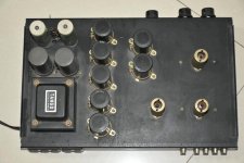
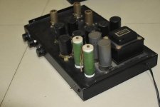
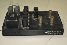
Thorens td 124 clean up and lubrication

I'm about to undertake a restoration of a Thorens td 124, and had some questions:

1) how to best clean painted chassis. I've used warm, soapy water, which got rid of most of the gunk, but some still remains. Made the unfortunate mistake of using laquer thinner, which removed some paint. Luckily, the test spot was under the platter, and won't show. Any ideas for getting it clean enough to apply wax? Ran out of SimpleGreen, but I think I'll get some more and give it a try. Also, how to clean the unpainted bottom of the chassis? I know it won't be seen, but since I probably won't do another complete teardown for years, want to make it shiny and new.

2) Cleaning motor cover plates. I've seen pictures of others restorations, and the before and after pictures were remarkable. I don't know if they were replated, dipped in carburetor parts cleaner, or what, but they looked like they just rolled off the assembly line. And how to clean the rotor--Kerosene, parts cleaner, naptha?

3) Cleaning and polishing stepped pulley, motor wheels, spindles, etc.? Will metal polish, such as Maas, be sufficient?

4) Cleaning and lubing linkages. Was again thinking of metal polish, and once they're clean, using Superlube with teflon, and 20 SAE motor oil for all bushings.

5) Polishing main bearing. Even though this turntable is from about 1959, I honestly don't think it had ever seen any use. The main bearing looks perfect, not a mark on it. Checked it with a dial caliper, and can't find any wear. I mean not even .0001 of an inch. Think I'll polish it anyway, just for ***** and giggles. Bushings also look perfect, but I bought some replacements anyway.

I got this TT on craigslist a few years back. The owner was asking $1200 for a complete deck, with an Empire tonearm (minus cartridge). Thought I'd take a chance and gave him a lowball offer. He at first declined, but then called back and said he'd accept the offer of $700.
I've seen complete beaters with frozen motors and missing parts sell for twice that. Low serial number model, in nearly pristine condition--very happy he accepted!! When I went to pick it up, I discovered that this guy was uber rich, and had a 5 car garage filled with cars, motorcycles, and hundreds of pieces of stereo equipment. He was moving, and couldn't take all of his stuff with him, and just wanted the turntable to go to someone who would appreciate it. Score!

Orion HCCA 2100

When I got this amp in to repair the guy stated it blows the fuses .

I replaced the fuses and powered the amp up and it idled perfectly and had clean audio .

I removed the clamps and noticed someone tried repairing this at some point and it has mismatched power supply fets and outputs .

All power supply fets and outputs test fine .

Im going to replace all power supply fets and outputs due to them being mismatched .

Wondering if this could cause the fuses to blow in the vehicle or anything I should check ?

HLCM - Horn loaded compact monitor

In pursuit of pure playback realism and a system that has low compromise in in-the-room tone and presence I will document my mistakes here in this thread. The goal of the horn array is to have no hesitation in believe ability when listening to a good recording. I find from the upper bass up must be front horn loaded, otherwise it just sounds like a speaker trying to be real paddling away at the room air sounding fake. Horns move the air needed for the human to be fooled into experiencing realism. The system is made to fire down the long walls of my rectangular concrete bunker and sits on carpeted concrete slab. The system is made to work with the room.

Here is the in room response of the low midrange and upper bass (heart of the system), one channel 15' away at the listening position. Here is where most of the music lives and this compact horn system is built around this range first. This range consists of two parts, one the B&C 8pe21 in a 46" long front horn with an 8 square foot mouth and 4" throat 120 - 1K range @ 106 db/w/m sensitivity. Two, the horizontal floor coupled line array stands for the midrange horn with four sealed 8" woofers wired in parallel with 103 db w/m voltage sensitivity. These two parts are biamped and the upper bass coupling stands operate 60 to 120 cycles and can be precisely aligned with the 8pe21. If you get this range right you will have a basis for a system with realistic in room sound. The bass modules are high passed 4th order at 60 cycles and operate in stereo. The midrange horns can operate up to 800 cycles realistically.

hornbassmodule.jpg

Does B+ also determine power supply capacitor voltage rating?

Hi

I am trying to understand more about tube amps so I can eventually do some modifications to my own tube amp.

Do the power supply capacitors also need to be rated according to B+? So let's say B+ is 180V, are 180V of current going through the power supply capacitors or does it become 180V after it has already passed through them (if that makes any sense)?

I am in Europe so voltage from the wall would be 230V.

Cheers
Projects by fanatics, for fanatics
Get answers and advice for everyone wanting to learn the art of audio.
Join the Community
507,669
Members
7,883,469
Messages

Filter

Forum Statistics

Threads
405,990
Messages
7,883,469
Members
507,669
Latest member
dukerd74