Intermittent very high pitch buzz

Hello all,

I’m new to this forum and start off with a problem I need help with, so sorry for that.

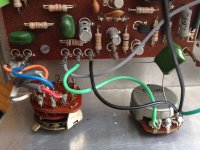
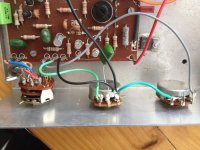
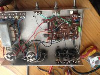
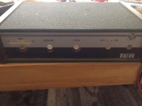
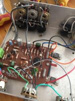
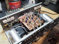
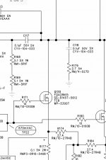
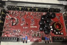
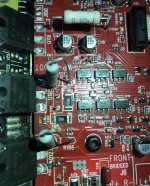
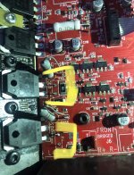
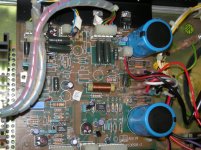
I have installed a sound upgrade in the TT consisting of Hertz 2way in the doors, and a JL audio Subwoofer in the boot. These are running from a 4 channel amp and a mono amp. The source is from Apple CarPlay via a PX6 android unit.

My problem is I have an intermittent very high pitch buzz coming from both door speakers and tweeters. It happens roughly every 20 seconds and lasts for 5/6 seconds at a time then goes away.

The engine needs to be on for this to happen.

So far I have double checked my amps ground, both amps are in a splitter block then a single ground to the chassis.

I’ve unplugged the RCAs from the HU, but the noise remains.

I’ve unplugged the RCAs from the amp, but the noise remains.

Unplugging the RCAs doesn’t get rid of the intermittent buzz, but it is quieter.

the only way I can have the HU on without the buzz is when the engine is off.

I’m out of ideas.

tia

James.

Hornresp, TQWT, MLTL, and WTF

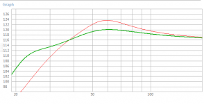
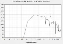
Hello experts. I am learning how to use Hornresp and think I finally have a grip on how it works, at least enough to load a driver, select the enclosure, and mess with the shape and size of the enclosure. I am trying to model a TQWT and MLTL to see if a concept I have is possible. I am unfamiliar with those designs but wanted to venture beyond sealed and BR. I am building a 2-way loudspeaker so the woofer will need to play smoothly up to its crossover point. As I mess around with the cross-section areas, lengths, driver placement, and stuffing, I can't seem to get rid of the (what appears to be) harmonics. If I were building a subwoofer cabinet, I wouldn't care because all the ripples would be above the cutoff frequency.

My actual questions are:

Is Hornresp displaying the predicted response accurately or is the ringing showing up on the graph just noise above a certain point?
Should I be able to see a relatively flat response graph like I would with Winisd?
Are harmonics a function of these types of enclosures?
Is there any other software besides Hornresp to model these types of enclosures?

Thank you in advance!
  • Like
Reactions: emc71

6th order PA & excursion

Hello everybody,

I wanted to design and build a PA subwoofer. I've already build some speakers and got a tiny bit of experience.

I wanted to build a 6th order sub (no particular reason, there just are a lot of standard vented ones(yes I see the hint) and I just wanted something special).
As design software I used http://speakerboxlite.com or WinISD. (similar results)

But I run into one problem: Whatever I do, whatever driver I choose, i always run into excursion problems. And not insignificant ones.
Here for the RCF LF15G401 we have multiple times xmax.
1652627852787.png


Is that a Problem? How do I select a chassis for a 6th order? Or is it just dumb to build?
As a target for this project I wanted to build a sub to play -3 from around 33hz (so I'm ok with a loudness penalty for playing deep).

If you read this far, thank you so much for your time already 🙂

new Aleph P1.7 finished - some afterthoughts

Hi all,

long time since I posted something here, but reading a lot!
I was working on a P1.7 for 4-5 months (afterhours), to drive a Aleph 5 I built the year before (balanced).
I am not at all an electronics engineer, just an 'interested' hobbyist and trying-to-be-a-smart-guy.

This Aleph5 is such a success in building and sounding I thought this P1.7 would be easy-peasy.
However...

Building a power amp is really simple comparing to a preamp. You put in a signal, and you hope it comes out amplified and sounding at least better than what you had before, with just a power button that stops it from doing that.
A preamp however, there is a smaller amount of amplification to do, with smaller signals, relative to that noise is bigger. So there's much attention to grounding to be done. You also want to switch inputs, mute while switching, choose a volume. And find out a way to control all of that, by means of knobs, IRremote and maybe even bluetooth and/or rs232 (i'm a home automation engineer). You want it to trigger poweramps, and because everything Nelson Pass designs needs hours of warm-up, you want to time that to make the max of your precious listening time. There are different psu's, voltages to work with, for control, relays, etc... Meanwhile, you want to have it look the part to impress non-audiophile/electronics friends, and while at that control an old but very very good design very 2022-ish.
A preamp is not just an amp. As I read it elsewhere, it is the centerpiece of all your equipment.

So I ended up soldering the amplification part, psu's I found pcb's for, but (as I can't design my own pcb's) also break my head around the relay-volumecontrol, input selection and then the whole control part of that. I had to write C++ code for the first time in life, which I liked very much, see the above 2022-ish approach.

I made a lot of stupid errors, as well as real beginner-errors. I managed to make a real nice (almost-finished) case. I ended up with 'the thing' on the pictures below. It is not completely finished, but I've had it for now, just some details.
It is working and sounding just incredible, comparing to what it replaces. The image is much wider, but maybe not as deep. Dynamics and transparancy are really remarkable. Sometimes I find it to sound 'flat', or with some sort of 'sawtooth' in it. Have to resolve that.

Things that concern me:
  • It has 3 balanced inputs, and 3 unbalanced, of which just one is working, not in a hurry for that
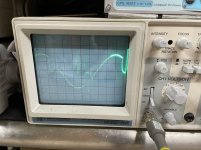
  • My scope showes an output that is not correct, but the scope is even older than the P1.7 design and in bad shape... I will break my head over that in short future. If the amp would sound as the the scope image looks, it wouldn't sound at all.
  • Further software writing, that freaking C++ language, to implement a lot of things, of which timed start is most important to me (or the home automation control part, even more work).
  • Finding/calculating a nice volume lookuptable, to have less but more meaningful steps.
  • Allthough not critical, the fets get hotter than expected. All are mounted to the same piece of aluminium (not a heatsink, just a thick alu profile). There's a temp sensor in that as well, showing 50°C after 2hours on-time. From then on the sound is best and doesn't get better anymore.
  • I find it to sound slightly better with balanced sources (my CD-player and phono preamp), even when matching SPL as good as possible on ear.

And then just one or two real questions concerning gain:

The lowest gain setting is what works best for me. Then i use low attenuation levels (high volume setting), being able to max it out. It is really loud then but speakers can have more (they are only 90dB). The higher gain setting is not workable, as the lowest volume setting is still to loud then. Is there some advice for that?
That working unbalanced input is used for a dac. As being just theory: it sounds 6dB quieter than balanced inputs. I'm working with an extra relay that grounds IN- when an unbalanced in is selected. What's the best way to match this volume level to the balanced ones?
  • can I switch input gain at the same time, with relays, while it's on? I guess so. But: -6db for unbal, then from 1,3 to 9,7 will make it sound louder than balanced.
  • is it better to calculate (in software) a 6db higher volume setting, and applying that without being visible to the user (which is me offcourse ;-) ) Then it would max out earlier.
  • As I'm using a modest Chord DAC, i can but didn't try to crank up the output from 2V to 3V. There's no own volume control on the dac. How many db does 1V mean then?

So this is a lot of text, I guess every thought of the 4-5 building months are spit out.
All in all, this was one hell of a project, for the unprofessional me which I am.

Mr. Nelson Pass: thank you a lot for bringing me all this incredible and affordable sound quality, but above all and most important albeit maybe unintended, all this acquired knowledge. (I am addicted to tech knowledge of all sorts. For that and the fun of it, in my younger days I took a car and engine completely apart and remade it but better, stronger, safer and faster, only to understand how cars work).

Also thanks to this wonderful forum and offcourse its users!

Regards,

Dieter
IMG_9340.jpg

IMG_9294.jpg

IMG_9289.jpg

IMG_9282.jpg

IMG_9263.jpg

67484947722__C29949B1-C10F-4F8B-BB19-F9ECEF1BCA1A.jpg

Large ES-horn prototype

Some time ago, I had a 1" horn designed by Joseph Crowe - as large as possible if printed in 4 pieces on my 3D printer. I never got beyond some test prints and the printer is in a never-ending upgrade process. Since I have bought some 1.4" exit drivers meanwhile, I scaled the model 1.4x and modified a bit for layered CNC construction. For the test, I went on the cheap side using 15 mm OSB flooring panels. The dimensions are 725 x 300 x 380 mm (WxHxD). I have 20 layers cut, glued in pairs ready for 3D machining. I just tried to lay the parts on the CNC in the correct order and it looks pretty impressive. Heavy as hell, too. This piece serves like a learning object to get some machining skills for fabrication of such large horns.

Attachments

  • 2CADAE59-6BBD-4686-A129-59DB4E16B1D8.jpeg
    2CADAE59-6BBD-4686-A129-59DB4E16B1D8.jpeg
    493 KB · Views: 213
  • 0D6C34E6-E193-4144-8223-E44E94B0A8EE.jpeg
    0D6C34E6-E193-4144-8223-E44E94B0A8EE.jpeg
    398.8 KB · Views: 222
  • D5882212-ABA7-4A63-97AB-EBF816171428.jpeg
    D5882212-ABA7-4A63-97AB-EBF816171428.jpeg
    297.4 KB · Views: 207

Finding my way around 1.4 in / 3 in VC Eighteensound compression drivers

Some of this was discussed by others in this thread https://www.diyaudio.com/community/threads/18-sound-nd3st-compression-driver.300974/
but in its five pages, it meandered off. It was triggered by the Voice Coil review that showed extremely low distortion and good CSD of the ND3ST. Someone suggested that maybe it was measured at lower than stated 104 dB / 1 m, measured with the microphone 10 cm from the mouth of the horn. First of all, the fundamental level in the distortion plot is only roundabout 107 dB (as compared to ~126 dB for the NSD1095N measured a few years earlier under the same nominal conditions), and then the drive level to achieve 104 dB / 1 m was given as only 0.42 V for the ND3ST (and 2.2 V for the NSD1095N, both being 8 Ohm models). A 4015 series driver also measured in Voice Coil was similar to the 1095 in terms of sp in the distortion plot and drive voltage.

Ok, with that out of the way, I found 7 ND3 and 3 ND1460/80 drivers and compiled their key data and impedance and FR plots. I may have missed other 1.4 / 3 in drivers in their huge catalogue. Edit: I missed the ND1460/80A.

Attachments

  • 18sound_3in_pt1.PNG
    18sound_3in_pt1.PNG
    1.4 MB · Views: 331
  • 18sound_3in_pt2.PNG
    18sound_3in_pt2.PNG
    744.4 KB · Views: 303

Motional Feedback Dipole Subwoofer with a current amplifier?

A new thread is created:

MFB and CFB using Piratelogics Electronic​


After have been experimenting a lot with MFB in the 90ties i went to dipole subwoofer and QUAD electrostatics.
Now i want to add accelerometer motional feedback to the double Dipole woofers.

And after reading some papers
http://rmsacoustics.nl/papers/whitepaperMFBtheory.pdf
http://rmsacoustics.nl/papers/whitepaperMFBdesign.pdf
Read BOTH!

I realize that i also need current feedback power amplifiers.
There is other threads about the MFB itself. Want to know if anyone tried or want to try the combination of:
1. Accelerometer feedback
2. Current feedback amplifier
3. Dipole long throw subwoofer
(4. Chip Amp) not neccesarily.

Signal conditioning:
15 OP amps/channel is needed since im stupid... :-( ?
3 OPs 6order low cut 16 Hz filter
2 OPs for Linkwitz transform Q value compensation
1 OPs for Dipole correction
2 OPs for LP filter at 200Hz
1 OP amp for 200-300Hz notch filter (extending the phase margin) reed the papers linked in the first post.
1 OP for current feedback loop
1 Op for impedance conversion of the accelerometer signal (buffer) on the speaker frame.
3 OPs for acceleration feedback signal conditioning.
1 OP for signal blender between signal Input and acceleration feedback.
2oct 2020. I ended up with keeping my MTAudio active crossover, includes dipole compensation, and for MFB section i use one double 5532 and some FET transistors/channel!

I will use 3*Dayton IB 15" drivers per side. They work in free air.
And i will use ACM-01 as accelerometer, and only one accelerometer/ channel wich means that one out of three woofers will have the accelerometer.
The other two elements will have added mass matching the accelerometer setup.

And each element will have it´s own current feedback chip amp. This will guarantee same excursion on each element!!
Or i could build a more powerful amp and put each element i series. Also this will guarantee same current (from the current feedback amp) into each element.

But thats not my problem now. I want to know how to reduce the nr of OPamps.
20 dec 2019 Update:
I added a magnet to the polepiece and gained 1.1 dB in sensitivity that means that the 200w chip amplifier get an extra "boost" of 60 watt to 260watt (for the same sound pressure), to do the calculation you can use this calculator: SPL Calculator i know you can´t hear 1.1dB increae in sound pressure but my brain knows that i´m better off then original! 🙂

2 oct 2020, Almost there... see distortion figures #27
Specially thanks to: rscamp, chriscam, bolserst and joe rasmussen

Too much gain

Hi, I am have had this clone Preamp built up board for a while & although it sound very good I cannot overcome the gain of the unit, It is just to high to early. I have now tried a 50K pot (that is what the original was, or so the label said) 100K & 10K & the result is the same for all. I can only get to a 9 'o' clock position & the vol is to high.

can anyone advise how the effectively reduce the vol. I have heard you can do it with resistors, but am not sure how to accomplish this.

Cheers for any replies

Chartwell PM110 Speakers - Crossover Help

Hi I am a complete DIY aoudio novice who needs some help.

I have been given a pair of Chartwell PM110 mk 2 speakers (early 1980's) which have not been used for many years and which I would like to refurbish. I have tried the speakers and they work though bass seems to be some what lacking, I was thinking of attempting a recap but need some help identifying parts. Can anyone tell me if the 5 Rifa brand silver rectangular capacitiors in the below photo are bipolar electrolytic and if so are there modern equivalents available of similar dimenions that would easy to fit on the board? Also the 3 black resistors are covered in white powdery deposit, is this normal with resistors of this type or does it mean they have failed and need repalcing?

PM110Crossover003.jpg


Sorry if these are dumb questions🙂

Cheers
Rich

Yamaha DSP-AX750se........Dead, No Power

Hi Everyone,

Was wondering if someone could help me as I'm either missing something obvious or having a stupid moment.

Have just got a Yamaha DSP-AX750se surround amplifier that I'd like to repair, I bought it faulty thinking it would be something obvious.

Plugged in and switching it on, nothing happens, the unit is completely dead.
Took the lid off, and looked for signs of a component blowing. But all looks fine.

Took some measurements AC in is fine, but there is no AC out to the transformer. Believe the fault to be in the Sub Trans area. Investigated after obtaining the service manual and a few of the voltages are missing.

Have the service manual, if someone would be willing to point me in the right direction. Or am I in the wrong area all together.

Never worked on a 8.1 amplifier before so all help would be amazing 🙂

Pictures and service manual on request 🙂

Topology choices- help me decide

Im trying to figure out what the best arrangement is for the simple circuit of opamp> diamond buffer global feedbackback headphone amp.

The psu i have ready is lm317/337>capmx build, adjustable from +/-24v downward.

Id like to feed the headphone amp at +/-24v, running the diamond buffers at that voltage and then knocking down the rails to +/-14v with simple resistor+ zener shunt for the opamp.

Or i could run the whole headphone amp at 14v and skip the added complexity.

My question is what will be the pros and cons of the 24v version besides complexity? With the diamond buffer at 10v higher the psrr and headroom will increase. But would the extra resistor and the zener used for the shunt degrade the psu or make it better? I can see how the ripple would be smaller with the added reg but the impedance and the noise will be higher?

First Watt F5 - PSU Build - Advice needed

I got interested in DIY audio a little over 10 years ago. Around that time I came across the First Watt F5 and got hooked on building it. Where I was it took me some time to get boards, components and heat sinks. Then life happened and it all got shelved. Life has now un-happened and I am looking at finishing this old project.

I still have the components from then, including 10+ year old Rubycon 15000uf 63V capacitors. They look physically good and seem to test fine using a multi-tester, just wondering if it would be fine to use them given they've not been used at all for so long.

I damaged a few in de-soldering them from a partial build, scoring the outer cover. I can fix the damage using heat-shrink tubing and/or electrical insulating tape - would that be OK?

I'd acquired PSU boards at the time but now realize that they only allow for 30mm dia capacitors, while I have 35mm dia capacitors. The solution to this is,
1) Put four under the board and four above. I don't think electrically this would be a problem. Not sure about the look or if it affects the board mechanically. I would use a 160mmx120mm aluminum sheet under the capacitors bolted to the board and on spacers so the capacitors are not sitting against the enclosure. Still have to build that, so no pics of that.
or
2) Buy new capacitors. Right now I can get capacitors from Cornell-Dubilier.
or
3) Buy the PSU board from diyaudiostore.

With delivery to South Africa, option 2 and 3 are about similar in cost. I've attached pictures of the damage to the capacitors and the layout I mentioned in 1.

Any suggestions/advice is most welcome.

IMG_3753.jpg
IMG_3755.jpg

FS UK: 3x 600W Torroids (massive and heavy) Linear PSU boards and Power Amplifier stages

For sale,

Parts removed from various Denon AVC amplifiers (AVC A10SE and A11SR x 2)
Amplifiers were decomishioned for various reasons, all these parts were 'known good'. The aim was to build some power amplifiers but I won't have time for decades so a chance for someone else to acquire some great quality gear.

Included:
One linear PSU stage from A10SE - not sure if this board has all the regulators and diodes on it or just caps
One linear PSU stage from A11SR7
two sub power boards with smaller transformers from A11SR (power for digital electronics)
3 torroidal PSU's, 2 matching one visually different.
one 5 channel power amplifier from AVC A10Se
Two amplifier strips from A11SR.

Voltage of PSU's was about +69V/0/-69V if iirc.

Plenty here to make some very nice amps.

Any questions give me a shout.

Looking for £200 for everything inc. postage to UK. No international sales due to weight and hassle.
Payment by Paypal for goods and services. Will be VERY well wrapped.
Due to the nature of what is being sold I will need you to demonstrate some simple electrical safety before completing the sale, not being facetious; I don't want anyone to zap themselves unnecessarily.

thanks all.

Attachments

  • IMG_20220130_114733.jpg
    IMG_20220130_114733.jpg
    507.8 KB · Views: 191
  • IMG_20220130_115017.jpg
    IMG_20220130_115017.jpg
    313.8 KB · Views: 164
  • IMG_20220130_115044.jpg
    IMG_20220130_115044.jpg
    351.4 KB · Views: 166
  • IMG_20220130_115051.jpg
    IMG_20220130_115051.jpg
    435.9 KB · Views: 174
  • IMG_20220130_115110.jpg
    IMG_20220130_115110.jpg
    356.2 KB · Views: 161
  • IMG_20220130_115225.jpg
    IMG_20220130_115225.jpg
    454.5 KB · Views: 167
  • IMG_20220130_115319.jpg
    IMG_20220130_115319.jpg
    491.3 KB · Views: 175
  • IMG_20220130_115543.jpg
    IMG_20220130_115543.jpg
    554 KB · Views: 180

For Sale in UK; ±12 VDC Regulated Linear Power Supplies suitable for Opamps etc

I have a large number of thorlabs ±12 VDC Regulated Linear Power Supplies, product page here:

https://www.thorlabs.com/thorproduct.cfm?partnumber=LDS12B

These are designed for use with APDs, very sensitive light detectors that have been used for things like getting audio from a power LED on a laptop by sensing the variations in intensity and outputting a waveform. Needless to say that device needs a very clean power supply to work.

These retails at £65.51, I'm selling for £20 each, but have a large quantity so discounts on multibuy.

UK post or collection from Oxfordshire only.

Can my DMM measure ripple?

I was hoping to compare PSUs.
I found you can measure ripple with a DMM.
But when I read up on it, some say you can, some say you can't some say it depends, some say it is more complicated than that.
But i don't understand the reasons.

I have an Aneng AN870:
https://www.aliexpress.com/item/33004463675.html?spm=a2g0o.order_list.0.0.b1c11802kFg5wk

First thing is to find whether mine is able to.
it states True RMS.

New FIFO buffer for RPI/SBCs

Hi ,

in the past few months we have worked very hard on a new shield for RPIs/SBCs.

Basically the main idea belongs to Ian's. His hardware is actually superior to ours , mostly in the way he implemented the clocks and to the attention of the detail (like mounting xtals on a pcb supported by elastics ). So we credit Ian's idea and his great design.

Our hardware/soft is not a copy , its an implementation of the same idea. We use a FPGA and sram to buffer the DATA and we reclock bclk/mclk outside the FPGA using NDK (or Crystek) . The board has an eprom but its not HAT complaint (because of the space). FCC will be available for the board.

Main reason for making the board was to try to correct the audio clocks of SBCs and bring high quality audio to anyone that has an SBC around..for a great price.

Attachments

  • Kali1.jpg
    Kali1.jpg
    654.3 KB · Views: 7,169

Krell KSA-80 protection circuit settings/questions

Does anyone on the board know how to set up the Krell KSA-80 protection settings dipswitch? I have tried several times to get some answers from Krell, but I get no response. I have a set of Kappa 9's that I use it with, and I will occasionally put the Krell into protection if just the right bass passage hits. I have heard there was a modification to make the amp stable with Apogee Scintillas, which can present the same sort of difficult load.

Thanks in advance for any infrmation.

Best regards,

Switching 12V power supply

Hi everyone, before anything else, I would like to thank you for your patience with me.

I would like to build a basic audio project. The idea is that the finished product should sit firmly on my office desktop, have 2 ~20W coaxial speakers as a primary output. To drive that I'm planning to use 20W class-D Adafruit amp . There will be several audio inputs, two line-ins, arduino-controled FM radio, and a bluetooth receiver. Beside the speaker amplifier, I thought it would be nice for it to also have a CMoy headphone amp.

So far I wasn't able to figure out how to choose the right power supply. It's gonna be 12V @*~4A, with some step-down regulators where needed. From what I read so far, I should not even think of using switching power supply, but I've never held soldering iron in my hand so I don't really feel like building my own linear PSU. So SMPS it is, as it is a first project it does not need to be perfect on the first try anyway.

The thing is how do I choose the power supply? From what I read, the supply needs to be regulated (most of them are, ) and more importantly isolated. This is where I get really confused. What do I really need to look for? Should I look for class II supply, or is class I sufficient, or are these markings irrelevant to me? I was looking at MEAN WELL GS60A12, which is a class I supply, and MEAN WELL GST36B12, a class II adaptor. Then I saw a supply designed for hi-fi appliacations, SMPS-86, which uses MEAN WELL IRM-45-XX modules.

So, my question, what do I choose? Am I on a completely wrong track? Can I use the adaptors above without getting (too much) noise, and which one? Or should I use the class II module, and if so, can it be used as it is? Or is it necessary to build/buy a more sophisticated circuit? Or should I stop worrying because from I described above, it won't really matter anyway? 😀

Thanks very much...

Question regarding Common Drain OPS cross conduction

Hello everybody,

I have a question regarding common source Amplifier outputs. As these have thier sources at thier supply, even a small ripple in the supply voltage causes them so conduct more. This does not produce an output signal however as the NFB of the amplifier corrects the Offset and centers it.

The same cant be said for the cross conduction that is happening. As the Feedback loop does not see the current between the Mosfets when its not producing an offset voltage, this causes the bias to drift and also causes heating of the Mosfets due to several amps cross conduction. I made a MWE of an OPS/VAS to illustrate my question*:

Unbenannt1.PNG


V7/8 simulate 1 V of Supply ripple. Without a feedback loop this causes a massive Offset of over 9 V. The lower fet ceases conduction completely

My question is now, how is this adressed in an Amp? I did not find many amps that use this ops and only one by Nelson Pass mentioned that it needs a regulated supply. Are there other methods for preventing cross conduction in this principle? Is this the reason why its so seldomly seen? Is this topic discussed elswhere? I had a hard time finding annything on that.

Thanks for your time and have a nice day =)

*as I said just for Illustration I do not intend to use a 2N2222 for a fet driving stage...

Attachments

Seeking PSU Schematic for Goldmund Nemesis 3

Am servicing a Goldmund Nemesis 3. Only have the amplifier schematic, but not the schematic showing the relays.
The unit powers on, but when taking it out of standby, a relay behind the front panel chatters at 60Hz. I suspect a bad cap somewhere that drives the relay coil, but can't see anything due to the way the PCB is sandwiched as part of front panel. Does anyone know physically which capacitor is responsible for filtering the power to the relay coil?

PNP Bipolar Transistor Single Stage "Direct Couple" 300B

Recently I have a idea of PNP transistor "direct couple" 300B grid.
PNP hfe is around 100 so it may be a candidate of 300B's single stage driver.
I build my circuit on bread board and do some measurement of sine ware 20Hz ~ 20KHz.
I choose 24931 PNP transistor which has max Vce 250V.

Attachments

  • OPRC1992.JPG
    OPRC1992.JPG
    243.9 KB · Views: 362
  • KHQQ1473.JPG
    KHQQ1473.JPG
    336.9 KB · Views: 349
  • PTKS8295.JPG
    PTKS8295.JPG
    333.7 KB · Views: 364

Unknown vintage output transformer 15k:600

Vintage output transformer - from memory, this was salvaged from a pro tape recorder (early transistor era) so probably has decent frequency response. Shielded enclosure (soldered). With the following markings:
1594I, 73-4-2
Primary 15,000 ohms @5mA DC
Secondary: 62.5, 150, 250 or 600 ohms

Any known circuit designs out there calling for a transformer like this?
Can this transformer be directly coupled with a tube output stage (e.g. 12AU7)?
What else might it be good for?
Can it handle balanced I/O (given the separate shield terminal)?

Any suggestions -- tubes, circuits, topologies -- would be appreciated. Had this for a long time, I'm weighing up whether to finally build something simple and straightforward, like a microphone preamp, or sell it on.

Attachments

  • IMG_0881.jpg
    IMG_0881.jpg
    388.2 KB · Views: 108

Help with Linn Valhalla - I think it is just the switch, how to bypass?

Hello I just purchased a used Valhalla power supply for a DIY project. I like the idea of it. anyway I plugged it in and no motor spin, no LED on the switch.

I went through the basic trouble shooting ensuring I had 300v DC of C1 and the usual suspect of resistors read the correct value. I was about to move onto the some of the smaller electrolytics but before doing so I checked the switch ( the seller didnt originally give me the switch but did today when picking up another part.

The switch and the ribbon cable stay open circuit when pressed. All 3 connections to each other. I therefore think the switch is broken ( it can happen )

Can anyone guide me what pins to short out on the board to test this theory and see if the motor spins up? i think shorting pin 4 & 5 should do what I want but i would like to check.

Thanks

Chris

Attachments

  • linn switch.PNG
    linn switch.PNG
    54.3 KB · Views: 185

DIY Toroid Winding Machine

I'be been researching making toroids (painful!).

It seems that every DIY design of a winding machine uses the same design - a single ring and a spool/bobbing on the driven ring. Yet this is possibly the worst way of doing it.

The professional machines have two independent rings. This has two effects (a) the laying can be kept precise and to a specific tension and (b) the rate of spooling varies as the rotation moves around the toroid which is enabled by the slipping differential of the second 'spool' ring to the speed the wire is being drawn by the primary laying ring.

Only when loading the windings on to the spool ring is the spool ring locked to the primary driven ring. The needed amount of wire is drawn onto the spool ring. The wire is then threaded into the primary laying ring and the lock between the two rings is disabled. The primary laying ring then lays the wire and the second spool ring is then simply keeps up by the pull of the wire and friction providing the tension of the wire.
This technique allows for off centre winding and for non-linear winding such as 1/2,3/4,5,6/7,8,9/ or progressive winding by dynamically reacting to maintain the set tension.

I thought about the way the rings should be - the primary ring has a U cross section whilst the spool has a reverse L with a plastic slip ring to allow the primary to pull the wire off at any point around the diameter as it rotates but not scuff the insulation varnish off the wire.
The friction could be made by either the power ring sitting on the spool ring or the spool ring sitting on the power ring. Both rings are kept steady by wheels on the outside edge.

This means the laying can be via a plastic/teflon V shaped wheel.

Lastly the toroid can be held by three or four wheels with one powered by a stepper motor or better still each wheel being geared/belted together so that as the motor moves all provide a rotation. If you wanted to be smart then an optic camera with flow control could see the movement vs the rotation commands sent to the stepper motor.

Has anyone tried to make this style of machine?


* Naturally for safety using a pre-built professional mains toroid then stripping off the secondaries would be an option.

EDIT: Sorry - wrong forum, can a friendly mod move it to the construction tools forums please 😀

Can you check this schematic.

Does this circuit have any kind of speaker protection. And if so could you explain it.
While testing a new speaker the speaker shorted and after that one chanell is dead. (Back to square one for me). It was a 250 watt speaker. But locally made.
If this thing has no speaker protection I think its time to bin this amp and just build something with Mosfets / transistors that way the parts are easy to get and replace.
Im on a low budget and plan to continue running crappy locally made speakers. That is not going to change.
The Left channel has stopped working. Again lol.

Attachments

Bluetooth vs HDMI, whose DAC is it, or what does Apple TV actually do?

I have a basic conceptual confusion as to what is going on when streaming music to my home theater receiver. Both my Apple TV and laptop are connected to the receiver through their own HDMI ports.

1. What is Apple TV sending to my receiver? I assume it is digital data that the receiver's DAC and subsequent Codac's decode and send out to the amplifiers.

2. But, is there a difference in the digital data sent from the Apple TV to the receiver when the controlling source is from my cell phone, iPad, laptop? That is when I use AirPlay to choose Roon or Tidal content through the Apple TV.

Does it make a difference if the receiver is getting data directly from the Apple TV or is using Airplay from my iPad to the Apple TV?

3. There seems to be better fidelity, higher quality sound, streaming Tidal when I use my laptop connected to the receiver through HDMI directly. It sounds different when I use Airplay through the Apple TV. I am unsure why this would be the case. Isn't data data?

Ortofon AS-212 and Audio Technica AT33PTG/II

A couple of weeks ago I posted a question regarding the above mentioned cartridge. I was planning to use it with a new Sorane TA-1 tonearm.

Unfortunately, the Sorane costs more than expected. I found an Ortofon AS-212, it is made in Denmark, please see factory specs.

I have no idea if I can use it with the AT33PTG/II which, according to Jeff, Vinylkid58, is of medium compliance or buy an Ortofon cartridge. Please note that I am not familiar with the new line of Ortofon cartridges, I had two MC30MKII approximately 20 years ago, but I am open to suggestions.

https://www.ortofon.com/as-212-vintage-p-653

Horacio

Sphinx Project 12 MK2 service manual

Does anyone have the service manual specific to the mark 2 model? I can only find mark 3 manual online.
Mark 2 only has balanced input (no RCA input).
Otherwise what would be helpful is high res pics of mark 2 components.
My plan is to bring these amps back to factory specs. Someone has been in there before me and it doesn't look all good to me (very bad soldering work)
Thanks in advance.

Best way to power this amp?

So, I've bought a TPA3116 based chinese AMP.

This is the model: https://pt.aliexpress.com/item/1005003406991503.html?spm=a2g0o.productlist.0.0.7a793b88DFQFQ8
It is a 5.1 AMP, rated at 50W per channel and 100W for the sub, although I will probably not hit 50W on every channel (except the subwoofer) as the room is quite small (10ft x 10ft) and at max volume it would probably be pretty loud at that listening distance, but I still want to be able to hit it.

Now, I don't know how to power it, as I can't find linear power supplies that offer that kind of power (at reasonable prices), and switching power supplies that supply the required 24v 10-15A are usually symmetrical, and I don't know if they can be used on this AMP, probably not.

I do have a computer PSU that I can buy a Step-up boost converter to step up 12v to 24v, but I don't know if that would be the best way, if there are any cons (other than possibly inaudible noise).

Any ideas?

How do I attach this volume knob?

Hi

I had to remove the volume knob to remove the volume control from the chassis.

Now I don't understand how I can mount that volume knob again. It just doesn't "click" it just spins on it's own, I made a small video, it's just easier than explaining.

Login to view embedded media
I had someone else try as well and he couldn't figure it out either.

ty very much

Attachments

  • 1653588553159.jpg
    1653588553159.jpg
    154.6 KB · Views: 110
  • 1650135176035.jpg
    1650135176035.jpg
    169.4 KB · Views: 119

Increase gain World-Design KT88xl

I have a World-design KT88 XL, The input level (sensitivity) with my Panasonic UB9000 media player is great, but the input from my Xiaomi mi box is really quiet and I need to turn it up nearly all the way to great a resonable volume when streaming video. Is it possible to increase the gain, just a little, without messing up the sound and stability?

A copy of the schematic is enclosed.
kt88.jpg

Line level to mic level to record

I have a digital piano and it has a ear phone output where I can connect a simple ear phone (like picture below) and it works fine. However I would like to connect this ear phone output to my smartphone jack (TRRS - GND, MIC, Left channel and Right channel) in order to record what I am playing. So I need to bring line level down to mic level, using a 1000x voltage divider. I hope the picture below helps:

Using the circuit below, my smartphone is recording the sound fine and it looks good. However when there is nothing being played in the piano, I hear a buzz/hiss sound which is pretty annoying in the recording. So what should I do to solve this problem? I tried replacing the voltage divider from 33k/33 ohm resistor to 10k/10 ohm resistor (still 1000x reduction), but the buzz/hiss is still there.

NOTE: when I connect my ear phone to the piano, the sound is crystal clear, no buzz/hiss even in the loudest volume. So I am pretty sure something in the simple circuit above is causing this problem.

NOTE (2): sorry if I posted in the wrong section, I didnt find a better one than this.
Attachments

  • imagem.png
    imagem.png
    17.9 KB · Views: 107

New TSE-II build has higher than expected B+

Hi, I just finished building a TSE-II amp. Parts include:
Edcor XPWR131-120 PT using the 330V taps
C-14X choke
Toroidy TTG-KT88SE OPT using 3K
Raytheon 5842WA tubes
Psvane HiFi 300B tubes
Chinese 5AR4 rectifier - test tube
All standard components from the BOM + 100uF motor run cap

Yesterday I went through the Checkout procedure and set the tube bias to 61ma. It plays and sounds good. Not as much volume as expected, but that’s maybe my crappy test speakers. However, I’m worried about my running voltage readings:
B+ 424V
B- -258V
Wall outlet is 117V
Edcor PT 660V red/orange tap putting out 679V to board - a bit high
R 5842 set to 173V
L 5842 set to 174V
L 300B set to 61ma
R 300B set to 62ma

The B+ looks to be too high to run 300B tubes for any length of time, so I shut it down after 15 minutes even though the tubes weren't glowing at all. I have the standard 47uF 500V cap for C4. Isn’t B+ of around +375 better for the 300B tubes longevity?

I boosted the bias on the 300B tubes to 70ma, but B+ didn’t hardly go down any. So, would lowering C4 to a 4uF – 10uF range lower it enough?

Any thoughts would be appreciated, thanks.

Mike

Seeking Direction and Knowledge

20220512_225151.jpg
I recently acquired a U.S. AMPS amplifier model KA100HC rev.1. It's nothing like I've ever seen. Information on the web brings up very little and what does come up doesn't match either the name, model, or description. I'd like to find the true specs and if it's worth resto, bring it to working order. In not saying it doesn't work though because I've hooked it to a 12-volt source and the red light did come on, but that's as far as I was comfortable with going. I have a bunch of pics and am available to take more and to try to answer any questions you may have.
Thank You
20220512_224505.jpg

Attachments

  • 20220512_225306.jpg
    20220512_225306.jpg
    503.3 KB · Views: 106

Volume control in tight space, parallel potentiometer?

Hello,
I'm trying to add physical volume control to a Nokia N-Gage console.
I've decided on a wheel like gameboys have.

The main issue is how to wire it up due to space and construction constraints.
I will place the wheel in the same plastic part that the speaker is seated in.
See below the speaker and the red circle being where the wheel would be seated in a slot I will cut.
The speaker prongs push against pins in an intermediary part that in turn push onto the motherboard connectors.

Ideally I would like my wires to stay within a single part of the device so I'm not messing with floating wires.
So my question is: Can I use a potentiometer in parallel between the two speaker prongs to reduce the volume and not burn anything out?

Alternatively I would probably need to run two wires between the plastic part with the speaker to the motherboard where I would interrupt a trace to put it in series.


diagramaudio.png

Hello from Utah!

Hello everyone!

My name is Jason from Pleasant Grove, Utah. I am a computer programmer by day and a classical guitar builder by night. I just finished my first speaker build and I had so much fun that I have a sneaky suspicion it won't be my last. I'll post the details (including all my "learning" experiences) over in the loudspeaker forum.

Until next time...
Jason

For Sale Audio Note AN-E L speakers

For sale Audio Note AN-E L speakers. These are from 1999. new drivers and foaming from 2020 and upgraded connectors. I am selling them as I am getting new AN-Ks that suit much better my new smaller listening room.

they sound amazing and in great shape. wood colour shows their age but other than that they look perfect and come with their original grills. Delivered with diy stands which are exact copy of the AN UK ones.

selling for 1500 euros. Pick up in Belgium. I cannot ship them as I have no boxes.

I will post pics once back at home at my pc.

Class B + Technics class AA sym Armaghedon

As a continuation of my Germanium foudation Ch1 headphohes amplifier I tried even more simulations around a circuit that is intended to incorporate the Technics class AA buffer which I have tried in the past for headphones amplification and I/V conversion.I modified the original values of the Technics net so that the distortions got a little bit better and it happened that I had a lot of those resistors lying around.
You have essentially two variations A and B based on noninverted and inverted op-amps structures .While the noninverted structure can lead to lower distortions the inverted structure looks more stable with less compensation.If you wish to check some more things you have also the asc files. Ufortunately the only final transistor models that allow for such low distortions were the mje15032/33...but I have better transistors than all my ltspice sym library.If i get 1/th of the simmed performance I'll be utterly happy.Besided the first 4 trasistors , as some of you know will be...germanium trasistors, of course🙂
I already start building the inverted B balanced variation. The unusual choice for the 2k61 resistors was made just because I found some Dale resistors looking too sexi for my project.

Attachments

  • B1K15V8ohmunbalanced.png
    B1K15V8ohmunbalanced.png
    41.9 KB · Views: 209
  • B10K15V8ohmunbalanced.png
    B10K15V8ohmunbalanced.png
    41 KB · Views: 236
  • B10K24V8ohmmynet.png
    B10K24V8ohmmynet.png
    48.9 KB · Views: 228
  • B10K24V2ohmseries.png
    B10K24V2ohmseries.png
    51.2 KB · Views: 230
  • B10K24V8ohm1W.png
    B10K24V8ohm1W.png
    51.6 KB · Views: 181
  • B10K24V8ohm.png
    B10K24V8ohm.png
    51.3 KB · Views: 183
  • B10k15V8ohm1W.png
    B10k15V8ohm1W.png
    50.6 KB · Views: 173
  • B10K15V8ohm.png
    B10K15V8ohm.png
    46 KB · Views: 163
  • B10K15V4ohm1W.png
    B10K15V4ohm1W.png
    50.8 KB · Views: 161
  • B1K15V4ohm.png
    B1K15V4ohm.png
    51.4 KB · Views: 164
  • B1K15V4ohm1W.png
    B1K15V4ohm1W.png
    49.6 KB · Views: 160
  • B1K15V8ohm1W.png
    B1K15V8ohm1W.png
    49.7 KB · Views: 150
  • A1K15V8ohm.png
    A1K15V8ohm.png
    46.7 KB · Views: 153
  • A1K15V8ohm1watt.png
    A1K15V8ohm1watt.png
    47.3 KB · Views: 148
  • A10K15V8ohm.png
    A10K15V8ohm.png
    48.8 KB · Views: 138
  • A10K24v8ohm1watt.png
    A10K24v8ohm1watt.png
    46.1 KB · Views: 136
  • A10K24V8ohm.png
    A10K24V8ohm.png
    46.2 KB · Views: 141
  • A10K24v8ohm1watt.png
    A10K24v8ohm1watt.png
    46.1 KB · Views: 167
  • B10K24V2ohmseries.png
    B10K24V2ohmseries.png
    51.2 KB · Views: 198
  • unbalanced.asc
    unbalanced.asc
    7.6 KB · Views: 124

3-way with KEF coax "sp1753"

Perhaps starting in the wrong end of a loudspeaker design/build 🙄

Did a first anodizing test of an aluminium ring for my KEF sp1753
Alloy, current, temperature, time, concentration of battery acid etc all have an effect of the end result of the anodized ring, the result wasn't too bad. Maybe not the best looking colour combo 😉

If I go for a Kef Blade/LS60 look-alike design it will be a totally different looking "waveguide"

anodized_gold.jpg
Better looking with a black driver (double sided tape on my KEF R3)

anodized_gold_R3.jpg

Sourcing DIY turntable parts.

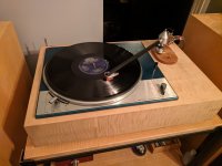
I am considering trying to build my own Turntable. The arm is easy with, but where is good place to find motor, spindle bearing, sub platter and platter?

I could just by an upgrade spindle bearing/sub platter kit like this ( https://www.acoustand.co.uk/collect...ter-upgrade-for-pro-ject-xpression-turntables ), but annoyingly, these have nearly tripled in price in the last year or 2... I could also buy a matching Acrylic plater.

I see this on Amazon https://www.amazon.com/Vbestlife-Turntable-Recorder-mounting-Turntables/dp/B084G2W85H But I am hoping there are better options... the wiring diagram is also above my head (without studying it more)

My plan for a plinth is this https://www.amazon.com/gp/product/B01L5NQ6MQ I already have one I use as a TT base. It is about perfect size wise for me.

The only other question is the belt and speed control. Either I assume you either have variable speed, or Fixed speed with the right size size pulley.

Thanks

Scan-Speak 18W/8545K00 and D2905/970000 2-Way Project

This project started because I had a brand new matched pair of the Classic Scan-Speak D2905/970000 tweeters. I wanted to pick a worthy woofer and considered the following:

Audio Technology C-Quenze 18 H 52 17 06 SD - Probably the best 7" midwoofer ever made, but I didn't feel that $500 a piece was justified for this project.

Scan-Speak Revelator 18W/8531G00 - Great on paper, but maybe too lively. Seems like giants such as Sonus Faber and Goldmund have reverted back to using the Classic Scan-Speak product range.

SB Acoustics Satori MW16P - Heard amazing things online, but...

Scan-Speak Classic 18W/8545K00 - This monster has everything going for it and from recent auditions of Sonus Faber's Guarneri Evo, Futura, and Aida, I can say without reservations that the midwoofer is pure magic. Goldmund also uses a Kevlar variant of this midwoofer (8546) in their Epilogue and Logos 1N speakers.

I will be modeling two projects below and would like to get some opinions on which path to take.

The first modeling job will be of the Sonus Faber Guarneri Evolution clone, since I've practically deciphered their entire crossover from pictures. The Guarneri Evo uses a Scan-Speak 18W/8545K00 midwoofers and D2905/970000 tweeters crossed over at 2.8kHz and tuned to Fb of 43Hz.

The second modeling job will be of the Goldmund ProLogos ($38,000!) speakers. They too use the Scan-Speak D2905/970000 tweeters, but supplement them with dual Audio Technology 18H's. I have the official Goldmund crossover for the 970000 tweeters (crossed at 1.8kHz), but will have to model my own filter for the 8545 midwoofers.

Some pictures of the Guarneri Evo's and ProLogos':

Attachments

  • ProLogos.jpg
    ProLogos.jpg
    195.4 KB · Views: 2,035
  • ProLogos 2.jpg
    ProLogos 2.jpg
    281.7 KB · Views: 1,703
  • ProLogos 3.png
    ProLogos 3.png
    301.2 KB · Views: 1,817
  • 37.png
    37.png
    703.7 KB · Views: 1,779
  • Guarneri Evo.jpg
    Guarneri Evo.jpg
    6.8 KB · Views: 1,731
  • Guarneri Evo 2.png
    Guarneri Evo 2.png
    613.9 KB · Views: 932

Recommend an active crossover (self build)

Not much out there but I've looked at:

Active crossover DIY PCB, 2-way, 2nd order stereo or 3rd,4th mono | eBay

and

ESP Electronic Crossover

I've owned two commercial active crossovers in the past. One was horrible (the net effect was worse than obtained from a modest passive set up) and the other one was stunning, giving the advantages one expects from an active system. The good one (Linn "Aktiv") was a fixed slope LR, with user adjustable gain for each driver. It also had EQ specific for a particular set of drive units, but, as a novice, I should probably keep things as simple as possible.

If someone could look at the above kits and recommend one over the other that would be great, and/or recommend another option.

Need recommendation for 10 inches full range drivers.

Hi, I just bought some old speakers from someone in Perth (currently in transit to Melbourne where I am) and these are old sharp cd-k7000 monster speakers, pls see a YouTube video of these speakers where someone has shown how these drivers actually look like, imo they look ok but these are old and I think these are woofers and not full range speakers, I bought these for a few reasons, first I've been wanting to make something (with 10 inch drivers) for a long time, and the required amount of woodworking for the boxes was giving me the nightmares, I wanted something nice and full for my tube amp (which i'll be buying this year), so when I saw this ad for $20 bucks I knew I wanted these, cosmetically these are good and well made boxes, I'll play these speakers and i doubt if i am going to like 'em, I would want to put in full range 10 inch drivers in these boxes.

so please, recommend me 10 inches full range drivers, total budget for 2 drivers = $200-$300

Login to view embedded media

Attachments

  • maxresdefault (1).jpg
    maxresdefault (1).jpg
    164 KB · Views: 384
  • maxresdefault (2).jpg
    maxresdefault (2).jpg
    115.2 KB · Views: 242
  • maxresdefault.jpg
    maxresdefault.jpg
    120.9 KB · Views: 391

Kef LS60 clone?

I love the design that the Kef LS60 has.
What do you think about making a copy with other drivers.
A full range driver and 1,2 or 4 bass drivers.
Prefer not to have active speakers but completely ordinary ones.
I want a small baffle and a small full range driver. Max diameter 4-5 inches.
The bas drivers should not be larger than 5-5.5 inches and preferably go deep.
Feel free to receive tips on suitable FR and Bass drivers.
Thanks.

KEF LS60 like speaker build

Hi.We want to build a speaker like KEF LS60 with my friend. It is very WAF speaker and i liked the design a lot too(wife fall in love 🙂 .Altough i built a similar design and sound is very very good (i attached in picture ) i want to build like KEF because it looks better.
Which woofers can we use ? It should not be same as KEF. Maybe we can use bigger woofers to get better bass too. (but i want to make back to back woofers but i do not know which woofer will be good) Please advise.

Attachments

  • 20220519_215313.jpg
    20220519_215313.jpg
    419 KB · Views: 268
  • kef ls.jpg
    kef ls.jpg
    34.7 KB · Views: 240

First DIY build decorating some old Def Tech BP-6Bs

First, a little history... About 20 years ago I purchased a set of Def Tech speakers (BP-6B front, BP1.2x surrounds, ProCinema C2 center, ProSub 1000). I have really enjoyed these speakers which I powered with Pioneer Elite receivers (several models over the years). However, I recently switched to a Marantz SR7015 which gave me a couple more channel possibilities to create an Atmos setup. What I really wanted to do was to had some height speakers to the tops of my BP6s, but the speakers were so old that Def Tech doesn't make an add on module for them and I was unable to find a commercial speaker that I liked that would fit on the top since they have a rather small footprint.

So, I had and idea... I am pretty handy in the workshop so I knew building a speaker box would be a no brainer, but I wondered if anyone made a speaker kit with electronics. After a two second internet search I found the DIY speaker community and fell down the rabbit hole! I started looking for a kit I could modify and I eventually settled on the Continuum II by Jeff Bagby. I knew that the box I would need to build would be smaller than Jeff's box, but looking at the specs of the AC130-F1 included in the kit, I figured it would work with a little loss of bass response. This didn't bother me since the intended use was an Atmos height module and frequencies lower than 100hz would not be ideal anyway. So, I decided to jump in and bought the kit. Here goes...

tempImageoHEqqT.jpg
tempImageTCwL81.jpg
tempImage6k6Qha.jpg

I used MDF for the construction of the box. I have a love/hate relationship with that stuff. Shapes well, but makes a huge mess. The box needed to match the dimensions of the top of the BP6 speakers which was 7x11 inches. I didn't want it to be too tall, but the Dolby patent suggests that they should be above listening height but not higher then half the height of the room. Go figure. Anyway I settled around 10 inches high. In hindsight I probably should have gone one more inch to add some more volume to the box, but oh well. The Dolby patent also suggests an incline angle of 20 degrees, but I saw on several forums that people would get better results when they increased the angle of their Atmos enabled speakers, so I chose 22.5 degrees. This also seemed to fit better with the geometry of my room. Plus the extra couple of degrees would also help if I changed my mind and mounted these on the wall.

tempImageSGuEjg.jpg
tempImageuQm9QY.jpg
tempImageG8N2Qe.jpg

Since I wanted these to be a sealed box (just like the Continuum) I decided to add a bit of a rabbet/rebate to help with sealing the corners. I also cut the top angle at 15 degrees to help encourage the signal to shoot up toward the ceiling instead of going forward. And, yes, the tweeter is mounted in front. This will also help if I change my mind and make this a wall height speaker putting the woofer closer to the ceiling.

tempImage3ctLOb.jpg
tempImageHY9mZi.jpg
tempImages4voJo.jpg

Did I mention that I have a love/hate relationship with MDF? Well, I coated the whole thing with epoxy resin (alcohol thinned) to seal the whole thing before painting. This will also help hold the screws better when mounting the drivers. After some primer and some gloss piano black it should match the BP6s quite well.

tempImagez2NlHy.jpg
tempImagefcA1iv.jpg
IMG_2879.jpeg

Since this was such a small box the only option I had was to mount the crossover on the bottom baffle under the tweeter. I got a kick out of testing the speakers. It's always a thrill when a project comes together. For those who have gotten to this point and are curious, that is a picture of my daughter throwing the world's worst tantrum at her grandmother's house in her nice Sunday dress. It was so over the top I just had to snap a picture. She is 27 years old now and is still embarrassed.

IMG_2881.jpeg
IMG_2882.jpeg

And here is the final product! It attaches to the top of the BP6s like it was made for it. Oh, wait... It was! I ran the speakers as my main front channels for a day or two and when coupled with my ProSub 1000 they sound wonderful! I can only imagine what they would sound like in a proper sized box. They are a little harder to drive than my BP6 but I was expecting that since they are in a small box and the sensitivity of the drivers is a bit lower. I calculated that they would probably drop off around 95hz or so, and sure enough the Audyssey room correction software set their crossover at 100 and boosted their level 5db

All in all I was happy with my first build. I learned so much about box construction, crossover design, driver specs, etc. And I have so much more to learn.

Thanks for listening! Until next time...

Jason

Sound Digital 3K Evo D1

Hello everyone
I’m working with this SD 3K. Here is the problem with this amplifie. it came to me with a broken speaker connector
but after I resolder the connector I found out that the 10ohm resistor the is in series with a 470nf capacitor at the
output filter circuit was getting red hot, but if cheat the amplifier to come On without the rectifiers and use a 30 volts power supply
as a replacement for the rail voltage the 10 ohm resistor don’t get hot and the amp plays. any suggestions?
Thanks in advance.

Attachments

  • DE44E5E0-2849-405B-A902-536C42C054A1.jpeg
    DE44E5E0-2849-405B-A902-536C42C054A1.jpeg
    441.1 KB · Views: 93
  • E0CFD7DA-52FA-4FA9-9BDB-90BAB0C5CAC8.jpeg
    E0CFD7DA-52FA-4FA9-9BDB-90BAB0C5CAC8.jpeg
    496.3 KB · Views: 103

Soundigital 1600.1 EVO 1ohm, no ps drive

When I got the amp I found the 10ohm resistor feeding the ps gate driver burned open and the gate driver bad/shorted.

Replaced resistor and chip (UCC27528, afaik an acceptable sub.. original was ucc27524dsdr), still dead.

I have drive from the pic to the driver ic (or at least bursts on each side as it tries to boot), but nothing coming out of driver ic. Seems like I'm missing something silly but...

Supplies are ok at the gate driver.
5v supplies are ok at pic.
Bridges seem fine.
Ps fets and gate resistors all seem fine.
Output section seems ok.

Weird..

Amp blinks 9 times during boot fyi. Never draws more than about 200mA. I've tried 14.4 and 12.4v supply.

Help with crossover, urgent, PLEASE!

I have got a pair of two way speakers with a problem. The crossover is a extremely simple - woofer is connected directly to the terminals and tweeter is connected via a simple RC filter. The problem is that some genius have fiddled with the tweeter filter/crossover and it's not working. The tweeter elements are ok, they show 4ohm and react to the 1.5V battery test. But components in the crossover have been rearranged or maybe something was even added.

What I have are three components - one 3.3uF/700V (made by SCR Silver Sound) capacitor, one 7.5 ohm resistor (marked with North R10 7R5 1304) and one 2.7 ohm resistor (marked with AchrOhmiC 2R7 16W 2%). Impedance of the tweeter is 4 ohm and the speaker impedance should be 8 ohm.

Someone tried to be creative and re-soldered some of the components. There is no measurement between plus and minus tweeter terminals but the tweeter itself measures 4 ohm and seems to be in order even when tested with a battery.

Can someone arrange these components correctly in a simple schematic?

Thanks in advance!

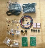
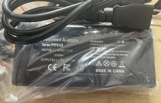
Two power supplies to a molex

I want to use two seperate linear power supplies to feed the 5v and 12v lines of the second power input of an ASUS STX II. (Four, actually)

For those who don't know, the STX II has a second molex power input for a cleaner power supply.

When looking up what colour wire is for the 12v and which is for the 5v I found that connecting both makes 7v.

Will using two different power supplies on the second input work? Or is there something special about PC power supplies that this solution needs and doesn't have?

Attached is the cases for the cards and the two power supplies.

Attachments

  • IMG_20220521_155425.jpg
    IMG_20220521_155425.jpg
    508.5 KB · Views: 139
Projects by fanatics, for fanatics
Get answers and advice for everyone wanting to learn the art of audio.
Join the Community
507,641
Members
7,882,254
Messages

Filter

Forum Statistics

Threads
405,945
Messages
7,882,254
Members
507,641
Latest member
Gousty