JBL M2 DIY Plans Search

Hi everyone,

I've gotten a great deal on JBL M2 parts.
Therefore I'm looking for plans or construction drawings from people that have already made clones.
I've tried messaging Cyril on youtube, POS, PBN Audio, and Leslie on audioheritage.com. I've also found an account I believe belongs to Leslie on AVS Forum.
But I haven't gotten any replies.

Do you happen to know either where there are plans posted, have a copy, or could get me in touch with anyone that has plans?


Thanks advance.


Niclas

Threshold Stasis 5.0 preamp

I bought second hand this great preamp. Great on vinyl, not so good on digital stuff, so I will keep in my analogue set up
The seller sent a universal remote that did not work.
I have asked threshold for the hex codes so I can organise a remote, but they have refused!

This is the most unhelpful reply anyone might expect from a supplier - Threshold.
Do they deserve any loyalty?
"Thank you for your inquiry. We are not allowed to give out such information. That is a company policy. "

Good grief.
Can anyone assist?
I also have two s1000 monobloc amps which are superb

Basically
Products = great
Management = crappiest of crappiest

Cambridge Audio Azur 640A Protection Mode

Hi folks,

Per headline My 640A has refused to turned back to normal playing mode from the protection mode. I tried cutting it off to all power for a few days, which always did the trick until this time, then eventually this morning I disconnected it from everything but it still won't turn back on. I am going to assume that something inside has busted.

Anything else you can recommend to try without opening the thing up before taking it to a repairman or looking for a new amp?

Thanks!!

What did you Catch & Release today?

I go on the hunt occasionally and sometimes I stumble into some Audio thing that, even though I pass on it, may be of interest to others here. If only a picture for bemusement, that's OK too. - as long as it's something you had in hand but passed on.

I can start with an ebay link for a pair of Peavey SP3's. Love, love to have 'em, but...they're on the east coast. Seller even gave me a 10% discount too! https://www.ebay.com/itm/194489164157

QUAD ESL 57 A little work on the loudspeaker

I decided to make some refurbishing regarding one side of my ESL speakers.
These will include experimenting with a set of unarced 'NOS' treble panels removed from an old QUAD, vacuum out, 'wash down' and redoing the dustcovers on all the panels, doing some paint repairing, and changing the diodes on the HT unit if necessary.

Photos are of the transformer successfully removed from it's box and my recently acquired 'untouched' panel.


An externally hosted image should be here but it was not working when we last tested it.


An externally hosted image should be here but it was not working when we last tested it.


An externally hosted image should be here but it was not working when we last tested it.

Peavey CS4000 DDT light on

Good Day All. I have in front of me, a Peavey CS4000 that had a previous attempted repair but has no output. One parallel bank of 4 outputs were replaced with the original parts, but 2 gate resistors have been replaced with outboard mounted ones as the package size is unavailable locally. The amplifier turns on, but the only light that is on is the DDT light on both channels. It is making rail voltage, and there is no significant DC voltage on the output terminals. Can someone help me troubleshoot this amp and its DDT protection circuit. Thanks

Attachments

  • IMG_20220105_083910.jpg
    IMG_20220105_083910.jpg
    488.4 KB · Views: 1,083
  • IMG_20220105_083928.jpg
    IMG_20220105_083928.jpg
    520.8 KB · Views: 538
  • IMG_20220105_083945.jpg
    IMG_20220105_083945.jpg
    445.3 KB · Views: 497

Rockford Fosgate M400-4D

Hi guys
Today I received this amplifier to repair, in which "someone" has put his hands to try to repair it ...
As you can see in the first photo, five electrolytic capacitors were completely loose from the motherboard (these capacitors had lost their capacity and are swollen)
There are also some components that have been replaced by other dubious features ...

All the base plate is covered with a special varnish, which makes it difficult to read almost all components ...

Does anyone know of a scheme?

Attachments

  • DSCN4126.JPG
    DSCN4126.JPG
    825.7 KB · Views: 314
  • DSCN4128.JPG
    DSCN4128.JPG
    715.6 KB · Views: 290

Music and Mic on a PA?

We are using a 30 year old PA system at our rocket launches to announce flights and for safety and information announcements.

We would like to be able to play music, streamed via bluetooth from various members phones.

What we want is, when you pick up the microphone and turn it on to make an announcement, the streaming music is paused until the mic is turned off. There are many people that work the launch control and we need this to be very simple.

Our mic and the PA system uses the 6.3mm single channel jacks for input and output.

What can we get that would allow that functionality?

Thanks...

Jeff

FS. Chiarezza speaker kit from Rick Craig (Selah Audio)

It was suggested (at ASR) that I should post this here.

As much as I hate to do so I'm listing this speaker kit for sale. My health and financial situations make it highly unlikely I'll be able to build/own these myself in the near future.
Here is a link (via wayback machine) of the kit listed on Rick's site.
It may have been his last design 😔
Chiarezza Speaker

The kit is brand new and complete, having been unboxed when it arrived and to take pics recently. I'll be posting them shortly. It's been stored properly the rest of the time.

Anyone living close enough to pick up could get a bonus of 3/4" and 1/2" (real) Baltic birch. Enough to complete the speakers with thicker walls/baffles than the original plans called for.

I'd like, of course, to get back the kit cost but I will let them go them for 2500 + shipping.
That's approximately the cost of the drivers alone.

Thanks, T20220512_151732.jpg20220512_151635.jpg20220512_151524.jpg20220512_151510.jpg20220512_151304.jpg20220512_151243.jpg20220512_151154.jpg20220512_151058.jpg20220512_150949.jpg20220512_150910.jpg20220512_150750.jpg20220512_150709.jpg20220512_151809.jpg

LL9202 for 46 driving a 46

Hello, I am trying to understand how to choose which of the secondaries to wire up for the LL9202 output transformer for use with a Type 46 tube. My understanding of magnetics is minimal and I am really missing the presence of Kevin Carter from K&K. Does anyone have an idea for which of the secondary formats would be best, A through E? I ordered the LL9202 for use with a 6.5K primary (SE) and 8 ohm speakers but the options presented do not speak to me for best service. Help Please!

Thomas Mayer, if you're out there, I am Sure you know how to make this output transformer operate at its best in this situation 🙂

Attachments

Background noise on guitar amp TD35

Hi,
I am trying to restore an old Crate TD-35 based on a 12AX7 preamp and a transistor stage powered by TIP120/125 (see my old thread on the restoration http://www.diyaudio.com/forums/instruments-amps/228959-crate-td35-fixing.html)

I think the amp got exposed to too much humidity and there were a few things to change.
Since I've got the amp I made the following changes :
- recap on the two main caps
- changing the output resistors
- changing all jacks connectors which seemed oxidized
- changing the two output transistors with a TIP121/126 couple

For now everything seems to work right and the sound is good but I have a terrible background noise and I really do not know where to look. Here is what I can say about that:

- the noise is only present when the cable is plugged but I have tested the cable and the guitar on another amp and they seem fine
- the noise seems amplified with the High potentiometer and the Reverb potentiometer and the High pot cracks a little
- the sound is really attenuated when the tube channel is selected and for what I understand about the schematics, the high pot is connected to the other channel but the reverb is connected to both channels
- I have tested every ground and each connection is good and even the star ground which is done near the input jack
- I have tried to replace the High pot (250k) with two resistors (100+150k) to simulate its action but the sound was still here
- the sound is not present in the line out and between that and the headphone/speaker output there is the transistor stage with a bunch a transistors that I did not all try but the most part seems good

So I am looking for an advice if someone had a similar problem or if someone can tell me what can be the cause of this noise (a bad cap, a bad resistor or transistor or something else)

thank you guys

For Sale London UK: Several EL38 types, some rare

Selling a number of EL38 types, some rare. All tested good. I used these in triode in a 2 stage SE amp with DHT drivers. The gain is around 15 in triode.
Great sounding tube - much better to my ears than 6L6, EL34 or any of those types in triode. Priced as shown.
EL38 Cossor £18
EL38 Mazda x2 and Dario £38 SOLD
EL38 Mullard in original box £18
EL38 Philips x2 £36 SOLD
EL38 Mullard x4 £48
EL38 Mullard x2 £28

Send me a PM or contact me directly at performanceandmedia@gmail.com. Andy


EL38 Cossor.jpgEL38 Mullard new.jpgEL38 x4.jpgEL38.jpg

Attachments

  • EL38 Mazda + Dario.jpg
    EL38 Mazda + Dario.jpg
    461.3 KB · Views: 99
  • EL38 Philips x2.jpg
    EL38 Philips x2.jpg
    874.3 KB · Views: 100

Technical chat with David Bosch - Kef R&D Engineer - about loudspeaker design, IMD, and more! 💡💡

A few things up front that I need to mention to ward off any negativity:
1) We had some streaming glitches. I mention this at the front of the video. I wish it weren't the case but such is life sometimes.
2) I don't monetize these videos so before you complain about ^ just remember that you're not paying for this and I'm not making a dime from it.
3) I like to keep these as "discussions" and NOT "interviews" (which I also mention in the video).
4) There are websites that can do transcriptions if you don't want to listen to this. You'd have to Google for them because I don't use them myself.

Okay, I hope you all enjoy and find it insightful as much as I did. And, if you don't mind, please leave a "thank you" to David for taking time out of his day to join me for such an open chat.

And if someone out there wants to make some timestamps notes, let me know what they are and I'll add them to the video. 🙂

Login to view embedded media

Capacitor Help - Acurus DIA-100 Amp

I have a 26 year old Acurus DIA-100 amplifier and I am considering replacing the 2 CDE power supply filter capacitors. These caps are 18,000uf, 70V and an odd size at about 44mm in diameter and 95mm long. I'm having trouble finding replacements that will meet the voltage requirement and also fit the space; 70V is an uncommon value and the newer 75V and 80V caps that are available are too large in diameter at 50mm to fit the space.

The power supply is 60V unregulated, 63V caps would fit but I'm not sure this leave enough margin for voltage fluctuations, could use some advice on this.

Another option would be to use a bank of smaller capacitors in parallel mounted on on circuit board like this one and tucked in where the current caps are. Would there be any issues using a bank of capacitors? I know it'll lower the ESR, which seems like a good thing but want to make sure it won't cause any unwanted side effects.

I could try to shoehorn the larger, modern filter capacitors in between the transformer and the amplifier boards but it seems kludgy and I'd prefer to make use of the space that's already there.

Any advice would be much appreciated.

Attachments

TV rectifier diodes for power supply

Got a bunch of TV EHT rectifier and damper diodes here.
What kind are the most suitable for a power supply?
Ive got heaps of DY 802 and DY87, etc but it looks like they dont handle alot of current. I have some EY series damper diodes too.
Ive seen somewhere a pair of TV diodes used on a project but cant remember the type. Either way, its worth me keeping some for future if they are decent spec and is a cheaper option than going with GZ34 or other large rectifier tubes.

Am wanting to build an amp with 2 pairs of 807 in class AB and am looking at options for a decent tube rectifier that can handle enough current, looks like I will need at least 300mA.
Any part numbers to look out for would be great, ive got a few tubes to go through here. Winding a custom power transformer is not an issue if its got a 1.5V heater.

Ltspice "armchair design" and insides into sloppy PCB design

Thanks to PMA remarks I thought of launching a subject on trying to simulate audio amplifiers from a pcb designer perspective.It might have been analysed somewhere else, but I'm not aware of it so let's get started:
As I'm not really a professional in LTspice simulations , the only tool I know to make a quick check on stability and performance including the pcb design skills is using the cshunt .option. From what I could see, the default settings in Ltspice approximate a .chunt value of 1e-15 which is basically ideal while a true very high quality pcb would be approached by 0.5e-12...1e-13 farrads with a mean average of 1e-12 for sloppy designs and I put togeter a collection of simulations to show the differences that this simple cshunt directive brings into the game. There are simulations done on 2 ohms load, 1khz and 10 khz with 3 values for cshunt and 4 values for the bode plot.Obviously 1pF capacitance between every nodes being the worst nightmare.It can be seen if you bother analysing my printscreens that a 0.5pF difference means around a full order of magnitude in distortions at 10 khz while just about 4...5 times at 1 khz which is kind of predictable . A full picofarad difference can mean a lot more though.
I'd be really thankfull for some other insights like other directives or techniques to simulate the worst case scenarios from a pcb designer perspective and also how to prevent them in the real design.
I myself don't make any pcb design currently and I'm all into solderable pcb breadboard as I can fly wires over any two points avoiding a lot of trouble.I avoid smd components as much as I can and usually i doVERY fine with breadboards that offer lots of me stitching vias to isolate ground loops by design.

Attachments

  • your usual crappy simulation with no cshunt option.png
    your usual crappy simulation with no cshunt option.png
    79.2 KB · Views: 292
  • fantastic pcb design.png
    fantastic pcb design.png
    93.9 KB · Views: 220
  • Good pcb design.png
    Good pcb design.png
    26.8 KB · Views: 192
  • slightly sloppy pcb design.png
    slightly sloppy pcb design.png
    27.9 KB · Views: 190
  • sloppy pcb 1e-12.png
    sloppy pcb 1e-12.png
    30.3 KB · Views: 174
  • V3 NO Cshunt option.png
    V3 NO Cshunt option.png
    36.6 KB · Views: 189
  • Bode 2ohm NO Cshuntoption.png
    Bode 2ohm NO Cshuntoption.png
    26.7 KB · Views: 162
  • Bode 2ohm 1e-14.png
    Bode 2ohm 1e-14.png
    20.2 KB · Views: 157
  • Bode 2ohm 1e-12.png
    Bode 2ohm 1e-12.png
    18.9 KB · Views: 149
  • V3 10K 2ohm 1-12.png
    V3 10K 2ohm 1-12.png
    43.3 KB · Views: 170
  • V3 1k 2ohm 1e-12.png
    V3 1k 2ohm 1e-12.png
    45 KB · Views: 177
  • V3 10k 8ohm 1e-12.png
    V3 10k 8ohm 1e-12.png
    43.2 KB · Views: 160
  • V3 1k 8ohm 1e-12.png
    V3 1k 8ohm 1e-12.png
    40.5 KB · Views: 158
  • V3 1K 2ohm 0.5-12.png
    V3 1K 2ohm 0.5-12.png
    46.7 KB · Views: 171
  • V3 10K 2ohm 0.5-12.png
    V3 10K 2ohm 0.5-12.png
    40.5 KB · Views: 145
  • V3 1k 8ohm 0.5e-12.png
    V3 1k 8ohm 0.5e-12.png
    41.1 KB · Views: 185
  • V3 10k 8ohm 0.5e-12.png
    V3 10k 8ohm 0.5e-12.png
    37.3 KB · Views: 145
  • V3 1k 8ohm 1e-13.png
    V3 1k 8ohm 1e-13.png
    43.5 KB · Views: 156
  • V3 10k 8ohm 1e-13.png
    V3 10k 8ohm 1e-13.png
    41.4 KB · Views: 144
  • V3 1k 2ohm 1e-13.png
    V3 1k 2ohm 1e-13.png
    45.6 KB · Views: 225

Anyone able to help with speaker purchase in The Netherlands?

Looking for a member in The Netherlands to help facilitate a purchase of some speakers in Maastricht. I have an account on Marktplaats and have purchased from it in the past. But now they added a second verification step that requires a phone in the EU. Alas...I'm in the US so I can no longer access my account. Hopefully it would as simple as facilitating communication between me and the seller.

Send a PM if you might be able to help. Happy to return the favor w/ a US purchase!

Using the QUAD II's without the QUAD 22

Dear Forum,

I am asking, what are the most important arrangements to use the amps without it's preamp?
I found these probably suitable to directly hook them up with my DAC's RCA output.
I have to buy an another set of Bulgin power plugs, and earth the chassis, too, but I could use the existing one from the 22's

I read somewhere, that there is no DC coupling cap at the signal input of the II's, that one's should think about of.

What do you think?

Is it mandatory to have a preamp, or would the DAC's output enough?

Thank you for your help in advance!

Cross Talk/Noise on Turret Boards

Hello, this is a question about a random thought I had.

Can Turret board construction cause more cross talk and noise than point to point wiring or PCB? I know the turrets are typically several mm apart, but all of the components carrying the signal are typically mounted in parallel to each other.

Any thoughts/equations to help me think about this concept more thoroughly?

Heathkit AA100 troubleshooting

Hi everyone.

I am working on a heathkit AA-100, wich is a 7591 push-pull integrated. It has what sounds like a 120hz hum to me, on both channels (I compared the hum to 60hz and 120hz tones from a generetor app in my iphone). I suspected the filter caps in the power supply so I replaced those with new JJ multi section electrolytics (They fit the original holes perfectly, really satisfied with that). There was also a paper 20uf cap that I replaced with a new 20uf electrolytic, one resistor that was directly on the cap was replaced too. The 20uf cap has a selenium diode and a resistor in parallel with it so I replaced the diode with a 1n4007 and I changed the diode that’s in series with it for a 10k instead of the 8.2k that was there originally to compensate for the lower resistance/higher efficiency of the 1n4007. There was a paper/wax capacitor between the fuse and the ground so I replaced it with a film cap of the same value.

so from now that’s all I’ve done to it, but the hum is still there. It’s a bit better now but still not usable. When there is no input, the amp is practically silent and I can get the hum pots to lower the slight noise to a satisfactory level, but as soon as I connect my phone in the aux in and start a song, the hum is there. Also, when I did my tests after replacing the filter caps, the amp lost all its bass and I never came back since. I tried other inputs. All the tubes tested very good on my eico 667 tube tester. The power amp section has been recaped by someone else before but I can’t confirm that it ever worked well after that since the owner bought it as is.

what could cause a total lack of bass on both channels ?

since the hum is 120hz and present on both channels I suspect that it’s caused by the power supply, but nearly every cap in the supply is new. Do you have any idea as where I should start looking ?

thanks a lot !

Attachments

WAW Idea and Question

Hi Folks,

Ive spent some time looking at the ideas and projects with the WAW concept. Since being recommended it on another thread. I have an Idea. I want to build a speaker with an 8 inch full range ( likeing the Lil Audio speakers at the moment) and an 8 inch subwoofer. crossed at say 200 hz

My question is, I'm not sure how to even model this much less the physical config. How do a figure the size of the box with 2 drivers?

My initial thought is a speaker on top of a tall rectangle cabinet and a sub on the bottom. Is this even a realistic Idea? I'm not exactly sure how 2 drivers in a box interact (didn't get that far in the speaker building book) ...

Can anyone shed some light?

TNX
73

Tim

large box of vintage resistors?

Over the past year I've been helping to clean out the basement of a family friend who passed away.
As a former electrical engineer and life long tinkerer he had accumulated quite a bit.
I bought all the cabinets he had there which amounted to several truck loads of 12x8x3" parts bin cabinets from the 1940's or so.
With the bins came the parts.
My interests are much newer and my intent for the cabinets was to use them for other purposes.
After sorting through and bagging the contents of those cabinets, I ended up with about a 15lb box or so of carbon comp resistors.
I see them selling on eBay but have little interest in going through all that.

What is a massive assortment worth? There's roughly 100 to 250 of each value in what i believe are 1/2 and 1 watt values.
Each bin was put in a bag and marked with the value on the drawer label.
Lot size is roughly a box the size of a case of long neck beer bottles or so filled to the top.

Is there any value in these other than taking a $150 offer from some artist who wants them to make jewellery out of them?

Repurposing my old AudioPro T3 (2 Tweeters and a Woofer)

Recently my AudioPro Addon T3 died, but the 3 speakers themselves still work fine. I want to get some kind of Audio amplifier with an aux cable, and wire it back up so I can use the speakers again.

The speakers are two tweeters and one woofer, all 6 ohms.
Currently I'm confused by how to set up the circuit to incorporate the 3 speakers together.
Audio amp boards are either 1 or 2 channel. I'm unsure as to how i'd wire this up to get a good all around sound. Although, I'm not sure if just wiring in mono would sound okay? I've heard people mention crossovers, but not sure how I'd incorporare them

Thank you
Speakers i have :https://www.ebay.co.uk/itm/195089406177?hash=item2d6c3c18e1:g:kK8AAOSw09tikbQf
Board i was considering: https://www.ebay.co.uk/itm/195089406177?hash=item2d6c3c18e1:g:kK8AAOSw09tikbQf

ZM's 2SK2087C musings, phase one (SissySIT as cradle)

Well, as Greedy Boyz did share (tnx!!!!) some interesting info in https://www.diyaudio.com/community/threads/odd-sit-vfet-2sk2087c.385288/ , frenzy is there and who know how it will end

Yeah, impossible to keep low profile, but lets just hope that price isn't going to sky and over

So, officially - parts are Iznogood, everything above 2$/pc is steal and overpriced :devilr:

Anyway, CodyT sent me few, and they arrived pronto

Have some more arriving, sent from friendly Greedy Boy from Japan, but they are still collecting dust in my Customs , that will be covered ( along with my official gratitude) when I see them

pics of package sent by CodyT, along with basic Ugs measurements (Uds 24Vdc, Iq 1A8, Igate~20uA (0mV2 across 100R gate resistor)

more specific info can be seen in thread linked above

Attachments

  • IMG_20220526_131128.jpg
    IMG_20220526_131128.jpg
    84.1 KB · Views: 239
  • IMG_20220526_131200.jpg
    IMG_20220526_131200.jpg
    105.2 KB · Views: 202
  • IMG_20220526_131311.jpg
    IMG_20220526_131311.jpg
    97.1 KB · Views: 216
  • IMG_20220526_131416.jpg
    IMG_20220526_131416.jpg
    96.5 KB · Views: 220
  • IMG_20220526_131432.jpg
    IMG_20220526_131432.jpg
    99.3 KB · Views: 239
  • IMG_20220526_131709.jpg
    IMG_20220526_131709.jpg
    121 KB · Views: 218
  • IMG_20220526_132141.jpg
    IMG_20220526_132141.jpg
    54.6 KB · Views: 232
  • IMG_20220526_200509.jpg
    IMG_20220526_200509.jpg
    90.2 KB · Views: 228
  • IMG_20220526_200519.jpg
    IMG_20220526_200519.jpg
    98.3 KB · Views: 228
  • pinout-and-size-comparison.jpg
    pinout-and-size-comparison.jpg
    107.7 KB · Views: 228
  • Like
Reactions: wangweiliangb

FS USA 2 New BG NEO8 PDR BOTH $150+SHP

Never mounted
$150 for both OBO
PREFER USA Only
Plus you pay for shipping. Use if it fits it ships USPS.


Bohlender Graebener Neo8-PDR Planar Transducer

roduct Details
Brand Bohlender Graebener
Model 111-913205-01
Part Number 264-7541
UPC 848864034461
Unit of Measure Each
Weight 0.95
Product Specifications
Tweeter Type Planar
Power Handling (RMS) 40 Watts
Impedance 4Ω
Frequency Response 700 to 20,000Hz
Sensitivity 92dB 2.83V/1m

Attachments

  • DSC01625gif.jpg
    DSC01625gif.jpg
    349.4 KB · Views: 238
  • DSC01624gif.jpg
    DSC01624gif.jpg
    380 KB · Views: 247
  • DSC01626gif.jpg
    DSC01626gif.jpg
    341.6 KB · Views: 225

Need help with LTspice PSUs CRC filter simulation

I am trying to see the effect of the DC voltage filtering if I were to use CRC filter. I have drawn the simulation, but it does not seem to be working. I also wanted to check on the effectiveness of the snubber capacitors right at the transformer AC secondary coils.

Any help will be greatly appreciated!

Thanks in advance,
Pavlo

Attachments

  • sch.PNG
    sch.PNG
    8.2 KB · Views: 276
  • crc psu.asc
    crc psu.asc
    3.2 KB · Views: 82

DCR, Double chamber reflex

Ok gents, time settle the formula for creating a DCR (double chamber reflex) enclosure, once and for all. Notice that we're not talking about DBR (Double bass reflex) as that is something else entirely (with a confusingly similar name). Creating a DCR is in on itself not particularly difficult. However all discussions and tutorials seems to go full fitness industry mode and no one says the same thing. This is why we need to agree on this once and for all.

I've not built a DCR yet because I don't got the time to find out what all of the parameters on the build should be by my self via endless testing. Using Claudionegro's guide (DCR) goes a long way, but his talk about ports falls short in explaining. On other websites and forums (the little that there is on the subject) everyone has their own interpretation. In addition, the DBR and DCR is constantly mixed. Stirring all the information together, my take on the DCR enclosure so far is:


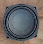
1. Pick a suitable driver of choice (EBP and that jazz still apply).
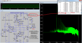
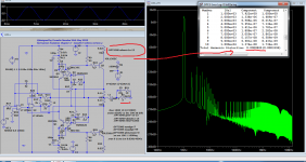
2. Make/simulate a 4th order alignment that fits you liking.
3. Simulate the enclosure from step 2 with two ports. (Keeping max port velocity to 5% of sound speed etc. still apply)
4. Take the enclosure volume from step 2 and divide it into 1/3 and 2/3. Such so the total volume still equals the volume from step 2.
5. Put the port (not total area x length, but the area x length of one of the two ports) you found in step 3 in the three different place that makes it a DCR. (One in each chamber to the outside, and one in-between the two chambers )
6. Place the driver in the larger chamber.


Simple enough, however it is the parameter rules that gets confused. Here is what I think is correct:

A. The port dimensions result is a product of the tuning in the full enclosure (regular 4. order BR), not in any of the 1/3 2/3 divided chambers. (I'm not sure on this one).

B. The driver should always be placed in the larger chamber. (In DBRs it doesn't matter as far as I know.)

C. All the three ports should be of exactly the same dimensions (or at least the same tuning). (I've seen someone say that the port connecting the two chambers should be twice as long as those connecting the inside of the enclosure to the outside, something I think is incorrect as it would throw the tuning of the smaller chamber right off.)

Please add/correct/give idea if you got any.

dcr1.gif


dcr2.gif

Double Chamber Reflex Mark Audio Alpair 10p or 12.2p ????

Hello Members,
I'm pondering a new build but haven't decided what. Here's my dilemma: I have the Alpair 10p in a Pensil enclosure, which I like alot, and the 12.2p in a 19L bass reflex standmount, which I'm not too crazy about. I listen to rock and a bit of everything else except classical. I would like to have a floorstander, for rock, and a bookshelve/standmout, for everything else.
I am really interested in trying Scott's DCR, Juliet(12.2p) or Titania(10p).
Since I listening to a lot of rock, I was thinking of building a SuperPensil 12.2p and compare it to the Pensil 10p and then keep the one that suites my taste. I would then use the other driver in one of the 2 DCRs. Unfortunately not too many DCR using the Mark Audio drivers have been built, so, I would like to pick your brains as to what is my best option based on your experience with the Pensils and the DCRs specs on paper?
Thanks

Where to invest?

I thought some would find this interesting. We are subjected to expert reviews and optimistic specs in glossy brochures but where do manufacturers spend money and where do they skimp when it comes to speaker systems.

Recently I've had occasion to dis-assemble three sets of floor-standing speakers with surprising results. First came the 2-way Toshiba SSPJ1. With a mediocre Peerless SKO165 bass driver a cheap and cheerful mylar tweeter it seems Toshiba spared every expense! This is confirmed by the 12mm MDF used to construct the cabinet. Any bracing was deemed superflouous and unnecessary. Surprisingly Toshiba found some loose change under the sofa cushions to spring for a 12dB crossover.

Sony went in a different direction. Their 3-way SS-MF450H boasts superb build quality, 19mm construction with bracing to boot, any rodent would see this cabinet as a formidable bomb shelter. The bass driver looks like it can handle itself (outperforms the Peerless in the same cabinet) However, the cradle is plastic - not sure if that's a good or bad thing. At this point is where the money ran out. Technically, the SS-MF450H is not 3-way. The budget didn't run to an actual crossover. The mid-range driver and tweeter are protected from low frequencies by a simple capacitor.

Finally, a pair of Eltax Concept 180s found their way to the butcher's table. The cabinet is well constructed, 12mm MDF with the appropriate bracing. Everything, even the drivers are designed to be neat, shiny and pretty. Performance-wise the drivers are crap, Who am to advise Eltax but there's a reason the Concept 180 has reputation for lacking bass. The pre-moulded ports you pulled off the shelf tune the port to 39hz, the driver couldn't get that low if it was equipped with a JCB (Trackhoe). With money left over Eltax, at least installed a decent cross-over.

Epilogue: I got the Sonys for £0.99 because some new-age types had painted the cabinets green - they could never come back from that. I put the Sony drivers in the Eltax cabinets, with the Eltax crossovers.

How many is too many? (mids)

I have been sitting on a large stash of Scanspeak (12MU + 18WU) and RAAL (various) tweeters for close to 10 years now, with the intention of building a home theatre system.

Recently I have come across the Illuminator Centre http://www.troelsgravesen.dk/Illuminator-CENTER.htm Which is essentially what I want to build, but with a RAAL tweeter instead of a Scanspeak one.

Unfortunately I can't just change tweeters and be on my way since the shape of the RAAL in question https://www.raalribbon.com/products_flatfoil_140-15.htm
doesn't really lend itself to a straight swap out.

I could mount the RAAL tweeter horizontally but I fear what that might do to the response. I have a CNC so I could custom make something to mount it vertically.

If I am going to go to the trouble of deviating from the standard box is it worth my while adding more mids to the speaker? Bare in mind this is a centre speaker for home theatre where most of the content coming out of it will be dialog, and the RAAL have a fairly high sensitivity (95dB@1m/2.83v).

I use 2 of the 12MU's in each of my open baffle speakers, but they are open baffle not in a box. Why is it that most speakers only ever seem to have one mid driver?

Is there any reason I couldn't use 2 or even 4 mids (series / parallel) in the centre?

Ill-center-1200-1.jpg

Brand new KT88 - quick 'pop' during warm-up.

I bought a new set of Gold Lion Genalex for my current-production McIntosh MC275. The factory tubes are fine and I wanted to pull and save those (as in, they still work, everything has been perfect with the amp and tubes, not one single issue).

When I powered the new tubes on for the first time, the KT88s made a lot of noise (like the metal heating and expanding...way more than subsequent power cycles) and there was a quick quiet 'pop' from one of the channels about 30 seconds after power on (as I could still hear the metal heating, expanding). I saw a very small blue spark at the base of a tube (specifically the round flat disc at the bottom of the actual insulating spacer...I think that is what it is called).

Everything looks and sounds good.

I got a second (small) pop again today (again, less than a minute after startup) and everything is working fine. I was not watching and not sure what channel or tube it came from.

It 'feels' like there might be some crud burning off vs. it failing but I am not an expert.

Curious if this is normal (or if it goes away, not worry about). Either way, with the holiday weekend and me working from home part of the week, I can put a TON of hours on these. In other words, let them fail if they are going to fail...or see if everything normalizes.

Thanks!

Powerboards? Do they make a difference?

I've added a couple of components to y set-up and I need a new powerboard with 8 outlets and an on-Off switch.
I have a gripe and a question, do the cheap surge protectors and filters in ordinary powerboards actually work?
Also why the heck can't I find a multiple outlet powerboard rated to 15Amperes at a reasonable price?
When we did the house rewire I had our sparky add a 32A rated circuit for the stereo and H/T just because we could and it only added a few dollars to the overall cost, it has a 4-gang GPO but I need powerboards to run all the bits and bobs and I thought it would be easy and/or simple to find a board that would handle 15A, not so, why is that?

HELP with new Pass Labs XA25 amp with high DC Voltage output ?!

I purchased this amp a few days ago to compare it to my old ATI 1807 amp which I'm currently using and quite liking but wanted to upgrade to something better.
However, I wanted to check what it outputs because I will connect it directly to my drivers (using DSP for a crossover).
!!! I've measured ~0,4v (405mV) constant DC voltage on the Left channel and about 0,08-0,12v (120mV) DC on the right channel !!! Clearly cannot connect it to a tweeter!
Is the unit defective? It has a break-in runtime of around 3 days before the test and was warming up for 4 hours but the voltage is similar when cold.
My old ATI amp is outputting between 0,0015v (1,5mV) to 0,0045v (4,5mV) between all 7 channels which I think is acceptable!

P.S. I've checked the test points on the Input stage and saw a difference of around 12-15mV between L and R channels.

P.S.2 If I like the amp I'm ready to explore the way of using three amps for my 3-way speakers but if it outputs so much DC I won't be able to do this...

Attachments

  • IMG_20220529_162546_1.jpg
    IMG_20220529_162546_1.jpg
    426 KB · Views: 655
  • IMG_20220529_162523.jpg
    IMG_20220529_162523.jpg
    419.1 KB · Views: 386

  • Locked
Alternatives to mica, gold, tin and tantalum

Hi all,

This thread is about alternatives to mica, gold, tin and tantalum. If you want to know the rationale behind this, type the name of the material and "child labour" or "conflict mineral" in a search engine.

Political discussions are not allowed on this forum and the moderators have a fairly broad idea about what is political. That's a bit problematic, because building DIY electronics usually involves buying things and any decision to buy or not buy anything has economic and environmental consequences and is in that sense political. I hope the moderators will allow this thread if we refrain from discussions about the advantages and disadvantages of child labour and armed conflicts. Make sure to frequently make local copies of this thread if you should find it interesting.

Mica insulators for semiconductors:
Silicone insulators, other thermally conductive and electrically insulating foils, ceramic insulators (alumina).
Fair trade mica insulators, if those exist; I've never heard of them.

EUVL once compared various ways to insulate semiconductors from a heatsink and found that Keratherm Kerafol 86/82 works very well, see his article "Design considerations for a class-A amplifier enclosure" in Linear Audio volume 3. I haven't a clue what materials it is made from and how those are sourced.

Mica insulators inside valves:
No alternative I know of.

Gold plating of connectors and switches:
Gold is an important contact material for low-level signals because it doesn't oxidize. I don't know a good alternative, but fortunately, gold is an official conflict mineral, so some manufacturers of gold-plated switches and connectors at least have a statement about the origin of their gold. In some cases, reed relays could be an alternative to gold plated relays for low-level switching; reed contacts don't oxidize because they are not subjected to oxygen.

Tin:
I don't know of any alternative to tin for soldering. Fortunately, Stannol has a range of Fairtin solders. Tin is also an official conflict mineral, so there should be manufacturers with a statement about the origin of the tin.

Tantalum capacitors:
Can usually (but not always) be replaced with aluminium electrolytic capacitors or, if linearity doesn't matter at all, class 2 ceramic multilayer capacitors. Tantalum is also an official conflict mineral, some manufacturers of tantalum capacitors have a statement about the origin of their tantalum.

Tungsten, cobalt and lithium:
These are not used a lot in DIY audio equipment, as far as I know.

Regards,
MarcelvdG

Phono section series DC heaters OK?

I am looking at DC heaters for a phono section and have a few questions.

1. I think it would be more convenient for me to use series string heater arrangement (4x12AY7). Is there any reason that this would not be advisable v.s. parallel heaters?

2.Would it be wise to have a polarity switch to reverse current every "X" hours for even heater wear?

3. Even though the current is DC would it be a good idea to twist the leads to reduce EMI getting into the heater circuit?

4. Does it matter whether one uses 12 or 6V wiring?

Curious what is this fake opamp (not LME49720NA)

Please don't berate me for buying on Aliexpress, I knew what I was getting into! Inspired by videos from JohnAudioTech and the Imsai Guy, I built a little test jig to test slew rate on DIP-8 dual opamps. A way to experiment and potentially to detect fakes. Have tested various NE5532, LM4562, JRE2168 from official and slightly less official sources, all with plausible and acceptable results. I saw LM49720NA advertised on Aliexpress, which I understand to be equivalent to LM4562 so I ordered a handful for $5. Not a big gamble, and an education. I wasn't expecting quite how spectacularly badly they would perform. Attached, an oscilloscope trace of the output from a 10kHz square wave with 11x gain. Slew rate is 70x worse than the official part and there is massive crossover distortion.

I'm just curious what kind of part this could be, because I guess it would be useless as an audio opamp (I haven't tried any listening test).

I put in a dispute with Ali, attaching my oscilloscope trace, but they want photographs showing how the part differs visually from a legitimate one! Think I'll give up now, and just leave some feedback on the seller's page. Amazingly there are lots of happy customers for this very part.

Rob

Attachments

  • SDS00021.png
    SDS00021.png
    12 KB · Views: 326
  • IMG_20220601_163716.jpg
    IMG_20220601_163716.jpg
    118.5 KB · Views: 496

CDM-4 spindle disc removal

just curios, but probably this question has been asked previously by many others DIYers, however I did not find any match regarding this topic.

I would like to ask if anyone of you managed and succeeded to remove the aluminum spindle disc from the spindle motor? Could you share your experience?
thank you very much.

Based on my experience, I will keep the mechanism in the freezer for at least 24 hours, so the metal parts would shrink, and therefore creating a gap between the the spindle and the disc sufficient for me to pull the disc out. May be I need to spray WD-40 to help pulling it out.
I would avoid removing it by heating...

Any suggestion?

wmincy

Attachments

  • PXL_20220527.jpg
    PXL_20220527.jpg
    154 KB · Views: 120

NA-5KD 14-2APC1800-LE

Hello
I received a nemesis NA-5KD for repair that had already been operated on previously.
The problem with this amplifier is that the audio output transistors get high temperature in a short time of use, with load and without load.
I have doubts if the driverboard is the original and the audio output inductor coil is the original. Install IRFP260N new 10pc
I did tests with a driverboard P/N 14-2QA0016D-00 and the fault persists

Edit : Also replace all 2T and 2X driver transistors

Attachments

  • driver board.jpg
    driver board.jpg
    444.3 KB · Views: 250
  • motherboard.jpg
    motherboard.jpg
    428.5 KB · Views: 207

NAD 3020 Series 20 mystery bias problems

I'm looking at a very first generation 3020 Series 20 with the 4 main caps near the headphone socket (not in the centre of the board) and having great difficulty trying to ascertain what's wrong with it at the point of trying to set the bias.

I cannot get any reading measuring across 0.22 ohm resistors installed at R653 and R654.

Measuring in the collector feeds with a 1 ohm resistor, I cannot get past around 12mV bias without the power transistors starting to overheat and the bias increasing on its own. I found this out the hard way as one channel blew up completely the first time around, but the fault is still occurring on both channels with all new outputs installed.

The unit is otherwise powered on perfectly fine with with both channels reading very minimal DC offset.

The power transistors were tested before installation and should be working perfectly.

The driver stage has been replaced with new ONSemi BD237G/ 238G.

New BD139s have been installed in the power amp section (Q609/ 610 and Q607/ 608)

New KSC1845F have been installed in place of 2SC1400 (Q601/ 602)

The RX resistors have been replaced with Bourns trimmers with 1.2k ohm fixed resistors in parallel. Capacitors C627/ 628 were replaced with Kemet R82 series film capacitors due to the fact the originals were too large to reinstall after the trimmer modification.

All electrolytic capacitors have been replaced (verified correct with untouched NAD 3020 side by side)

I've checked the orientation of the transistors multiple times and checked all resistors and diodes in circuit.

Oddly, I have about 33v on the collectors of the power transistors and not 28.

As far as I can see, there is either something shorting both channels, I've made the same mistake in each channel or it's something to do with the power supply, which I find incredibly unlikely given I have good DCV values on the power supply daughter board.

I have good experience in vintage audio repair and have done one of these in the past. I am at a complete loss at this point as to what to do next. Can anybody advise some useful checks?

damping coating substances for speakers' cones ?

Does any-one know the trade-names or chemical-constituent types of the substances that manufacturers use as coatings for their cones and/or soft domes to damp the amplitude of resonances ?
Eg:- such as SEAS use for their CA series of coated paper cone drivers ?

I refer specifically to substances that remain flexible and not to those which dry to semi-rigid , such as the varnishes do {and of which Dammar may be one , though I have not yet seen dammar} .

NAD c326bee - heating problem

Guys, hello.
I have NAD c326bee and I see some (as I think) very strange behavior of it.
Before trying to fix it myself, I would like to get some opinions.

The amp has huge heatsink with 4 main transistors on it (2 per channel).
Besides that it has 8 additional small heatsinks (4 per channel) with small transistor on each of them.

When amp is working the main heatsink is hardly warm,
4 of small heatsinks (2 from one channel and 2 from another channel) are warm ,
4 of small heatsinks (2 from one channel and 2 from another channel) are very very hot.

From now lets talk about one of channels. Look at scheme below.
Cold small transistors are Q346, Q350.
Very hot small transistors are Q342, Q344.

I replaced to absolutely new both zeners D322 D323 and both capacitors C361, C362.

My thoughts on a problem.
What causes heating of transistors? High current that flows through them, right?
What dictates the current value through Q342, Q344?
As I understand diodes D324, D325, D326, D327 are responsible for value of current that flows through Q342, Q344.
Probably these diodes became very tired and they allow higher current to flow through Q342, Q344.
So, as a start I want to replace these diodes.

Am I going in correct direction? What else can cause such heating? Maybe transistors themselves got tired?
Anything else?

Isn't it strange that big heatsink stays cold? Looks like amp is working mostly on small transistors..

I attach here full service manual with complete scheme.

Attachments

  • c_326bee.pdf
    c_326bee.pdf
    4 MB · Views: 197
  • trimpotsProblem.jpg
    trimpotsProblem.jpg
    145.7 KB · Views: 274

Cathode Bypass in choke loaded Preamp Triodes

A long time ago I ran across some discussions of using choke loads for low B+ applications so I looked at simulations and of course the higher the inductance the better the low frequency performance. In the process however I discovered (OK I am sure rediscovered something obvious) that carefully chosen cathode resistor bypass can result in response quite close to that obtained with a larger choke. Going to diode bias (and I presume battery bias) provides some improvement but the right cap value (not too large not too small) can be even better. I also noted that group delay in the audible range remained below 12mS in all cases.

Might be something to keep in mind if you find yourself with a marginal choke. I presume that something similar should work for IT too.

ChokeLoadCkEffects.png

For Sale FS: 24V power supplies

Hello,

Currently selling two 24V power supplies:

Murr 85352 230V input, 24V 12A output linear power supply - 10€ + shipping
Meanwell S-100-24 24V 4.5A output switching power supply - SOLD

See pictures below.
Any question, feel free to ask.

Attachments

  • DSC_0063.JPG
    DSC_0063.JPG
    352.1 KB · Views: 164
  • DSC_0064.JPG
    DSC_0064.JPG
    255.1 KB · Views: 161
  • DSC_0066.JPG
    DSC_0066.JPG
    487.5 KB · Views: 165

Oscillating No GNFB Line stage

Hello,


I have an issue with an oscillating line stage, depending on which opamp to use in the DC-servo circuit.

Some details:

Line stage (PCB + circuit is attached)
  • clone of the famous CTC Blowtorch preamp
  • power supply: CRCRC + LM317 + shunt regulator + Lateral Fet cap multiplier
Servo
  • inverting type. Both opamps inside 1 DIL08 used for balanced line stage.
  • small PCB connected to line stage PCB with headers.
  • Power supply: R + Zener solution derived from line stage PSU. 2x15V zeners bypassed with 100n Wima FKS.


Issue
  • Preamp oscillates easily when using AD712 + switching on/off main amp or source.
  • Preamp does not oscillates when using LF412. Tried many things to get is oscillating, it remains stable.


Trials to find the root cause:

  • 110pF RF cap at input. Between GND and signal. ==> No difference noticed. It still oscillates.
  • 100µF elektrolytic caps // to 100nF WIMA’s, close to opamp + and - connection ==> No difference.
  • Other AD712 ==> No difference


Does anyone has some experience with this kind of issue? All advice is appreciated.

Attachments

  • As build.JPG
    As build.JPG
    69.9 KB · Views: 259
  • IMG_1245.jpg
    IMG_1245.jpg
    703.3 KB · Views: 248

B&W Matrix 3 speaker dead

Hello guys,

I have a pair of B&W Matrix 3 over here.
One speaker doesn't do anything at all.

I checked this with different amplifiers and the problem is the speaker itself.
I already dismantled it but I don't see anything special at the crossover.

I'm wondering why I don't have anything.
I noticed the relay in the circuit, but it has only effect on the HF circuit, right?

Also the inductors seem fine, but hey, what can go wrong with an inductor...?

Seems like I need some advice here. What can be the cause?

Thank you in advance!

See the manual with schematics attached

Attachments

Are Fostex drivers 'built tough'?

My daughter asked me to evaluate a speaker I built for her some years ago. Before she pulled off the magnetically attached grill, she said, “This is really bad.” I chanted the Hitch Hiker’s Guide to the Galaxy mantra: “Don’t Panic.”

Seems a visiting toddler ‘explored’ the speaker and ‘modified’ the whizzer cone on this FE206e. (Photo below) I brought both speakers home and closely examined the injured driver. The voice coil, main cone, whizzer cone joint appears to be intact. I connected the speakers to my MiniWatt S-1 (2.5 wpc) tube amp, put on my test CD, crossed fingers, and hit play. Surprisingly, the speaker sounds OK. At least up to the 80-82 dB level I can tolerate before tinnitus rears its ugly head. I’m sure if I measured the response I could find differences between before & after, but for my daughter’s purposes, all is well.

I must say, I’m really impressed by how robust Fostex drivers are!

Cheers, Jim

Attachments

  • IMG_0138.jpeg
    IMG_0138.jpeg
    82.7 KB · Views: 134

Two ACA v1.8 Silver kits. Two SMPS DC Filter P089ZB Kits, Korg B1 Silver kit,

Full Korg B1 kit with Silver Chassis $199 + 15 shipping lower 48.


I can post pics or PM them to anyone who wants them but not much to see as they're still in the shipping boxes. Shipping UPS Ground from my office (Springfield Eyecare in Springfield MO) so you know who you're dealing with. I have sold on DIYMA under Pilk, Ebay under Huskerpilk, and GolfWRX under Pilk for references.

Can't turn FLT on HIGH on GY-PCM5102

Hello,

I am spending hours to put FLT (low latency) on high on GY-PCM5102 card (see attached). As mentionned on the datasheet, I tried to connect FLT on 3v3 but the card stop itself, with 10k resistor nothing change, checked with RTL utility. Do you have an idea of what going wrong ? Thank you

Attachments

  • 61WMFDRGhEL._AC_SX425_.jpg
    61WMFDRGhEL._AC_SX425_.jpg
    28.6 KB · Views: 104
  • HTB1spKgQpXXXXaYXVXXq6xXFXXXs.jpg
    HTB1spKgQpXXXXaYXVXXq6xXFXXXs.jpg
    103.1 KB · Views: 105

Relationship between Dolby Reference and LUFS/LKFS

As i understand it, Dolby Reference level set to 7 will give a fixed and known volume of 85dBc using a "dolby pink noise." I have also read that this should equal -31 LUFS.

If we play source material with a loudness of -18 LUFS, on a calibrated system set to Dolby Reference level 7, can we then predict that the SPL will be around 85+13=98 dB(LAS)?

For Sale London UK: Various 6SN7 tubes

Selling a variety of 6SN7 and 6J5 types as follows, all tested good:

All 6SN7 types £20 each REDUCED TO £18
6SN7GTB RCA
6SN7GTB RCA
6SN7GTB Remington Rand
6SN7GTB Admiral
6SN7GTB Hit-Ray
6SN7GTB HP
6SN7GTB GE JAN
6SN7GTB GE
6SN7? GE
6SN7GTA GE

Also some 6J5 types
Raytheon 6J5WGT x3 £15 each
7193/2C22 £6 each, some new in box. I have several of these.
E1148 £15 pair
Send a PM of contact me directly on performanceandmedia@gmail.com Andy

6SN7GT? GE.jpg6SN7GTA GE2.jpg6SN7GTB Admiral.jpg6SN7GTB GE.jpg6SN7GTB GE1.jpg6SN7GTB Hit-Ray.jpg6SN7GTB HP.jpg6SN7GTB RCA.jpg6SN7GTB RCA1.jpg6SN7GTB Remington.jpg6J5WGT Raytheon JAN.jpg6J5WGT Raytheon.jpg6J5WGT Raytheon1.jpg7193 RCA Jan.jpgE1148 pair.jpg

QUAD 405 Input Sensitivity

I know there are a host of descriptions of ways to lower the 405 input sensitivity. They are not all alike, some refer to 405-II's, and some are in the context of other modifications, and others are just different than each other. I have an ISS-9 405, I'm not doing anything other than I've re-capped, replaced transistors, and would like to lower the sensitivity without changing anything else. Some say use a 47k resistor and some say 4.7k. One uses multiple additional components, etc.

Is there a for sure way to do it? Is just the replacement of the C2 with 33uF and the replacement of R4 with 47K the correct solution?
Thanks😉 I have this amp working and don't want to see any more flames🙂

Screen Shot 2022-03-09 at 12.31.38 PM.png
Projects by fanatics, for fanatics
Get answers and advice for everyone wanting to learn the art of audio.
Join the Community
507,645
Members
7,882,592
Messages

Filter

Forum Statistics

Threads
405,960
Messages
7,882,592
Members
507,645
Latest member
Tahoephoto