How to design open baffles with smallest possible baffle size

Hi all,

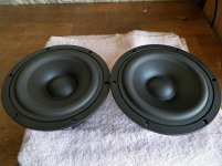
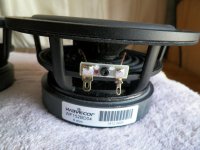
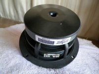
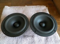
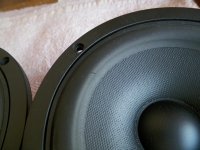
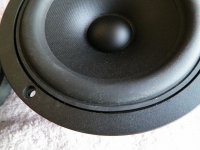
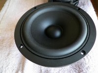
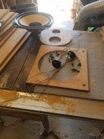
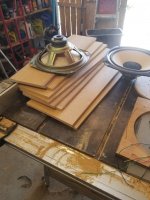
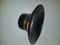
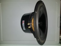
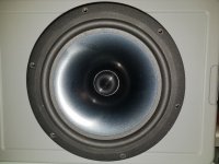
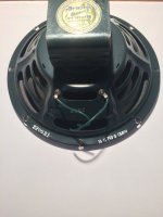
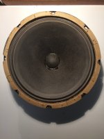
Please see the attached images.
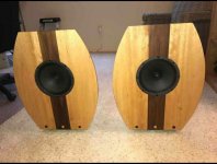
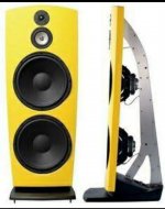
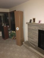
Some DIY open baffles have large (in terms of width) baffles, but some people are able to manage with smallest baffle width possible.

When i say small, i mean relative to the size of the driver.
How are they able to manage with smallest baffle size (in terms of width) ?? For example, for a 15" driver, how to manage with a baffle width of 17 to 18"

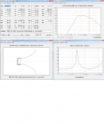
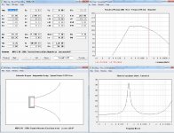
One of the important functions of the baffle is to separate the rear waves and front waves. In that sense, large baffle if preferred. But with small baffles, how is the front and rear waves separation possible ??

And then there is another concept of acoustic off center to reduce the peaks, which is obviously not possible with baffles with small width.

Attachments

  • IMG_20191209_145520.jpg
    IMG_20191209_145520.jpg
    229.4 KB · Views: 1,244
  • IMG_20191209_145536.jpg
    IMG_20191209_145536.jpg
    246.8 KB · Views: 1,655

Strange problem I havent had before.

Built up a pcb.
Tried to insert op amp and op amp legs 1 and 2 bent.
Straightened legs and tried again but op amp wouldnt go into DIL socket.
So tried putting a thin wire into pin 1 and it wouldnt go in.
Some sort of blockage on pin 1 and pin 2.
So had to desolder DIL socket and replace it.
Never had that problem before and they were RS sockets so not cheapest.

Choices for on/off switch for an amplifier: front or back panel? Rocker/toggle/pushbutton?

I'm going to begin a build for an amplifier consisting of an SMPS and some class-D modules. One thing I forgot to buy is a switch to turn the darn thing on and off. The SMPS has a universal 120/230V 50/60Hz input, so the switch should be as well. I thought of a couple of options:
1. Rocker switch on back panel with indicator light on front
2. Illuminated latching pushbutton switch on the front (must not be too difficult to depress!)
3. Good old toggle switch on rear with indicator light on front

This is just a prototype, so I am probably going to build the chassis from wood for now and the switch can't be one of those snap-in types that only work for thin metal panels. Also, cutting a square hole is a total PITA, otherwise I would consider using one of those integrated rocker switch, IEC AC receptacle, and fuse holder things. So I probably need to figure out these other AC power components too... I do have some parts around somewhere that I should be able to use for this purpose for now.

The other thing to think about is inrush and arcing of the switch. Which type is best against this, or how should I protect the switch? Am I over thinking that?

If the amp build works out I will probably move it into a 3U slimline chassis from the DIYaudio Store, and then I can incorporate better quality AC mains connections and fusing, etc. At that time I will need to make a hard decision on the type and location of the power switch. For now I need to get something working and test it all out, including the switch type and location.

Your one or two cents are appreciated. Thanks!

Scanspeak 18W8545K pair in usa

Sold.

In good condition, working and sounding great.
Bought earlier this year but not able to keep up with speaker building interests anymore. Health and age has caught up with me, and need to slow things down.
Shipping is from California 95521. Please let me know your zip code so can check cost.
I’d like to get 160 plus shipping.
Thanks, Don

Attachments

  • 54C75E5D-706C-466F-BAFD-9F0BA2BCEE71.jpeg
    54C75E5D-706C-466F-BAFD-9F0BA2BCEE71.jpeg
    949.1 KB · Views: 121
  • 32C2FB90-DC26-4656-8FFD-F048B7A2B54C.jpeg
    32C2FB90-DC26-4656-8FFD-F048B7A2B54C.jpeg
    665.9 KB · Views: 110

Modifying the Subbu V3 DAC

After discussion with Jean-Paul, the creator of the Subbu DAC V3 (along with Subbu), it was decided that it would be better to have a separate thread to discuss tweaks/modifications from the "standard" BOM build. That is the purpose of this thread. I previously commented on my experience with alternate parts for an early prototype of the V3 DAC. I'll repeat those comments in the next few posts to kick things off.
---Gary

Additional comments added March 10, 2014

After considerable discussion in this thread, there is a consensus developing on a good set of mods and parts that could be the basis for a new BOM. If you don't feel like reading the entire thread, here is a short summary.

C17 - 1uf X7R MLCC Ceramic capacitor (many possible vendors)
C22 - 470uf 6.3v Panasonic SEPC 6SEPC470
C32 - 1uf Wima MKS2 with 2.5mm lead spacing - MKS0B041000F00KSSD
C35 - you should use either C32 or C35, but not both. If you want to experiment with larger values of Wima MKS2 that only come with 5mm lead spacing then use the C35 location instead of C32. You should not use a value >4.7uf or the sound gets worse.
C4 - 1uf Wima MKS2 with 5mm lead spacing - MKS2-1/50/10 or MKS2-1/63/5T or MKS2C041001F00KSSD

Further comments September 1, 2014

The use of 1uf X7R MLCC ceramic for C17 has proven to be controversial. Some people report better sound with the original BOM recommendation of 4.7uf tantalum. Others have recommended bypassing the 1uf X7R with 100nf X7R but androa17 has done good work looking at this and recommends the following to avoid oscillation.
Best: 10uf tantalum + 100nF x7r
Next: 4.7uf tantalum (the original BOM)
3rd best: 1uf X7R

JP has used 1uf X7R for C17 in all his recent builds and reports no problem. In all of my builds I have used 0.22uf COG caps and like the sound and haven't seen any oscillation. So the 1uf recommendation stands.

Nelson's peg-board?

Hi everyone.

I saw an interview with Nelson Pass where he talks about the process of learning to develop the amplifier circuits. He has a good story about making a sort of "box" for changing around components to test new circuits while prototyping new amplifiers.

Has anyone ever seen a circuit for something like that?

It would be cool if Nelson was lurking and could expand on this a little bit.

Thanks for reading my post.

/Dan

Here's a link to that interview section:

Login to view embedded media

How do I size capacitor for off-line LED strip?

I bought a pair of LED "IS" tubes. Fixture takes just one, put it in - lights briefly then goes out. Box says I need an "Instant Start" ballast. No way am I buying that retail...

So I busted one open, looks like a full wave bridge with the 80 count LED string between + and - output, with a 22uf filter cap in parallel. Then a 0.1 uf film cap on one leg of the input, a small inductor on the other.

Looked on line and finally found a pdf where the LED current of one of these tubes was mentioned, 50 mA with 60 max. Using a 100 Ohm series resistor and a variac, I dialed up the voltage until I got 50 mA of AC current - as read by my DMM. This lit the string nicely. The voltage across the string was 93V, so 118-93/0.05 gave 500 Ohms.

Deciding I wanted to use a cap instead of a resistor (as per original), I calculated 5 uF as giving 530 Ohms at 60 Hz. So I replaced the resistor with a 5uF film cap and my current reads significantly more than 50 mA - on the DMM. Fiddling, I ended up with 3.2uF and just OK brightness for a ~50mA DMM reading.

Do I need to use the oscilloscope to look at the current waveform, to ensure I'm putting 50mA RMS through the string? I'd like as much light as I can get, without killing the reliability.

cloning an output transformer

I want to build a transformer with the same characteristics as the hammond 125a, since I cannot buy it and it is very expensive to import it, what calculations do I need to do from the values that the data sheet gives me to be able to have everything to be able to build it?
And if it can't be done, where can I get information on the design of push pull output transformers, since I couldn't find much on the internet
I leave the link of the data sheet
https://www.hammfg.com/electronics/transformers/audio/125a-125e.pdf

Crucial.com PC DRAM

Just a heads-up.

For 23 years I have bought PC DRAM from Crucial.com. Fast, fresh, fits, and priced right.

My new-to-me UltraBook could use another stick, so I ran their Compatibility Tool and ordered it.

12 days ago, and still "processing". My last order in 2018 shipped in 12 hours.

Even WalMart and HomeDepot are shipping faster than this.

Yes, I know there is a supply chain crisis. But Crucial is/was partnered with Micron, the big DRAM plant in Idaho, and selling at higher prices than they could get from their OEM customers. Also Amazon shows stock of this part, for $3 more.

I looked around. A LOT of Crucial customers are saying Crucial took their money and did not deliver, or delivered very slow, or delivered bad goods and avoided refund.
Also, a lot of spam on sites where I know a maker can have off-topic spam removed (ResellerRatings, BBB), but they are not clearing the spam. (Mostly investment advice?) Don't they watch their reputation?
https://www.sitejabber.com/reviews/crucial.com
https://smart.reviews/business/crucial.com
https://forums.hexus.net/general-di...g-direct-crucial-proceed-extreme-caution.html
https://www.resellerratings.com/store/Crucial_Technology

I note that Crucial is really now an arm of Digital River. Which used to be a mediocre shareware payment service, but seems to be something else today. It is notable that half of Crucial.com's pages are excellent, and a few are really slap-dash, like new owners redecorating in a rush. Also the Returns page is Not Found, a very bad sign. The Agreement contract is really long and very favorable to them. (A few reviewers say this was thrown in their face.)

It's 'only' $32, I paid on my Amex (who will side with me), and they have not even billed Amex yet. Maybe it is a misunderstanding or short-staffing.

But I'm in limbo-- will it come? Should I cancel and order at Amazon? ("Ships from Amazon" means they have it in a Bezos building, right?)

Anyway: if you too remember Crucial favorably, watch your step.

  • Locked
GIANT caps Mallory 17500 MFD 22000 17000 GE Sprague -- NH USA

$999 or best offer 😕😀

Attachments

  • IMG_20201209_141611.jpg
    IMG_20201209_141611.jpg
    977.8 KB · Views: 954
  • IMG_20201209_141656.jpg
    IMG_20201209_141656.jpg
    897.3 KB · Views: 957
  • IMG_20201209_141707.jpg
    IMG_20201209_141707.jpg
    795.1 KB · Views: 933
  • IMG_20201209_141721.jpg
    IMG_20201209_141721.jpg
    851.9 KB · Views: 906
  • IMG_20201209_141733.jpg
    IMG_20201209_141733.jpg
    810.7 KB · Views: 848
  • IMG_20201209_141748.jpg
    IMG_20201209_141748.jpg
    848.7 KB · Views: 391
  • IMG_20201209_141800.jpg
    IMG_20201209_141800.jpg
    922 KB · Views: 428

Horn/TL combo

I have been mulling over where to go with my next speaker project. I have come fro pro multiway world and found my way to FR speakers as a result of the forum. I love FR, but they have their limitations. I will be exploring the AN 15 OB tied to woofer as an extension of that, but have also decided to go down the horn road as well. This is mainly due to Lynn's Beyond the Ariel thrad. Having not heard a horn system, I want to something a little cheaper than what he has arrived at, so I will be having to make some choices. ANy suggestions are appreciated, but what i was thinking was either a 12" or 15" pro woofer in a TL/MLTL, TQWT....whatever else of some sort, crossed to either a 1" or 1.4" Horn driver in either a JMLC or Iwata horn. I may try a cheap SEOS platic 12" since it is only $25 each as a first dive, but ulitimately will finish with a pure horn type. If I go Iwata, i may try DIYing them. Otherwise they will come from DiySoundgroup. THe HF drivers I am looking at are the new polymer ones from Faital Pro. THey are new and interesting and have been recommended by a fellow audio enthusiast. SOrry for the ramble. Be forewarned of many more like it😀

A 'Live-in' Bass horn?

Just for laughs, I happen to have acquired 32 x Tannoy 6.1/2" drivers, and my electronics cave up in the roof happens to resemble a horn in my mind - represented by the black hanging rope! The 'mouth' is about 3m wide x 2m high and the throat about 2.5m x 0.6m high which would accommodate the drivers quite nicely in the layout shown on the floor.
As I said, just a bit of cheap fun with few expectations - people's comments please.

20180616_175401.jpg

Enclosure for Eminence Kappa 12A

Hi everyone

I'm new to this forum and hope I can get a little help or building suggestions from you. 🙂
I would like to build a midbass enclosure for my Eminence Kappa 12A. The only requirement is that te driver has to be direct-radiating to produce also some mid sound.
Is it possible to build a horn or should I use a vented enclosure? The size does not matter much, but it should be no more than 100 cm high, 50 cm wide and 40 cm deep. Something like a like a floor standing box maybe?
The mid driver on this box will be a Fostex FD600 to play the mids and highs, or maybe a seperate tweeter for that.

My goal is to use this enclosure from about 80 to at least 650 Hz. I tried a simulation with Hornresp but I'm not there yet.

Thanks for any help in advance!
Jay

Wavecor -- WF182BD04 -- WF152BD04 -- WF152BD02 -- TW030WA07 and 08 tweeters

Wavecor -- WF182BD04 -- WF152BD04 -- WF152BD02 woofers -- TW030WA07 and 08 tweeters

Need gone
make offers.
Everything is half price of retail.


(2) WF152BD02 -- $90/pair shipped -- used, look good except one has soldered terminals. SOLD
(2) WF152BD04 -- $160/pair shipped -- NEW SOLD
(2) WF152BD04 -- $130/pair shipped -- NEW -- small 2 mm cut on surround of one of them, but did not go through -- on thick part of the surround and it's a very shallow cut. Much more noticeable in the close-up pic, than with the eye.SOLD
(4) WF182BD04 -- $185/pair shipped or lower if NE US or close -- NEW Price lowered
Solen.ca: "GrandTotal 411.61$" Not sure if that is CAD or USD or both or if it includes shipping.


----------------------

Combine with WF182 and I will lower prices.

(4) TW030WA07 tweeters -- $75/pair shipped US48 -- PAIR NEW, but domes are green with some having a little black mixed in.
(2) TW030WA08 tweeters -- $75/pair shipped US48 -- Pair USED
(2) TW030WA08 tweeters -- $100/pair shipped US48 -- Pair NEW


An externally hosted image should be here but it was not working when we last tested it.


An externally hosted image should be here but it was not working when we last tested it.


An externally hosted image should be here but it was not working when we last tested it.


An externally hosted image should be here but it was not working when we last tested it.


An externally hosted image should be here but it was not working when we last tested it.


An externally hosted image should be here but it was not working when we last tested it.


An externally hosted image should be here but it was not working when we last tested it.


An externally hosted image should be here but it was not working when we last tested it.

Attachments

  • 101_1622.jpg
    101_1622.jpg
    993.4 KB · Views: 163
  • 101_1625.jpg
    101_1625.jpg
    853.6 KB · Views: 162
  • 101_1628.jpg
    101_1628.jpg
    798.6 KB · Views: 160
  • 101_1629.jpg
    101_1629.jpg
    997.6 KB · Views: 145
  • 101_1630.jpg
    101_1630.jpg
    814.7 KB · Views: 155
  • 101_1635.jpg
    101_1635.jpg
    832 KB · Views: 154
  • 101_1613.jpg
    101_1613.jpg
    1,004.3 KB · Views: 140
  • 101_1614.jpg
    101_1614.jpg
    914.3 KB · Views: 150
  • 101_1615.jpg
    101_1615.jpg
    963.6 KB · Views: 155
  • 101_1616.jpg
    101_1616.jpg
    970.1 KB · Views: 139

Need help for designing preamp with LM4562

Hello all,
I am working on a simple pre amp design with LM4562 and I will appreciate your thoughts and advises on that.
Here are the questions:

1) There is a 47 ohm resistor R16 right at the end of the output stage to isolate it from the cable capacitance.
There is another 47 ohm resistor R15 to limit in-rush current into coupling capacitor C5 which also prevents parasitic capacitance from cabling.
Is there a problem with this figure or in another word should I omit one of them or they are working just fine?

2) The voltage gain I needed for this stage was 2 so I chose 1k ohm for feedback resistors R11 & R14 and the reason for choosing 1k was for noise considerations.
Since the output current of LM4562 is around +/-26mA, I thought there wouldn't be a current issue when generally there is no need for output voltage more than 2 volts to drive any amplifier.
Is it safe to stay with 1k resistors?


Untitled.png

Marantz PM32

Just a few notes on one of these i picked up cheap as dead.

The 1Amp fuse on the a/c transformer board was blown and I checked the DC power supply to find only 1.6Ω across the bridge rectifier! That might have some bearing on it!

I thought it might be one of the 2 transisorts on the output of the power supply, which seem to serve as stabilisers- but no!

It was 2 of the output transistors (darlington) that were shorted collector to base (1.3Ω) I removed the offending and at least had an amp with one channel working.

Ordered 2 new ones 2SB1254 + 2SD1894- and its all up and running. it does have the annoying selector switch issue which is probably caused by age/misuse oxidisation- but i doubt Ill be bothered to desolder it as its a fairly fragile looking device and threads on here are mixed about swapping them out for a 'traditional' type.

The reason the Darlingtons were shorted was probably the cracked solder joints on the sc2240 transistor -

APEX A40 - PCB

Hello guys!

A fresh new APEX A40 PCB layout is here, the RED Devil Edition! In this thread group-buys for the printed circuit boards are arranged.

It's a bipolar BJT based Class-AB amplifier with symmetrical "current feedback" input stage topology and triple emitter follower (TEF) output stage, and it is state of the art of the APEX AB-Class Audio Reference Power Amplifier. Power rating is 100W/8R0 and sound is very pleasant.

APEX A40 - Layout (1).png


APEX A40 -Preview.png


2-min.jpg


Group Buy Information:

The PCBs are 122mmx105mm 2-Layer, 1.6mm FR4, 70micron copper, HASL finish, white silkscreen and red solder mask, as shown in the above pictures.

> The PCBs cost US$10 a piece. (One PCB is for one channel, so for stereo amplifier you need 2PCBs)

> After the GB list is full, each user will be contacted and sent the first invoice for PCB cost, and the rest (including shipping charge, packing and processing charge and PayPal charge) is to be paid before shipping the boards, for which the second invoice will be sent.
International payments are accepted ONLY through PayPal.
Delay between placing the batch order to PCB plant and delivery of the boards to me will be 20-30 days.

Shipping Information:

All PCB will be send to buyer address using Registered Post with tracking number. Delivery date is around 10-30 days depends on country.

List Information:
Please write your diyaudio forum nickname (country) - number of boards.

Group Buy list is open for everyone that wants to get these nice Red Edition Boards for Audio Reference Amplifier APEX A40.

Group Buy - APEX A40 List

ronovar (CROATIA) - 2pcs

Beryllium expanded usage?

Why is there not at least a 6” BE midrange? Is it too brittle? What about beryllium formers? Apparently it had amazing temperature related properties? Is it magnetically inert enough? The BE former could theoretically be literally part of the BE dome or cone (shape and contours and thickness is also important but there’s a company in LA called LA Guage that has extremely impressive abilities to mill it and a thin dome with any thickness and an extremely thin former could probably also be worked out but those are so thin i’m not sure if humans can machine .001mm or whatever it is either way as a number of stiffened foils which must be possible, this could change things what’s going on? I know how lethal it can be but this clip shows some great promise

Login to view embedded media

diytube ST35 clone (Shannon Parks Rev B) for parts or repair. $300

I built this amp in 2002 and it has served me well, but when I removed and replaced some bulging caps recently I damaged the board. It still ohms out but it doesn't light up. I'd like $300 for the whole thing, including some older but still working JJ tubes, and some very nice KLE RCA inputs. The Hammond transformers (272FX Power and 1650F outputs) sell for $375 now on Mouser, so this seems reasonable. But I'm open to offers or to parting it out.

I also have a brand new Alps Blue Velvet 100k pot, diyaudio connection board and knob that I will sell for $20, and a matched quad of JJ El84s, balanced 12AU7 and 12AX7 purchased new from Eurotubes in late February that I will sell for $100 (currently $125 on eurotubes.com, more from other vendors.) Less than 10 hours, so not even broken in.

Attachments

  • IMG_0308.jpeg
    IMG_0308.jpeg
    335.1 KB · Views: 188

Cheap materials for goofing around with speakers.

What 10 bucks gets you at the thrift store.
Three circle templates.
A stack of half inch MDF, great for testing small enclosure designs.
(To me this is the real value as ply is so expensive, hard to move from store, and is unsuitable for goofing off from a cost perspective.)
Four 3.3Ohm 5w.
Two 6.8uF.
Two 5uF.
Twenty four black screws.
Two 10 inch cone woofers. (Good for learning the relationship between T/S and enclosure with real world example.)


Jeremy

Attachments

  • 20220713_152108.jpg
    20220713_152108.jpg
    454.8 KB · Views: 105
  • 20220713_152112.jpg
    20220713_152112.jpg
    510.7 KB · Views: 106

Speaker Drivers (Some Free)

10 Qty - Peerless 8" W8-12T 12PS (Free)

4 Qty - Dayton Audio 10" RS2700S-8 ($5 each)

Buyer pays shipping and paypal.

Local pickup ok.

Vince
Wayne PA, USA

Attachments

  • 20220706_203112_resized.jpg
    20220706_203112_resized.jpg
    174.7 KB · Views: 144
  • 20220706_203138_resized.jpg
    20220706_203138_resized.jpg
    100.9 KB · Views: 141
  • 20220706_203201_resized.jpg
    20220706_203201_resized.jpg
    122.3 KB · Views: 139
  • 20220706_203213_resized.jpg
    20220706_203213_resized.jpg
    206 KB · Views: 138

DML acrylic panels

Saw an interesting video amplifydiy. They compared bamboo and acrylic. The bamboo sounded "richer" smother than acrylic. The acrylic had better top end and more detail. It's going to take alot of trial and error to get these things to become popular or accepted. Some their inexpensive build cost will drive the enthusiasm. For now seems midbsss and midrange is where there at now. Another point he made was the importance of attachment design and quantity and placement of them. Only way to move onis to keep thinking out side of the box. Keep on experimenting, I am have fun with the excitor. Pun intended. Michael
  • Like
Reactions: Makro1

For Sale F5 partial SMD boards, unique power supply board, and most parts

SOLD

ASKING $225 including Continental USA shipping


This is another project I will not build, seeing if another might have an interest in it.

Designed by Jason Leaman and others, this is a super heavy duty implementation of the F5 with a stout CRC or CLC power supply board.

Login to view embedded media
He used some atypical parts, mainly the SOT 227 footprint power mosfets and diode bridges. The boards are NOT UMS mount compatible so you must be provicient at drill and tap of heatsinks.

The signal boards call for mostly MELF resistors, but use standard 3W power resistors. ixys IXTN40P50P and IXFN140N30P huge mosfets are used and mount the boards to the heatsink. Screw connectors can board mount for wire attachment.

dimensions: 260 x 52 x 1.6mm

I include all parts needed for the signal boards except the input jfet J74/k170 pairs, the spade connectors for signal input and signal ground, if you want to use them, and SMD LEDs. The mosfets retail for about $75 per board.

There is a schematic and BOM included, support from Jason has been hard to come by, so I suggest you are an advanced builder, familiar with First Watt amps and power supplies if you take on this project.

The PS board is HUGE (244 x 189 x 1.6mm, NOT UMS mount compatible) and can be set up for CRC or CLC filtering. I will include the Microchip APT40DR160HJ Diode bridges that fit the boards, 16/ea Nichicon 15,000uf 35v capacitors, screw mount connectors, and fuse holders. No resistors, film caps or chokes included. There is no schematic or BOM for the power board. Pretty self explanatory, and he runs over it nicely in the linked video.

So, for less than the cost of the 6 SOT227 parts and the 16 PS capacitors you have a partial kit for an F5 type DIY amp. You supply the other board parts, chassis and chassis components.


IMG_0732.JPGIMG_0733.JPGIMG_0734.JPGIMG_0739.JPGIMG_0740.JPGIMG_0741.JPGIMG_0743.JPGIMG_0744.JPG

my Schurter switches keep breaking

Hey folks, dropping a line to encourage other hobbyists to avoid the Schurter push-push switches. They look great and work wonderfully for a while, but one of mine spontaneously stopped working yesterday and will not latch with the supplied push button.

I have this part in two of my builds:
1241.6821.1120000

https://www.mouser.com/ProductDetail/693-1241.6821.1120

Conversely, if you are into cycling your amps for stress tests or you prefer to hold your finger on the "on" button during the duration of a record, Schurter may be a good choice for you.

For Sale Hammond 274BX power transformer

Greetings,

I have a brand new Hammond 274BX power transformer (box never opened). When ordering the various parts for a tubelab SSE build, I accidentally ordered 2 power transformers. Ships from Canada (SK)


Power Rating (VA) 198
Primary VAC 115 / 125
Primary Frequency 60
A.C. High Voltage Secondary RMS 750V C.T. @ 201ma.
Filament # 1 VAC 5V C.T. @ 3A
Filament # 2 VAC 6.3V C.T. @ 6A
Mounting Type Vertical ("X")

Full specs here:
https://www.hammfg.com/files/parts/pdf/274BX.pdf
asking price: CAD: $120 + shipping (~ CAD $20 to ship within Canada) - CAD $45 to ship to USA.

audio test: 100hz and 1000hz sines with different delays

Hi, diyaudio!

Attached is a flac that plays a 100hz and 1000hz sine 3 times. They all stop at the same time but the 1000hz starts with a delay of 0ms, 1ms, and 2ms.

The levels of 100hz and 1000hz are the same so it can be hard to hear 100hz over 1000hz. Putting the ear near the woofer can help with hearing. Play the clip a few times and try to lock onto the bass tone.

The question is: do the samples sound similar or different?

I am trying to exploit a slower group delay on some of my speakers and this is my first go at a test.

Thanks!!!!

Attachments

Vulcan a good choice for my room?

Hi - I have been so impressed with the knowledge shared in the diyAudio forums, thanks to everyone for their contributions!

Like many other newbies, I am trying to sort out my first full range system, and wanted see if I am on the right track (primarily regarding my choice of enclosure). My goal for the system is to get a good flavor for what a high efficiency, simple single driver system is like. This is what I am planning:

Driver: FE206En (purchased)
Amp: F2J Clone (parts purchased)
Preamp: Salas DCB1 (parts purchased)
Source: Old Sony CD Changer, Old Technics Turntable
Enclosure Options:
1) Woden Designs Vulcan (preferred if it works in my room)
2) Kirishima
3) Dallas II

The room is 31' x 14' (9.4m x 4.3m) with a 7'-6" ceiling height (2.3m). The speakers would be placed against one of the long walls and the listening chair is positioned against the other long wall.

Will a fire place between the speakers that extends 6" out of the wall at the top and 15" at the bottom cause a problem with the boundary loading of the rear horns on the Vulcan? The picture below shows a full size cardboard mock-up of the Vulcan next to the fire place.

Thanks so much!

Attachments

  • IMG_1360.jpg
    IMG_1360.jpg
    61 KB · Views: 564

For Sale Singing Bush Power Supply boards from R. Thatcher

SOLD

Asking $20 including CONUS shipping

For sale are a set of Singing Bush Power Supply Boards, Rectifier/snubber boards and CL-60 AC cap boards. I am not going to build an amp that needs these.

I also have a pair of KBPC3506 rectifier bridges that fit the boards I will throw in if you want them, let me know.

Shipping to Continental USA included in sale price.


IMG_0622.JPGIMG_0623.JPGIMG_0624.JPGIMG_0625.JPG
  • Like
Reactions: bOTL

Steve Bench A2 amplifier: what's that coupling stage?

Can anyone explain how the coupling with the voltage reference tube // 5.6nF cap works? The designer states that it is a fully DC coupled amp, but I can't get my head around how the signal passes in that middle stage if it weren't through the cap. His explication leaves me equally perplexed:

"Incidentally, notice that the voltage at the grid of the cathode follower driving the 841 is near zero volts. One could then ask why the complication of adding the DC coupling, and the reference tube. Well, indeed I tried that, and the amp measured OK, but sounded VASTLY inferior to the DC coupled circuit. Distortion cancellation anyone?"

http://diyaudioprojects.com/mirror/members.aol.com/sbench/a2part2.html
Thanks for shedding a light,
Simon

LM1875 PCB design

Hi, Im making lm1875 amp with ne5532 op amp only for balanced input and voltage regulator for the op amp and i have no idea how to ground it on one 2-layer pcb. Does i need use star grounding or just ground plane? All components are THT so i thought i put only ground plane on bottom and all other places on top. What do you think, can you help me please?

RJM with 12AY7

Has anyone ever tried to do the RJM passive phono with 12AY7 instead of the 6922? Mu is similar so it seems doable?

I have heard that the RCA circuit is not appropriate for AY7 due to lower mu (compared to AX7) but the topology is quite similar to RJM which uses a 40ish mu tube. As far as gain goes both RCA and RJM are two stage passive. So I would also be interested in hearing from anyone who has done the RCA phono with AY7s also.

Aleph J PSU thermistor

Hi Guys
In the aleph J PSU, which is the function of the TH1 thermistor circled in red?

PSU.JPG


he is critical to safety?
In my Aleph J the metallic 4U chassis it's completely isolated except from the IEC earth. The GND PSU, all speaker terminals and RCA connectors are completely isolated from chassis and TH1 is not mounted.
It's correct or not safe for electric shocks?
Thanks

Midrange horn design, cone-driven - 201

I’m in the process of building my first horn and would very much appreciate input from experienced users. Many have helped me learn about horns from scratch in my midrange horn 101 thread – thank you very much!! It has been an intense learning experience.

The system is 4-ways fully active, DSP with linear-phase crossovers, time alignment. The tweeter is a Beyma TPL-150H, and the horn to be designed is targeted to operate from 400 to 2500Hz. Below the midrange horn, a pair of direct radiators per side in sealed boxes, and below that subwoofers in sealed boxes. One goal is to use this horn directly connected to a 45 SET. Another 45 SET for the tweeter. Below that is class-D.

Given what I learnt at my other thread I purchased Faital Pro M5N12-80 for these horns. I was advised to use a flare cutoff frequency about an octave below the intended xo point to minimize colorations from the horn at the lower end. I’m taking 215Hz for fc.

One significant decision is shape of the mouth: circular vs. rectangular. Circular has the benefit of a more even and predictable response, while rectangular (2:1 width:height) has the benefit of reducing the center-to-center distance between the TPL and midrange horn (which is still going to be larger than twice the 2500Hz wavelength). Feedback on this will be helpful.

A Hornresp simulation is attached below. It’s a tractrix profile extended to 90°, with a circular mouth. S1=Sd, and fc=215Hz. Mouth comes out to be S2=1990cm2. Both attachments are the same, but one is lower resolution. I can't figure out how to unattach a file here...

As of today I’m leaning towards a rectangular horn. Open to be proven wrong, though. Bruce Edgar’s Tractrix midrange horn is a bit of a baseline for me.

I’m thinking either tractrix or LeCléac’h with 0.7 factor and limited to 180° opening for the width profile. For the top and bottom sides I’m not sure if I should settle for the simpler to build conical (like Edgar’s), uniform or exponential profile. What do you think?
Keeping the 2:1 mouth aspect ratio, a 631 x 315mm mouth will have the same surface as S2 above (1990cm2).

I guess before I go further into the design I should decide:
  • Rectangular vs circular mouth
  • If circular: Tractrix vs. LeCléac’h
  • If rectangular: profile for the width and profile for the height.
Any additional feedback very welcomed!

Attachments

  • midrange drivers.png
    midrange drivers.png
    98.1 KB · Views: 2,829
  • midranges.jpg
    midranges.jpg
    207.1 KB · Views: 2,884
  • Like
Reactions: DblAA

Selling prototypes on ePay (Edelweiss-3 vacuum tube amps)

Hi!

I have some prototypes on ebay, "make your offer" listings. I am interested in feedback from real audiophiles who enjoy fine sound quality. Since 2019 when I started the project, I sold a dozen, with modifications that improve their features step by step. The design is close to the end production, but not finished yet, so you have chance to get the working prototypes and participate such a way in R/D process, helping me to self-finance it.

https://www.ebay.com/itm/185295464131

https://www.ebay.com/itm/185288710253
  • Like
Reactions: JMFahey

H&K Tubeman Circuit Questions (added schematics!)

Hey guys!

I've been around this forum for a week or too now, having got interested in a diy - guitar amplifier project!

I have not much experience with electric circuit design, so I'd like to ask you seasoned pros for some guidance on the following problem:

I've acquired this '92 Hughes & Kettner Tubeman recently, an amazing recording tube preamp. Unfortunately I used a 19V AC power supply instead of the suggested 12V AC.... It worked for a few hours very decently, but now it's dead. I'm an idiot I know, but now I want to fix it very desperately.

So I got out my trusty old multimeter and checked some diodes and stuff, and I noticed that two diodes (D1 and D2) were not working properly anymore, they were conductant in both directions.

Now my questions are

a) What could these diodes, in connection with the rectifier B1 just below, be for? I can't make any sensse of this.

b) Could it be that using a 19V supply fried them (and/or any of the ICs? I hope not! :-( )

Thanks in advance!!

Attachment:
404 Not Found

Got these caps, how can I test them?

I recently discovered my local electronics store has a whole pallet of these 33,000uf 63V caps and the owner sent me home with 4 free ones to try out. He informed me they have had them for 15+ years, so of course I am skeptical about them working.

What’s the best/easiest way to ensure these are properly charged and tested before trying to use 4 in a Pass Amp?

I purchased a variable power supply that can go up to 60V 5A. I was told I could slowly charge them by adding a 3K ohm 3 watt resistor in series. I was able to get a 3.4k ohm 10 watt resistor to use.

A few questions:

- how slow should I charge them with the DC supply? Or what process should I follow?

- is this method a way to test and ensure the caps work?

Any help or feedback is appreciated.

Attachments

  • FF1A45FB-07C2-4A64-B03F-477CCD905A6B.jpeg
    FF1A45FB-07C2-4A64-B03F-477CCD905A6B.jpeg
    272.8 KB · Views: 130

wiring parallel or series sensitivity rules?

Hello

I need to clarify these rules, I know how to wire in series and parallel like anyone would but I don't know how this affects sensitivity's


Now for my example, assuming you had an amp that put out 100 watts at 4, 8 and 16 ohms, and a woofer that had an spl or whatever it called at 100 db 8 ohms at 1 metre with 1 watt

Now say we wire one speaker to the amp, its sensitivity will remain 100db/8 ohms/1 meter

Now say we wire 2 of the speakers in parallel making a 4 ohm load, I assume the sensitivity now rises to 103 db because a doubling of cone area at the same watts

Now say we wire 2 in series causing a 16 ohm load, I assume again that the spl now rises to 103 again because of the doubling of cone area,

Based on that does parallel and series sensitivity go by what the amp can out put at certain ohm loads

Or give me a realistic exmaple

Thanks 🙂
  • Like
Reactions: DblAA

Scanspeak Beryllium vs Mundorf AMT vs Usher 9950-20: your subjective opinions wanted

Like the title says, I want to hear anything you have to say about these tweeters compared to one another, especially from people who have heard all three. Let's just assume that all three are ideally implemented in a speaker design. Some points I'm interested in:

1. Sound
2. Value-for-money
3. Your personal choice and why

Any insights are welcome though 🙂

FS: Werner Jagusch Altec A7 crossovers

Selling 1 pair of Werner Jagusch Altec A7 crossovers

For Altec A5/A7 with optional tweeter.

In excellent condition, both electronically as cosmetically

They should work in a number of different configurations of a 416/515 woofer, used with a 288, 801, 802, 806, 807, 808 as horn driver with numerous horns such as 511, 811, 1005, 1505,...
The horn circuit uses an autoformer to adjust the sensitivity of the horn to the woofer

Asking 400€/pair

Attachments

  • IMG_2325.jpg
    IMG_2325.jpg
    642.8 KB · Views: 884

NAD C352 little to no sound on one channel

Hi.
I'm not super knowledgeable about amps but i know some electronics. So thought I might give it a try.

Setup:
Nad c352
Two Jamo CBR 1302 speakers

Description of problem:
When the amp has been on for a couple minutes, less than 20 min, the right channel goes loser and lower till it is totally quiet.
If i turn it off and on again it still has the problem. But if it's off for some time( a day or so) it starts normal again then goes quiet. So I'm thinking it's some temperature problem...
Anyone here have an idea of where to start?

My regards
-Noah

Ebay NE5532 pre amp tone control gain reduction

These are on eBay as YX1099 and WM-025 with the latter looking as a better design. After building the first one I found the gain so high it was overloading the input on a little Tripath amp. When used as additive equalisation, the amp would distort so subtractive equalisation was only possible.

The gain is set at 10 by the 100K resistor near the first op amp (inverting) in conjunction with the 10K input resistor. To solve my problem changing the 100K to 10K gives a gain of 1 which matches my source and amp with the volume the same as previous. As I didn't want to remove the 100K, I paralleled a 10K to give around 9K which gives gain of 0.9. I've mentioned this as there is a zillion of these things being sold and others may have the same issue.

I only used the PCB from the kit and used my own components as they are of known quality and ended up using LM4562. One thing I did add was a 100nF monolithic by-pass cap between pins 4 and 8 on each op amp under the PCB. I also run this via a 12VAC wall wart instead of a 12-0-12AC supply with a centre tap.

Hope this helps someone in the future and even though I used 10K, if more gain is required then use a higher value.

Attachments

  • Tone_YX1099_mod_10K.jpg
    Tone_YX1099_mod_10K.jpg
    69.2 KB · Views: 733
  • Tone_YX1099_mod_10K_completed.jpg
    Tone_YX1099_mod_10K_completed.jpg
    160 KB · Views: 705

FS: Genuine PGA29310PA,LM317KC, LM337KC, BUF634T, LM3875TF, LM3886TF, LM1971N

It's time to declutter my life. Too many hobbies done half-heartedly.

I have a number of original ICs unused sitting in drawers doing nothing.

They would be better off in someones project(s).

Semi Qty £/each Notes
PGA2310PA 4 10.00
LM317KC 6 3.00/6
LM337KC 6 3.00/6
BUF634T 4 5.00
LM3875TF 5 3.00 Plastic Insulated
LM3886TF 5 3.00 Plastic Insulated
LM1971N 5 4.00 Discontinued/NOS


Prices are individual (except for LM317KC/LM337KC) and do not include postage.

bias circuit option

i have a spare 58Vac {unloaded} primary winding which im planning to use for both negative bias voltage for grid bias and also positive heater lift for a srpp driver stage. i came across this cct which can do what i want but needs some tweeking. can i reverse the voltages polarity in such a way that the top fullwave rectifier does the -ve bias and the bottom halfwave rectifier doing the +ve bias? thanks for any help.


1657423929248.png

How to best achieve "stereo" audio when physical separation between channels isn't possible

My project for the summer is to build a better "lifestyle" speaker. The criteria being it is a single bluetooth enabled speaker meant to be plugged into a power outlet.

My desired outcome is a fun speaker with a big soundstage so overall accuracy is low on my list. Designs that I have built and enjoyed in the past are the Cornu horn and Karlsonator.

Inspiration for this project is the Bose 901 but instead of 2 individual speakers I wanted to include two channels in a single enclosure. The thought being that using room boundary effects will increase the soundstage and provide more of a stereo effect from a single enclosure. To take things a step further I am wondering if I can use corner loading to exaggerate this effect further.

This is more of a discussion starter topic. Looking for feedback, ideas, or recommendations no matter how crazy or out there they might be. Just to reiterate, the intent is a FUN speaker not an accurate one.
  • Like
Reactions: Deric_Maverick96

Analogue delay achieved using opamps, but how?

Hi,

TI has appnote for building an active 2 way here https://www.ti.com/lit/ug/tidu035/tidu035.pdf
For time alignment it proposes a delay all-pass filter circuit to delay the tweeter, the delay is a fixed at 155us till 3.8Khz upper cutoff. Please see section 2.4 and 4.2.3.
Can anyone please explain whether this delay is really fixed at 155us from 20Hz to 3.8Khz?
I thought an all-pass filter give a constant delay in terms of phase angles and we know that a constant phase angle (in a band of frequencies) gives varying time delay, not fixed. But the proposed circuit is claimed to have a fixed time delay, how?

Thanks and Regards,
wondeflaudio

For Sale 3 x SKA amp Greg Ball - class AB - MOSFET - 150w

Hi,

Selling 3 amplifiers SKA GB150 from Greg Ball.
Preferably in EU or Worldwide
Transfo can be removed if you need other voltage and lower shipping cost.
Price 250€ / each without shipping
Special price for the 3 !

Mosfet
Max output 150w
1Vrms input
Class AB
Can make 50W into class A with some modifications

2 amps in HIFI2000 cases
300VA transfo - 230V
DC protection installed
Softstart
Few little scratches

1 amp in custom case
all metal apart wood face
Bigger transfo and caps bank - 230V
Softstart
DC protection kit has to be installed and soldered if you want
Some scratches
The bottom of heatsinks are rough hand cut

I have the manual for easy tuning.

Attachments

  • IMG_20220701_114158.jpg
    IMG_20220701_114158.jpg
    401.7 KB · Views: 171
  • IMG_20220701_114702.jpg
    IMG_20220701_114702.jpg
    255.9 KB · Views: 151
  • IMG_20220701_114757.jpg
    IMG_20220701_114757.jpg
    249.4 KB · Views: 144
  • IMG_20220701_114816.jpg
    IMG_20220701_114816.jpg
    315 KB · Views: 152
  • IMG_20220701_115518.jpg
    IMG_20220701_115518.jpg
    314.5 KB · Views: 152
  • IMG_20220701_115638.jpg
    IMG_20220701_115638.jpg
    283.2 KB · Views: 178
  • IMG_20220701_115903.jpg
    IMG_20220701_115903.jpg
    449.4 KB · Views: 170
  • IMG_20220701_120141.jpg
    IMG_20220701_120141.jpg
    331.3 KB · Views: 157
  • IMG_20220701_120208.jpg
    IMG_20220701_120208.jpg
    288.4 KB · Views: 140
  • IMG_20220701_120229.jpg
    IMG_20220701_120229.jpg
    468.8 KB · Views: 158

Astronic Equaliser type a1671

I have an "Astronic Audio Response Equaliser type A1671", 60's model I think, could someone help me with connecting this up for electric guitar recording please.

It has 9 bands & on the rear panel there are two connecting sockets one has 18 pins & the other has 4. I dont' have the connecting plugs but can work around that.

Not sure how to connect this properly?
It has an on/off switch as well as a in/out switch & a Level Pot, there is also a red light so it seems to require power?

I have attached a very poor picture of the same model I found on the Internet.

Cheers

Attachments

  • Astronic.gif
    Astronic.gif
    118.7 KB · Views: 285
Projects by fanatics, for fanatics
Get answers and advice for everyone wanting to learn the art of audio.
Join the Community
507,689
Members
7,884,367
Messages

Filter

Forum Statistics

Threads
406,048
Messages
7,884,367
Members
507,689
Latest member
Giannikos