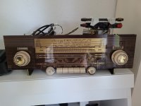
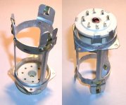
How to get inside Leak 2030 cabinet
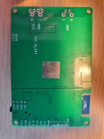
How do you get inside the cabinet of these speakers to service the electronics?


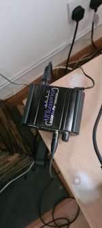


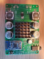
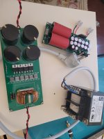
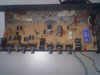
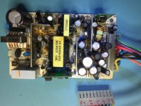
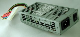
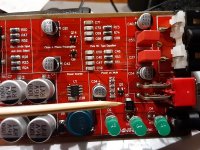
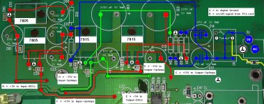
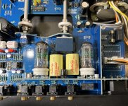
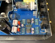
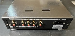
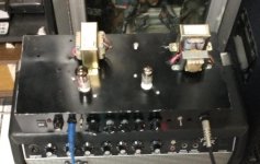
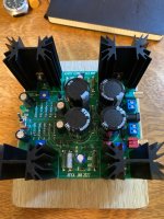
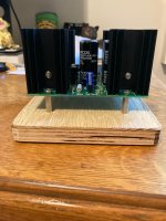
Well, I replaced 2 caps and about 4 resistors in the "Soft ON/OFF" path, and removed as much of the gump as possible and it didn't do the trick. I know that if it was a faulty cap in the output stage. it would not turn on at all."The power supply is easy to remove from the command station., is attached to the bottom with 3 bolts. I removed it and sent it to the technician. He has never seen a Command Station or similar, .....
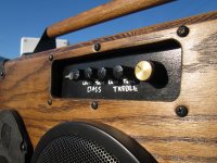
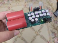
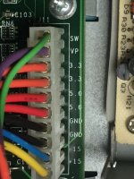
After checking it, he asked me if the "device" had a soft or standby switch , apart from the ON/OFF at the back panel. He said a resistor or a capacitor in charge to receive or process the signal from the Soft ON/OFF button was faulty.
He replaced it, and the sudden shutdown problem was resolved. And also the loud white noise never came back...."