What did you create today?

A thread for things we create, large and small, complex or trivial, to meet life's demands or for convenience. Physical things - which may not necessarily have to do with Audio A-OK.

Example; I have a bunch of camera tripods around and found it annoying that the 1/4-20 threaded based attachment mechanism is completely incompatible with any microphone clips I have. So I made an adapter, now I can use the camera tripod to hold my measurement microphone.

And the measurement microphone diameter is incompatible with any of the mic clips I happen to have...

Attachments

  • Mic Adapter.jpg
    Mic Adapter.jpg
    888.5 KB · Views: 398

2SK1058 / 2SJ162 mosfet reverse polarity???

I purchased 2 pairs of 2SK1058 / 2SJ162 mosfets in order to repair a Hafler P3000 power amp. This amp has 2 identical boards, one for each channel. I've checked this amp before and everything was in order except the 2 pair of MOSFETs, so it was basically a "drop in and go" operation. When I dropped the new MOSFETs in the fuse burned out immediately after connecting the AC cord. I took out the new MOSFETS again and also a pair of the working channel and checked with my DMM. Turns out the new MOSFETs have polarity inverted on pin 2 and 3. This is not normal, I suppose...........

New member from CA

Just joined after a long time of reading threads on here. Always been a tinkerer, though my desire far outweighs my technical knowledge. I know enough to not shock myself or potentially blow something up, but have yet to actually build anything. I do know how to solder, can build many things well, just never really ventured into electronics.

I do love my Class A stuff and am looking into a JLH 1969 amp as my first project, likely in the form of a kit, then build a power supply for it.

Anyway, I will be reading and searching quite a bit, more than posting.

-Alexander

3D Printed Speaker Driver VS Mark Audio Pluvia 7 / Alpair 7.2

Hello everyone

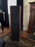
Has been a long time since I have posted here, but been super busy away from here working and improving on what I can do from a driver design perspective. Today I want to share with you all Tenacious 7 as it is getting closer to completion.
FaDNR1DWQAAA_ND.jpg

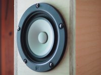
Tenacious 7 is a 50.2cm2 full range driver, placing it at the same size as the Mark Audio Alpair/Pluvia 7 series, along with stuff like the Visaton FR 10. I still have work to do, especially on the high frequency response, but lets start with the T&S Data:
Tenacious TS.png

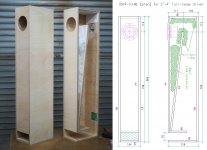
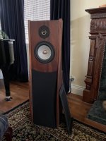
This is specifically Tenacious 7 PW and running my strongest motor design that it supports. Tenacious 7 CF is slightly heavier and so is likely low 85/ high 84dB region. Testing was done in my own TL design which was originally for the Mark Audio Alpair 7.2 some 10 years ago. This was used simply because I still use them and it isn't far of the suited design for these or the Pluvia 7.

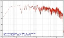
Next is a look at the upper frequency response of Tenacious 7 CF against Pluvia 7 Gen 1. Results where indoors gated to 3ms @ 1M distance, but I am in a overcrowded housing situation so some noise is possibly present:

High Frequency Response.jpg

White is Tenacious 7 CF
Red/Pink is Mark Audio Pluvia 7 Gen 1

You can see mine is a big rough and the top end rolls off to quickly. I have some ideas on fixing this, so this is where most of the final work will be focused on.

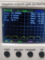
Finally is some data done at various volume levels but not calibrated, so is simply -20dB and -10dB. I can confirm that -10dB was pushing the excursion limits to around the 4mm Xmax of the Mark Audio drivers. My own Tenacious 7 CF is +/- 2.7mm to 82% BL, and +/- 3.5mm to 70% BL, so not quite as far. These measurements where taken nearfield.

Tenacious 7 20dB.jpg

^^^ Tenacious 7 CF @ -20dB

Pluvia 7 20dB.jpg

^^^ Mark Audio Pluvia 7 Gen 1 @ -20dB

T7 -10.jpg

^^^ Tenacious 7 CF @ -10dB

Pluvia -10.jpg

^^^ Mark Audio Pluvia 7 Gen 1

I could be wrong, but I can't seem to find any other 3D printed speaker drivers which are this close at competing with off the shelf drivers?

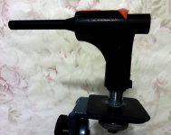
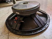
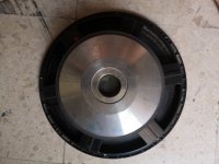
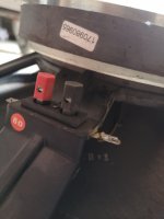
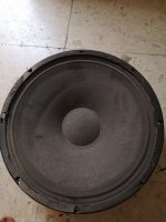
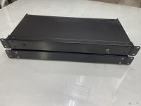
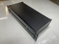
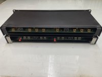
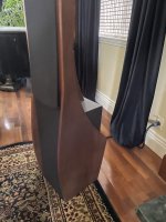
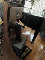
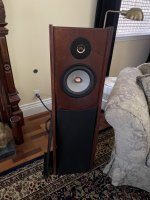
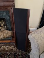
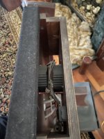
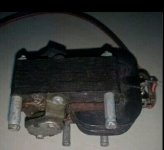
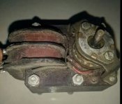
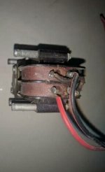
For clarity, the speaker cone, surround, spider, chassis and front fascia are all 3D printed components and designed by myself. The magnet motor is also my own design, not borrowing from any other design. In fact, the motor is removeable and can be reused for other designs and driver sizes.

Any questions / critiques etc, please fire away. I have been working on this 6 years now and I am doing what I can to improve my work

Thanks for checking out this long post!

Paul - Polymate3D

FS-USA Linkwitz Orion+Thor ASP

SOLD: Fully operational Linkwitz analog signal processors for Orion mains and Thor subs. Includes power supply and interconnect cables. $200 + shipping to CONUS.

Attachments

  • untitled shoot-12282-20220719.jpg
    untitled shoot-12282-20220719.jpg
    248.2 KB · Views: 159
  • untitled shoot-12283-20220719.jpg
    untitled shoot-12283-20220719.jpg
    268.5 KB · Views: 165
  • untitled shoot-12284-20220719.jpg
    untitled shoot-12284-20220719.jpg
    284.3 KB · Views: 175
  • untitled shoot-12196-20211117.jpg
    untitled shoot-12196-20211117.jpg
    485.1 KB · Views: 165
  • untitled shoot-12197-20211117.jpg
    untitled shoot-12197-20211117.jpg
    484.9 KB · Views: 164
  • untitled shoot-12198-20211117.jpg
    untitled shoot-12198-20211117.jpg
    385 KB · Views: 151
  • untitled shoot-12199-20211117.jpg
    untitled shoot-12199-20211117.jpg
    495.2 KB · Views: 158
  • untitled shoot-12200-20211117.jpg
    untitled shoot-12200-20211117.jpg
    542.1 KB · Views: 153
  • untitled shoot-12201-20211117.jpg
    untitled shoot-12201-20211117.jpg
    503.3 KB · Views: 156
  • untitled shoot-12202-20211117.jpg
    untitled shoot-12202-20211117.jpg
    483.4 KB · Views: 152
  • untitled shoot-12203-20211117.jpg
    untitled shoot-12203-20211117.jpg
    478.7 KB · Views: 151
  • Like
Reactions: d to the g

Arrg, CDC does not know the difference between dB and dB(A)

This article appeared in the NYT yesterday:
https://www.nytimes.com/2022/08/16/well/live/headphones-hearing-loss.html#commentsContainer

It irked me that the author and the docs she interviewed talk about decibels. Turns out the CDC article linked in the NYT article doesn't get it right, either. The NIOSH article linked by CDC does.

https://www.cdc.gov/nceh/hearing_loss/what_noises_cause_hearing_loss.html

It also contains gibberish: The time estimates listed in the “Typical Response” column are based on the NIOSH exchange rate of 3 dB. Huh?


The 80 for 90 rule that the first doc in the NYT article refers to is also cute in that it implicitly assumes that volume sliders, output voltage and headphone sensitivity are standardized. And we haven't even talked about output and headphone impedance.

Confirms my prejudice that most MDs know just enough about science and tech to be dangerous.

Rod Elliott saves the day again!

Well, I must commend Rod Elliott for his wonderful site and projects!

His P38 "auto relay" circuit works excellently for my BIC subwoofer. Yes, the sub has an "off-auto'on" switch, but since the power transformer in it is connected to AC at all times, it drew 50 watts AC no matter what. A few years back I installed a line on-off switch, but grew weary of having to turn the thing on every time I wanted to watch TV. (I use the sub to augment the tiny flatscreen TV speakers). Now, with a tiny transformer added for 12V to the P38 circuit, it now only draws 1, maybe 2 watts, until the P38 senses the sound from the TV, then kicks in the BIC transformer, then back off if no sound from the TV after 10 minutes. I'm happy.......

His other project, P99, a Sallen-Key steep rumble filter, is great for the console stereo I re-designed, as well as a custom jukebox I designed. No more "feedback" and howling at high volumes when playing records, and who needs "sub-sonic" crap in their music anyway?

The man is a genious. Much thanks Rob, if you read this. Keep up your fine work. 🙂

Soundstream DA-1 Repair Info

I've got a Soundstream DA-1 that arrived quite literally as a basket case. Everything seems to be here, including two sets of amplifier boards. One Rev A, the other Rev B.

The Rev B boards are heavily damaged and have a lot of component substitutions and additions. Components are different between the two boards. Since I have no schematic to determine what should be there, I've set them aside for now.

The Rev A boards are in good shape and look to have mostly original components. I replaced the failed components on one board and brought it up on a lab power supply. It seemed to work fine. Bias and DC offset were adjustable but high. Bias (as measured across one of the emitter resistors) couldn't be adjusted below about 20mv. DC offset would vary all over the map as I twisted the POT (a new one by the way). It won't adjust below about 40 mv. Feeling pretty good about things, I put it back in the chassis and powered it up. Things seemed OK. I did a load test and suddenly smoke began rising from one of the emitter resistors and a fuse blew. Two output transistors had shorted under load.

Questions:
1. I've looked high and low for a schematic and failed. Anybody got one?
2. Any idea what the bias and DC offset should be and how it should be measured?
3. Any theories as to why it died under load? I have two guesses - counterfeit transistors or perhaps bias was too high.

And an interesting note. This amp board seemed to be very prone to go into oscillation. When running it outside the chassis on the lab supply, it would easily oscillate until I added the Zobel filter at the output. The filter is on the binding posts in the chassis, so when running the board out of the chassis I had to add it to prevent problems.

Thanks.

Musical Fidelity A1-X Distortion

I'm not sure how to approach this one. This amp is distorting at low volumes. It is roughly equal in both channels. It is at a third of a watt for the picture of the scope.

I can't find any obvious issues. Someone has been in here before and done not particularly neat work. C15 and C16 had been increased to 33pf. But swapping them back to 22pf in one channel didn't do anything.

The bias is about what the schematic said it should be in one channel, but much lower in the other channel.

Attachments

JM Lab Mini Utopia Inductor

Hey,

Really hoping someone can help me out. I have a pair of JM Labs Mini Utopias that have a faulty inductor. Unfortunately it is the only part in the crossover that is not labeled with its value so I have no way of knowing what part to order to replace it. Does anyone have the schematic for the crossover. It is one of the 2 inductors connected to the woofers.

Thanks

Dan

Hiss problem on Blackstar HT-5R mk II

Hi everyone.

I joined this community some time ago, but as far as I can recall I haven't posted anything till today.

Here is my problem:

I started to play the guitar a few months ago and got a second hand HT-5R MkII at a good price, but it has a significantly loud hissing problem, especially on the dirty channel when cranking the gain up.

The noise on the clean channel is really low, so I am not worried about that one, but I am wondering if the "hissy" overdrive is something that could be considered as normal or not as my experience with tube amps and guitar gear is limited.

As far as I can tell, the hiss comes from the preamp section.
I replaced the stock preamp valve (Ruby 12AX7) with a Tung-Sol 12AX7...no changes.
Touching up the overdrive EQ changes de colour of the noise slightly.
If I bypass the preamp by connecting my guitar multieffects (Boss GT-1) output to the effects return of the amp, I can play and there is no hiss I can hear.
If nothing is plugged to the amp's guitar input, there is no hiss at all (this is what makes me wonder if there is an actual problem).

I opened the thing to take a look and there isn't any obvious sign of damage or component degradation, at least on the top side of the PCB. I did not look underneath as this requires some additional effort, so I decided not to do it for now.

Any comments would be appreciated.

Thanks!

Attachments

  • 20220812_124838.jpg
    20220812_124838.jpg
    551.6 KB · Views: 932
  • 20220812_124846.jpg
    20220812_124846.jpg
    441.7 KB · Views: 567
  • 20220812_124851.jpg
    20220812_124851.jpg
    378.1 KB · Views: 604

Revox 126 which only reads golden CDs

I haven't looked into the problem yet but I have this revox B126 cd player which only reads (and very well) (TOC in less than 3sec) gold cds and doesn't even take the TOC of normal cds.
I know that Revox is of Swiss origin but I will not make shortcuts too easy. 🙄
I have NEVER encountered this "problem" on any CD player and am curious to know if anyone has had it.

Does close captioning make our ears weak?

(Inspired by another thread bemoaning dialogue being unintelligible at the cinema)

How many of us here use closed captioning when watching films and television in our native language when at home? My wife used to do this because she’s an early riser and would watch television at a low volume out of respect for those of us still asleep. Now she prefers to watch this way at normal volumes. I’m wondering if watching programs with this feature enabled is making our ears lazy. Yes, I have zero evidence either way, I’ve just noticed an increasing amount of complaints about dialogue intelligibility at the cinema and wondering about the possible culprit.

New to this planar driver.

So I'm extremely intrigued about making my own planar driver I've been doing research and I realize quite a few people make their traces by using a Solid ink printer and chemically etching away the aluminum the issue is i cannot find any used ones that are not either $800+ or broken what other options for making the trace do I have or where could i buy a used solid ink printer? I've heard about some trying to use a laser printer for its toner but getting mixed to bad results.

Two amps, but only one pair of speakers?

Hello, fellow audio folk. I'm really new to this whole scene so please excuse my naivety. I recently inherited a Huldra 8, a Tandberg TR200 and a pair of Tandberg speakers from my parents. I love their design and sound, but they are pretty old and have limited cable inputs/outputs. The Huldra 8 is a tube amplifier, so I would prefer to use that one. However it only has phono for input. I have been able to connect the TR200 to my computer (using a HDVD800 as a DAC) and it plays wonderfully.

On to my question, and sorry if this is the wrong topic to post this in. So I want to use the Huldra 8 mainly, but seeing how it only has phono input it can only really play music from a record player, right? Based on what I've read. So the compromise I've come up with is to use the Huldra 8 for records and the TR200 for computer audio. The problem though is I only have one pair of speakers. Is there a way to somehow connect the one pair to two amps? Or connect the two amps together? Even better would be if there was a way to get computer audio on the Huldra 8. I don't have the space or the money currently to buy another pair of speakers, though I know this would be the easiest option. Any help is really appreciated!

Tweeter repair query Vifa diaphragm replacement

I've a couple of older Vifa D26Al tweeters here with damaged aluminium domes. If I replace with the silk domed diaphragms am I going to hear much if any difference?
Personally I'd be prepared to put up with the tweeters the way they are but I'm going to be gifting these to one of my kids so I'd prefer them to be cosmetically OK.
I already have spare silk dome diaphragms on the shelf but the aluminium domes seem to remain Unobtainium

EL84 tubes+6FQ7

For sale 2 x matched quad USED El84 JJ tubes and 2 x 6fq7 Golden Dragon special gold pin tubes. This were used for about 15 months and for about 600 hours. I buy this in 2021 in start of zhe Year by Tubetown in Germany. Sold as is. Price for all tubes is 50 eu plus 9,90 shipping inside EU. Payment thru paypal.

Attachments

  • IMG_20220507_195256.jpg
    IMG_20220507_195256.jpg
    722.7 KB · Views: 150
  • IMG_20220507_195301.jpg
    IMG_20220507_195301.jpg
    739.2 KB · Views: 153
  • IMG_20220507_195305.jpg
    IMG_20220507_195305.jpg
    666 KB · Views: 152
  • IMG_20220507_195314.jpg
    IMG_20220507_195314.jpg
    622.9 KB · Views: 141

Some tubes for sale

I have for sale next tubes:
01a Nos never used matched pair 100 eu pair
Ecc83 telefunken long smooth grey plate, diamond on the bottom, matched pair used for about 500-600 hours the print is off but I marked this
50 euro pair
Ecc82 telefunken long smooth plate, diamond on the bottom, matched pair used for about 500-600 hours the print is off but I marked this
50 euro pair
Ez11 Valvo rectifier mesh plate Nos the socket is glued but working top 20 eu
Ecc85 Siemens grey plate Nos
20 eu
Shipping inside EU is 4,90 euro outside plese ask

Attachments

  • IMG_20220528_115123.jpg
    IMG_20220528_115123.jpg
    372.8 KB · Views: 110
  • IMG_20220528_115135.jpg
    IMG_20220528_115135.jpg
    329.1 KB · Views: 119
  • IMG_20220528_115147.jpg
    IMG_20220528_115147.jpg
    347.3 KB · Views: 108
  • IMG_20220528_115228.jpg
    IMG_20220528_115228.jpg
    232 KB · Views: 112
  • IMG_20220528_115236.jpg
    IMG_20220528_115236.jpg
    229 KB · Views: 107
  • IMG_20220528_115313.jpg
    IMG_20220528_115313.jpg
    327.6 KB · Views: 110
  • IMG_20220528_115305.jpg
    IMG_20220528_115305.jpg
    252 KB · Views: 111
  • IMG_20220528_115549.jpg
    IMG_20220528_115549.jpg
    296.3 KB · Views: 98
  • IMG_20220528_115559.jpg
    IMG_20220528_115559.jpg
    247.6 KB · Views: 97
  • IMG_20220528_115612.jpg
    IMG_20220528_115612.jpg
    275.5 KB · Views: 89
  • IMG_20220528_115617.jpg
    IMG_20220528_115617.jpg
    413.2 KB · Views: 105
  • IMG_20220528_115628.jpg
    IMG_20220528_115628.jpg
    495.3 KB · Views: 89
  • IMG_20220528_115636.jpg
    IMG_20220528_115636.jpg
    254.1 KB · Views: 111

Marantz CD SA15S2

I have this Marantz CD SA15S2 which do not work. The Marantz do not support us any more as this model is dicontinued. The symptoms I have noted are:

1. When the power is is on and CD was uploaded, TOC does not indicated
2. Only the power is on is displayed and the player did not go beyond.
3. The CD cannot be ejected as all the buttens do not respond.

In order to release the cd tray, removed the cover and manually released the cd tray to remove the CD. When I did this, the CD tray become very slack and loose.

Hope anyone could advise me as to how I should be able to restore or repair it through my technician.

Marantze simply refused to support me on this matter and has given a negative response that the back-up spares are not available for this cd player which has a market even now. On ebay it goes around US$1200.

Regards

Mohan

Clear SALE

1: Allo DIGI one transport SPDIF with raspberry pi3B
2: Miro 1360 AD1862 DAC without power supply
3: Ian Canada Raspypi fifo pi
4: Twistpear Mercury IV out for ess9038 pro
5: Distinction 1541 v3 and D3 CMX by ranj
6: quanhao IV out using lundahl LL 1684

I would like to prefer to sell full package due to shipping Problem .
Total price $290 + shipping

best Regards

Attachments

  • AE3D130C-9F40-4B0B-B69F-3865D47CBF1E.jpeg
    AE3D130C-9F40-4B0B-B69F-3865D47CBF1E.jpeg
    503.5 KB · Views: 195

Marantz PM250 trouble shooting

Hello everyone,

I was given an old non-working Marantz PM250. Not a great amp, but it looks smart & would still be nice to get it working. The issue is no amplified sound, although there is a very quiet sound from both channels of the input music (tuner in my case) , even with the volume at zero, which is strange. Turning up the volume increases the volume very slightly but it is a tiny weak sound. The volume potentiometer obviously works, but is boosting virtually nothing

I made a few checks :
  • The bulb on the DBT goes out almost immediately after switching on
  • less than 2mV at both speaker terminals with a load connected
  • easy to adjust the bias across the emitters of each pair of output transistors to 11mV as per the manual. stable bias
  • all fuses good, no sign of any heat damage anywhere, in fact the inside looks like new

Can anyone advise what the next step should be ? Unfortunately I don't have a scope.
I can't figure out the reason for no gain. Either there is no signal to amplify , or the power amplifier isn't working, although I expect the power amp isn't the issue. Also how can sound be coming through with the volume knob at zero ?

Newbie Crossover help Seas Coaxial

Hey all new to building and very excited about it all, the one thing thats really hanging me up is looking at crossover schematics and figuring out how to build them. I want to make a simple 2 way with a seas crossover, Seas has the schematic on the website which I have attached here, and ive spent hours staring at it and it hurts my brain to understand whats going on. I figured out all the parts i need, but wiring them all together i just don't understand. It seems like the L1 0.120mH inductor gets shared by the woofer and tweater, is there a reason for that? cost savings? is it possible to build this crossover in 2 discreet lines basically one group of parts for the woofer and one for the tweeter or do they need to do all this crazy sharing? Apologies if this is a really dumb question but i am stuck and i've learned so much reading all your posts here i was hoping someone could put this into dummy terms for someone starting just like me.
seas.jpg

CDM 4 laser compatibility

I must replace laser head´s i my Studer cd players , which have CDM4 pro (or 4/36) cd mehnanisms.

I can´t find the whole orginal mech , so i will buy some diferent version of CDM4 and just change the laser head unit with swing arm.

So my question is, are the laser units of CDM4/11 , 4/19 and 4/25 the same like one in CDM 4/36?
Visually they are but maybe some other diffrences are involved.


Thank´s for your help.


And yust one question for all of you here. Did someone buy some CDM-3 cd mehnanism from man who sell them here on Diyaudio , are they new? I am yust carefull becouse they are not cheap , I need one piece for old Studer A730.

Kenwood KAC-9104D drawing high current

Have a Kenwood KAC-9104D that powers up and has output but draws high current and cuts off when played moderately. The power supply feeds it 13.65v which pulls down to 11.7v when the amp switches on. The output inductor gets hot at idle. The PS Gets gates have 4.46v on each bank. The rail voltage is ±69v. Legs 1-3 reads 5.0v on positive outputs, and 5.2v on the negative outputs. Across the speaker outputs reads 700mv. I have tried a different known good inductor with the same results. I am posting pics of scope readings at various locations, with probe grounded to GND terminal.

Attachments

  • IMG_20220804_005956__01.jpg
    IMG_20220804_005956__01.jpg
    382 KB · Views: 117
  • IMG_20220804_003840__01.jpg
    IMG_20220804_003840__01.jpg
    352.7 KB · Views: 100
  • IMG_20220804_004137__01.jpg
    IMG_20220804_004137__01.jpg
    349.8 KB · Views: 107
  • IMG_20220804_004710__02.jpg
    IMG_20220804_004710__02.jpg
    368.6 KB · Views: 110

Sansui AU-9500 for repair or parts

I have a non-working Sansui AU-9500 for sale. The power light comes on but no sound. I have not had time to test it but figured I would offer up here if anyone was interested before posting on Ebay. I will add photos later. Feel free to make offer and I could consider some trades.

I also have the ability to offer super cheap shipping ( I get a good rate for my business) DOMESTIC ONLY.

Thank you,
Steve

coating copper foils to prevent oxidization

Hey all,
I'm going to build a new set of foil speaker cables very soon, using Mundorf 44mm copper foil. Rather than some of the more common methods of building the cables (which I've tried), I'm going to do something a bit different: I want to coat the foils with a thin-as-possible coating to prevent oxidizing, and also to minimize the dielectric. Then the foils will be sheathed in cotton sleeving, followed by a layer of PET flex, for the added bit of rigidity and protection. The foils will be sheathed separately, but loosely banded together every couple of feet I suppose.

Anyway, I've thought of car wax, nitrocellulose lacquer, or spray shellac, but not sure if anyone has knowledge or has tried any of these or something else? The wax has me the most curious, but I'm just not sure if it's permeable to oxygen.

Any thoughts?

Dr. Livingstone I presume?

Can anybody here direct me to the biographical account where the good Dr. was lying sick in bed of malaria and as a relief from the heat, the bellows vacuum system in the house in Africa was reversed and the exhaust of the steam engine was used to air condition the house to great effect. In fact, a barrel of water beneath the exhaust port had a layer of ice each morning. I remember reading about this years ago. Good luck Googling it.

p.s. here's where Galu's Google prowess could be used to good effect, after all my interest is only in saving the planet. 🙂

Aluminium profile as brace?

Hi,
Could a T aluminium profile be used as an effective brace in an enclosure built?

I was thinking about something like that, 30mm x 30mm, 3mm Alu:
https://www.commentfer.fr/t-en-alu/...tres/47-epaisseur-3_mm/587-section-30_x_30_mm

I would like to use it like Linkwitz described here to rise resonnance in freq: https://www.linkwitzlab.com/frontiers_2.htm#N

And wonder how it could compare versus wood brace?

An other possibility is same kind of profile but in steel. Way heavier and needs bigger tools though... which could be nice or not. Cheaper option.

Favorite Threads and Posts in "Subwoofers"

Favorite Threads and Posts in this Forum

This permanent thread is a place for links to threads or posts in this particular forum that are useful and/or exemplify the best of DIY Audio.

This is so others- especially newer members can find them. Feel free to post with these links and a brief comment on what the thread discusses. Occasionally the moderators will consolidate them into fewer posts.

Selecting Drivers for Two (or Three) Way Design

Bit of a Noob question, but is there a website/catalogue you can go to that can simplify selecting drivers that would be good matches for a DIY two way or three way design?
In my case, the design would be for general stereo casual listening
Ideally, for my "best bang for buck" design, I would be looking at Dayton Audio drivers, but I'm really open to any/all suggestions.
It's the matching of drivers that I need help.

I'm just finishing a set of speakers where I selected drivers that turned out not to be a particularly good match.
Problem is that the crossover design doesn't rear it's ugly head until you've designed and built the enclosures, and done your SPL/Impedance testing.

6N23/6H23∏ pair of tubes

For sale matched pairs 6n23p single wire, grey shild tubes. Nos new tubes never used. Buyed by tube company from Netherlands. Nice pair if you will use this on place for ecc88, 6dj8 or 6922.Price is 50 euro pair plus 4,90 shipping inside EU.

Attachments

  • IMG_20220421_194617.jpg
    IMG_20220421_194617.jpg
    489.5 KB · Views: 103
  • IMG_20220421_194645.jpg
    IMG_20220421_194645.jpg
    527.1 KB · Views: 93
  • IMG_20220421_194729.jpg
    IMG_20220421_194729.jpg
    504.3 KB · Views: 101
  • IMG_20220421_194806.jpg
    IMG_20220421_194806.jpg
    524.5 KB · Views: 101

TDA8954th btL amplifier

I got a stereo dual chip 2x420=840 watts Tda8954th amplifier board with adual 24 500va (watts)Transformer. In the circuit board those to chip has 2 individual 10amps bridge rectifiers for 2 individual power supply. I'm not sure the max current rating for the IC but date sheet mention somewhere current rate should not be over 12amps I could be wrong. Datasheet also mentioned btL mode 8ohm load 420watts. My questions are how am I supposed to get 420+420=840watts from a 500watts Transformer? I believe those two chips of tda8954th can't handle 1000va or about 21amps in a 48vac Transformer. But nxp claim btL mode max power outage 420watss. My second question is can I or should I use 4ohm load in it? With a 4ohm load I should be able to get about 600+ watts per btL channel. Am I right.

Singxer F-1 external linear power supply

Hi friends
I have seen this old post
I wish to add usb to spdif to my dac
I was thinking to buy this card and install it inside my dac.
I have understand that use this card with linear power supply can upgrade it sound a lot so I have 2 questions.
1. I have seen this card sold in a lots of websites including aliexpress
Are they all genuine with genuine parts ?
2. Since I don't have the schematic yet
I have seen that when connecting the card to external linear power supply the DC--DC converter should be removed and the L1 inductor should be removed as well.
However in this card there is L2 inductor
What it used for ? Should it be removed as well ?

Best regards to all of you

Nehoray

Attachments

  • C__Data_Users_DefApps_AppData_INTERNETEXPLORER_Temp_Saved Images_images07079Q1K.jpg
    C__Data_Users_DefApps_AppData_INTERNETEXPLORER_Temp_Saved Images_images07079Q1K.jpg
    33.4 KB · Views: 129
  • F1-Screenshot-2020-08-28-at-6.56.29-PM.jpg
    F1-Screenshot-2020-08-28-at-6.56.29-PM.jpg
    132.2 KB · Views: 129

Vibe

This amp is producing good audio but will go in protect if I try to turn up the gain or increase the input signal.It will protect when it reaches about half of its full power,

any suggestions?

Attachments

  • D67389BB-F72D-44AD-BE68-147AA6EBEC2D.jpeg
    D67389BB-F72D-44AD-BE68-147AA6EBEC2D.jpeg
    434.1 KB · Views: 129
  • 94FE89A7-0EF0-48FB-816E-6CC93FBA5CDC.jpeg
    94FE89A7-0EF0-48FB-816E-6CC93FBA5CDC.jpeg
    688.4 KB · Views: 130
  • 80E114CD-EF91-4DD1-A974-01CAF29956FC.jpeg
    80E114CD-EF91-4DD1-A974-01CAF29956FC.jpeg
    638 KB · Views: 132

Q on B&O cartridge repair/replacement

I bought my B&O RX turntable when I was in high school ~35 years ago and have played countless records on it. The last 10 years or so, it has been sitting but I've recently set it up again. Besides some cosmetic damage, broken hinge from an unfortunate moving incident, it is fully functional and works well. It has the original belt and I replaced the cartridge once 20+ years ago. I got a few records of listening out of it until it stopped tracking. As far as I can tell the suspension on the stylus has failed. Picture attached. Does it look that way to you?

I assume there isn't anything I can do except replace the cartridge with a Soundsmith one?

Attachments

  • photo_2022-07-15_10-23-15.jpg
    photo_2022-07-15_10-23-15.jpg
    97.8 KB · Views: 143

IcePower + Pass Balanced Zen Line Stage

Hello,

Wanted to post details about Integrated amplifier I did with excellent result. Maybe it will give somebody push to do it.

  • IcePower 1200AS2 board as 2ch amplifier
  • Built by myself Pass Balanced Zen line stage. For power supply I used auxiliary power output from IcePower board which is perfect +-60v
  • I am using SMSL D-6 dac with balanced outputs, whole chain is balanced
  • Putted all in nice amp box

Results are spectacular. IcePower has excellent sound by itself, but with pass zen pre-amp it get amazing, more depth, details, refinement.

Highly recommend!

Pics:

image_50403329.JPG
image_50455297.JPG
image_50429441.JPG


https://www.passdiy.com/project/preamplifiers/balanced-zen-line-stage

Looking for suggestions on what to build next?

I'm currently in the process of wrapping up a (revised/upgraded) SissySIT build. Of course, I'm already on the lookout for what may come next. ( :

Three main reasons:
1) This forum is turning me into an addict
2) I'd prefer to have a more efficient option for listening during warm months (but not a must)
3) I'd like to use up some extra parts lying around

I've already got an extra PSU (LT4320 PSU, 33mF, 0R11, 33mF), two pairs of xformers (24VAC & 18VAC), and a pair of 2sk180 & 2sk182es. And, it'd be great to stuff everything into my extra 4U monoblock chassis. This is why I was thinking a Class AB with higher PSRR may be more ideal for this monoblock chassis.

Now, I'm not aware of any Class AB builds for Tokinz, but that would be a fun way to enjoy them during summer months, when I'd rather not burn the place down with the SissySIT or vintage Pioneer 50WPC Class A amp. 😛

Also happy to wait a bit if there's some exciting stuff coming soon that may fit the bill nicely. Just wanted to see what folks may suggest when they're not running their amazing Class A Pass builds.

For Sale SLA Pro (Powered) - Bill Fitzmaurice design

Selling a pair of SLA Pro cabinets - each has its own dsp amplifier plate.
Cabinets built to spec and are fully functional.

$500 for pair.

Loaded with Dayton PA-165-8 and Goldwood GT-1016 tweeter melded array.
Less than 20 hours on these - used as delay cabinets occasionally.
Speakers are located in SOUTH CAROLINA, USA (pickup preffered)

*cabinets have full front grill, I just need to re-install to take a picture. (soon)

tizlaney@yahoo.com or on this forum.

SLAPRO frontnogrill.jpg

Attachments

  • SLAPRO inside.jpg
    SLAPRO inside.jpg
    333.5 KB · Views: 190
  • SLAPRO rearwamp.jpg
    SLAPRO rearwamp.jpg
    353 KB · Views: 159

For Sale Cubo 15 - Ciare 15.00SW (4ohm) loaded

Selling a single Cubo 15 - Ciare 15.00SW (4ohm) loaded

Less than 20 hours on this cabinet and woofer.
Built using 3/4" Birch, Duratex Coated, Speakon connector wired to 1+,1-

$400

HEAR / PICKUP in South Carolina

tizlaney@yahoo.com or here on the forum.

20220816_112220.jpg

Attachments

  • 20220816_112226.jpg
    20220816_112226.jpg
    324.8 KB · Views: 96
  • 20220816_112234.jpg
    20220816_112234.jpg
    371.7 KB · Views: 82
  • 20220816_112256.jpg
    20220816_112256.jpg
    220.2 KB · Views: 109

KT88SE - Power supply wiring, general query

Hi all,

Very quickly, I built a KT88SE (Kegger/Blueglow) and it has been working very well and I love it dearly!

I have been using a 5u4gb rectifier and would like to change this to a 5AR4/GZ34 for no other reason than to reduce the current draw on the Mains Tx. It is rated for 3amp 5v (Sowter) but it does get hot, barely achieving the 10 second rule.

My B+ measures 425v and with GZ34 (either JJ or Grove Tubes) I should get around the 450-460v mark or so.

So, my question, I have used standard Mains Cable (twin & earth) 300/500v (rightly or wrongly, probably wrongly) and although I have had no trouble or issues so far, I'm worried a little that the increase voltage may be little too much.

I've tried to understand Um of the cable but thought better to come here instead.

Thanks in advance

JBL PS120 refresh

Time has finally caught up with my favorite music sub(s). They lasted 30 years but it appears the electrolytics have reached the end.

I LOVE the sound of these subs on music, only bettered by the Servo subs.

Looking for the schematics so I can order new caps and replace them on my two units and a friends single.

Would anyone have the service manual or a schematic?
PXL_20220814_135400566.MP.jpg

Behringer Flow 8

Just wanted to make a post seeing if anyone else has had experience with the Flow 8 digital mixer from behringer? At its price point, it really does pack a lot of DSP into it, I have had fantastic success with it and REW generating and applying parametric correction EQs for speakers. I do wish it had a low cut on the output side and a more granular way of inputting settings into the eq

output stage MOSFETs driving BJT outputs

Why don't we see something like this more often? The driver stage is replaced by source followers. The schematic specifies LatFETs (which would stabilize the bias current), but it seems it was really implemented wit VFETs.
Help with replacement fets 2sk1529/2sj200

The VAS must drive the hefty input capacitance, but other than that, pretty neat. You get infinite current gain, so no nonlinear load on the VAS when beta of the output devices droops.

4- JBell SS15s for sale. SOUTH CAROLINA

I have 4- JBell SS15s built with 3015lfs (8ohm), 1/2 baltic birch, Duratex coating, grills, handles, feet and speakon connectors for sale in SOUTH CAROLINA.
They have been used for roughly 20 hours - I am certainly not selling these because I don't like them just going in a BIGGER direction.

Prefer pickup in SC but will freight ship (palletized) in continental US for exact cost.
I estimate shipping to be between $200 and $400 for all 4

$2000 for 4
$1000 for 2

Video
https://drive.google.com/file/d/1YBwrcNM-yFhDpoKlUOS1bbFQEu_vmLJX/view?usp=sharing
EMAIL
tizlaney@yahoo.com

Attachments

  • 20211222_223936.jpg
    20211222_223936.jpg
    426.4 KB · Views: 218
  • 20220101_111220.jpg
    20220101_111220.jpg
    118.7 KB · Views: 225
  • 20220201_145932 .jpg
    20220201_145932 .jpg
    298.9 KB · Views: 209
  • 20220201_145945.jpg
    20220201_145945.jpg
    142.6 KB · Views: 209

Infrasonic pipe

Hello experts I'm new to the forum, I'm French and I want your help regarding a project. So I state that I have been following you for a long time but I have never found a discussion that was right for me so I decided to create one. I would like to make an infrasound generator of the pipe type, which consist of a large tube, with a fan or subwoofer at one end and with the effect of the resonance infrasounds are created, I want to know from you, what the size must be (length and width) of the tube? can he fold in on himself? here I leave with these questions, I hope you can help me, thanks

XH-M139 amp with constant thumps

I bought this chinese XH-M139 amp, based on the TPA3116D2.

Some people recommend it, some people had an unpleasing experience. It's a lottery.
Since I can't hear the 50th harmonic, it's great.

Except that it thumps exactly once a second. Not when turning on or off, the common complaint.
It starts after some time playing a song. When exactly? Seems random.

Seems to happen specially when my input volume is too low, either when my phone is low, or the volume knob on the board.

Raising the volume most of the times fixes it, but since I have neighbors, can't always do this...

Is there a permanent fix ? I hear the schematics for this board is all around

Here's a picture. The blue version. SOIC opamps:

https://encrypted-tbn0.gstatic.com/images?q=tbn:ANd9GcQW6TPJSnaxww4gkZFyDg9uY8wHIkYFqaGbTw&usqp=CAU

Desktop MEH with slot loaded bass drivers

I'm making a pair of desktop speakers with the following driver/horn complement:
Dayton Audio H6512 6-1/2" x 12" Waveguide 1-3/8"- 18 TPI
JBL 2414H-1 (with non-official replacement diaphragm)
4*TC5FC00-04 1.5" driver
2*SB16PFCR25-8 6" driver

The plan is to have the midrange and tweeter on the horn rotated so that the long side is vertical and to have the bass drivers output through narrow slots above and below the horn in order to reduce the centre to centre distance and front face size.

The project started from the tweeter as I had spare magnets to re-use from replacing a pair of burnt out tweeters (no diaphragm kit available from JBL). I rebuilt these with some Ebay diaphragms. This is probably not an idea choice as the diaphragm is only ~1" diameter and so low frequency output is limited. Multiple entry horns with bandpass midrange often have issues with the mid ranges getting high enough in frequency to meet such a tweeter, as such very small mid-ranges that can be positioned close to the throat have been selected. However other measurments of this horn and a similar driver indicate performance at high frequencies will be good.


Measurments of H6512 with JBL 2414H-1:
This is a 4 ohm driver so this is the 2W SPL:
1646076516682.png


1646076588364.png


Distortion at differing drive levels:
1646077430643.png

1646077408184.png

1646077468607.png


Microphone used is ECM8000 so 120dB is reaching saturation point for this mic (yes I wore double hearing protection for these measurements). This speaker will overall be capable of <100dB/1m so this tweeter has great headroom. Here is the lowest voltage distortion measurments as %:

1646077702286.png


THD at low levels look great, comparable to high end tweeters (distortion peak -45dBr@2.55kHz). Crossover at lower than 2kHz might be OK at home levels and if using DSP (undecided atm if its going to be two or three amp channels per speaker). Response is quite equalisable once the smoothing is applied to it.
  • Like
Reactions: Petter Persson

Eminence Alpha 15A as a Sub Driver?

I've been given a pair of eminence alpha 15a's. Is there a good way to get these configured as a Subwoofer? I've modelled it in Hornresp and come out with a possible dual sealed in series about 80ltrs apprx, but the required power and crossover are pretty insane to get low frequencies. 24db roll off+ and lots of power.
I know the driver isn't designed for this, but I have them sitting around and I need a subwoofer... and I'm on a tight budget.
Would it be a lost cause or is it just a case of finding the right amp to drive them?
Any thoughts?

Any information on this power stage?

Hello people. I am looking for some information about this generic Chinese amplifier, in my country it is marketed under the APOGEE brand, model P-2000, it works in class G. There is a channel with -2.7V and it does not activate the relay, the other channel works perfectly . In the photos, you can see some pluggable modules, I already exchanged them, and the problem does not come from there, I removed all the power transistors, in good condition, I only put 2 new pieces, but the fault persists, I don't find any bad component, but it is difficult to reason without a diagram, fundamentally because of the issue of the modules, they are SMD, double-sided pcb, very, very complicated. Maybe someone in the forum knows her or has some information about this team. Thank you very much.

Attachments

  • 20220812_173207.jpg
    20220812_173207.jpg
    417.5 KB · Views: 137
  • 20220812_173219.jpg
    20220812_173219.jpg
    445.7 KB · Views: 135
  • 20220812_173225.jpg
    20220812_173225.jpg
    396.4 KB · Views: 133

Burson V6 Discrete Opamps

The Burson V6 Classic and Vivid are advertised as FET-input opamps, yet their data sheets show 170uA of typical input bias current, which is high even for a BJT opamp. For example, the BJT-input Sparkos opamp has about 5uV and the FET-input Staccato opamp has 1nA.

Am I missing something here? I'm considering the Bursons for an EQ unit I have but I need a FET-input and the Burson datasheet makes me question it's applicability. I'm currently running OPA827s on Browndog adapters (picoamp level Ib).

Any clarification is appreciated!

XL6009 board does not start with load

Hi,

I'm trying to get this tiny XL6009 board working with 35 Volt DC output and a default load of 35 mA with 9.5 Volt DC input from a wall wart.
When I power the the wall wart I get 35 Volt DC. I can change the voltage if I want, so the XL6009 board is working. When I connect a 35 mA load I still get 35 mA. Still good!
But when I power the wall wart with the load already connected I get an oscillating output voltage my DMM cannot follow, from 4 to 15 Volt (very unstable).
The wall wart gives 9.5 Volt DC all the time, so the input voltage is stable.

Is there anything I can do to get the XL6009 board running with a load already connected?

Regards, Gerrit

Attachments

  • IMG_6548.jpg
    IMG_6548.jpg
    315.7 KB · Views: 131

Vinyl not as perfect as I was expecting? First time Recording to Hi-Res Digital

Perhaps my expectations of perfection from vinyl was unfair and unrealistic... Or perhaps I am doing something wrong?
I was kind of expecting the quality to be on par or exceeding that of CDs... Whilst it sounds fine when played directly on speakers, but when i listened back-to-back against the original FLAC source on headphones, I've noticed the sound to be lacking in depth and warmth mostly in bass and treble. I'm also not sure if it's just me or if the pitch is also slightly higher as well. Not to mention I have one of those carbon fibre brushes which is leaving heaps of strands on the disk, and they seem to be attracted like a magnet which i assume to be a build up of static electricity. Compressed air kind of helps but its not 100%. The first time played new, it had absolutely zero pops/crackle... But now it seems like I can't remove them.
Question is: What am I doing wrong or what can be done better? Does it maybe just need some post processing to account for the vinyl mastering? Or is this as good as it gets?
Thanks in advance.

Turntable: Pioneer Rondo 3000X/Y with new stylus cartridge
Preamp: Creative Labs SoundBlaster SB1240 (Direct recording)
Preamp: TCC TC-750 (Video +1 .wav file)

https://mega.nz/folder/hl9G0bYR#NXF1oXJuTzlJEFEh4T0CxQ
Login to view embedded media
SB1240 Spectrum.png
TC750 Spectrum.png

DSC0005.jpg

Electrical service for triamped active speaker systems

Am getting prepared to install a triamped active speaker audio system and wondering how people have handled the electrical service. I plan to use 3 two channel amps (hypex nc1200 for the bass, and 2 purifi amps- one each for mid and treble). I will also need service for a Octo 8 channel dac and a computer/streamer. Seems I will need 3 20 amp circuits and 1 15 amp circuit in theory. What have others done? Thanks.

Tools for opamp rolling

The Whammy is an excellent headphone amplifier kit. I am trying to determine if opamp rolling makes the Whammy more or less excellent. I am using it as a reference. The selection process applies to other audio amplifiers.

  • Whammy complete kit
  • JRC4080DD (came with), JRC2604AP, JRC4562D, OPA2604AP, JRC2068D
  • BitScope Micro BS05U
  • Two 15 ohms in series to load the right channel.
Short Story:-- Every opamp gave the same result -- flat response from 50hz to 20000hz or more. I was expecting to see some variance on the scope. Square wave input showed the low frequency response starts to fall below 500hz but the sine wave drop is only evident below 50hz. This is caused by circuit structure, not the opamps. More sophisticated tests can be done to reveal opamp differences but I am not ready for them. So for now, all the opamps I have are equivalent.

Test Setup:-- Whammy with BitScope.

WhSetup.jpg


The BitScope output is applied to the right channel input. The resistor load is a connected to the phone jack to monitor the channel. The BitScope outputs a 1khz sine wave. I set the scope cursors to track the output amplitude.

W2.png


W3.png


Next I applied a 50hz sine wave to the right channel input. It's perfect on the input side of C1.

S50-C1.png


But the square wave is sloped on U1-1 and the output jack.

S50-U1-1.png


The 20hz sine output is reduced slightly.

S20hz.png


The 10hz even more.

S10hz.png


Tools:-

I have used a variety of scopes without reading the fine manual but the BitScope is not intuitive. There are obvious button to select modes but some of the colored rectangles are also buttons and more. For example, the function generator has a brown widget where you can right click to select sine. square, or ramp.
You can select a frequency with the red rectangle and then drag the mouse to sweep the selected frequency. This device enforces RTFM.

Some BitScopes have a DSP for Arbitrary Waveform Generation which would be more useful than my old unit. I am aware of sophisticated tools such as REW software for checking noise and distortion, which might help with opamp selection, but I am not ready for that yet.

FS: Unused Plitron 2.5kVA Encapsulated Toroidal Transformers

Preparing to downsize. I have several unused Plitron 2.5kVA encapsulated toroidal power transformers. They are configured for universal inputs and have five identical isolated secondaries that are 120VAC with center taps. See the specification diagram for details. I have them mounted inside new Bud Industries SNC-3754 NEMA sheet metal boxs for shipping, but I suspect any given delivery service will reliably ding/dent these enclosures.

These will ship from Encinitas, California. Asking $210 each, plus shipping. Local pick-up is also fine. I can investigate shipping costs for anyone with real interest. They'll probably be in a 16" cube box and close to 70 lbs. in weight.

Thumbnails are distorted. Click on images for proper resolution.
attachment.php

attachment.php

attachment.php

attachment.php

attachment.php

Attachments

  • 9016-V2-00 (pdf).jpg
    9016-V2-00 (pdf).jpg
    885 KB · Views: 1,626
  • 9016-V2-00_10.JPG
    9016-V2-00_10.JPG
    842 KB · Views: 1,469
  • 9016-V2-00_03.jpg
    9016-V2-00_03.jpg
    180.9 KB · Views: 1,438
  • 9016-V2-00_05.jpg
    9016-V2-00_05.jpg
    426.5 KB · Views: 1,399
  • 9016-V2-00_11.jpg
    9016-V2-00_11.jpg
    290.7 KB · Views: 1,377
  • Like
Reactions: zoom777

Continuous battery power.

Hi guys.

I follow marco reps on youtube, he has all kinds of interesting projects, recently I watched the video of adremu, linked here.
https://github.com/marcoreps/ADRmu/tree/main/module_battery

My question is, Isn't this really interesting to power for instants a phono stage?
It's basicaly a charger with some 18650 cells and a L7812 output voltage regulator, wich works either plugged or unpluged.
I think I'll take a shot adapting it, that said, for 12v output is already perfect.

Luxman L-100

:smash:

I have a luxman L-100 amp that when turned on no longer engages the output relay.

For some time now it has been taking longer and longer for the relay to stay latched on, sometimes taking up to 15 mins with the relay clicking on and off before it latches on for good.

Does anyone have a schematic of this part of the amplifier that you could email me or any ideas as to what the problem could be?

What is the purpose of this relay and why does it take time for the amp to latch the relay when first turned on?

Any help appreciated,

Jason.

Hafler DH-110 Popping noise at turn on

I have a Hafler DH-110. it works great with two exceptions. When turning on, the unit make a very short pop through the speakers. It is not loud, it is very short. The unit does not have a capacitor across the switch like the Hafler power amps have. I have attached the power switch schematic portion. I checked Ic31 and it is okay. I tried a .01 MFD across the swtiched hot and neutral switched outlets and that did nothing. The second thing is that when pushing the tone control defeat on and off it makes a small noise. The manual even says this is normal. I do not know why. It even says how to press the button. Any help would be appreciated

Attachments

  • Untitled.png
    Untitled.png
    40.5 KB · Views: 178

Help! Got thermal paste on solder pad, solder will not stick, how to clean?

When I applied thermal paste to my mica pads to put under some TO-3 devices, some squeezed through the PCB onto the solder pad.

Right now, solder is just beading on top of the pad.

I tried cleaning with alcohol, but it didn't work.

What is a PCB safe cleaner I can use to clean the thermal paste off the solder pad?

(C23 is a cap on the back, but it is the leads from the TO-3 device on the top passing through the PCB)

Thank you,

David.

Attachments

  • Sigma IV almost done not soldering bottom.jpg
    Sigma IV almost done not soldering bottom.jpg
    272 KB · Views: 120
  • Sigma IV almost done top.jpg
    Sigma IV almost done top.jpg
    424.9 KB · Views: 120
Projects by fanatics, for fanatics
Get answers and advice for everyone wanting to learn the art of audio.
Join the Community
507,719
Members
7,885,685
Messages

Filter

Forum Statistics

Threads
406,114
Messages
7,885,685
Members
507,719
Latest member
LiamJersey