Free PCB: Clone of ACA Mini -- to a good home

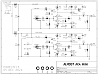
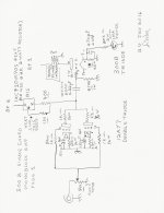
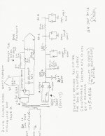
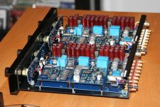
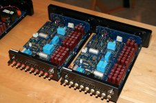
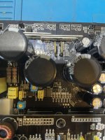
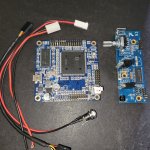
For my own use, I created an "almost cloned" version of Nelson Pass's PCB layout for the ACA Mini power amp. Compare my layout to Nelson's, you'll see I did not make an exact copy

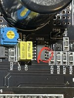
  • Mine uses 45-degree angles; Nelson always avoids these
  • Mine rotates the big capacitors by 45 degrees. Why? Because I can.
  • Mine has a much wider ground buss on the bottom copper layer
  • Mine includes a "stack" of 5 resistor bodies; Nelson's "stack" is only 4 resistors
But, overall, my board is similar enough to Nelson's that I'd call it an Almost Clone.

I ordered a bunch of these boards from a PCB fab, and don't expect to use all of them myself. So I'll be giving away my extra board for free -- I'll even pay the shipping. However I'll only give them to diyAudio members that meet a couple requirements:

  1. Ship-to address needs to be inside United States // no international shipping
  2. Recipient needs to recognize: this is an untried prototype PCB, and may have issues (even despite passing Layout-vs-Schematic verification software)
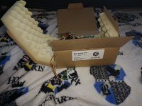
  3. Recipient needs to have already ordered the high value parts (JFETs, MOSFETs, heat sinks, snap-in electrolytic caps). Be ready to email a photo.
  4. Recipient needs to have plans to complete the ACA Mini Almost Clone before 15 January 2022 -- and must be able to convince me they're an enthusiastic builder, not a mere hoarder of blank boards

So, if that's you, send me a Private Message, and address each of the four requirements above. I'll wait a week or two, collecting the PMs, (since plenty of members only look at diyAudio once a week), and send out my replies. I expect to get PCBs back from the fab some time around 17th Dec or so.


ANSWERS TO FREQUENTLY ASKED QUESTIONS

Will I give away my Gerber files? No. The ACA Mini will eventually be sold in the diyAudio Store and you can buy it there. This board is only a stop-gap, temporary measure, while everyone waits for the official Store product(s).

Am I willing to ignore the four requirements above, just for you, and sell/give you a board anyway? No.

Do I know anything about the schedules, prices, or future plans of the diyAudio Store? No.


(... room for further expansion as new inquiries arrive ...)


_

Attachments

  • Whole_Board.png
    Whole_Board.png
    122.2 KB · Views: 1,173
  • schema.png
    schema.png
    96.4 KB · Views: 1,150

LatFet Amp Based on Philips AH578

Here is a little, simple amp that turned out to be easy to build,
and with decent parameters.
It's based on Philips AH578 (which was a quasi amp), originally designed by Earl Rapp, but built with modern devices (LT1056 op-amp, Exicon dual-die FETs). Rails at 45V.
All screenshots taken with 8 Ohm load.
DC offset at the output: 2mV, and stable.
Idle current: 80mA per device.

PCB design: post #13
HexFet version of the amp: post #124
PCB design for HexFet version: post #130
Push Pull HexFet version (fast and stable): post #1
...

Attachments

  • philips22ah578.jpg
    philips22ah578.jpg
    232.4 KB · Views: 3,226
  • 1khz_thd.png
    1khz_thd.png
    23.5 KB · Views: 3,067
  • 1khz_fft.png
    1khz_fft.png
    19.6 KB · Views: 2,283
  • sinus_1khz.JPG
    sinus_1khz.JPG
    235.8 KB · Views: 2,149
  • sinus_34khz.JPG
    sinus_34khz.JPG
    225.4 KB · Views: 2,000
  • sinus_100khz.JPG
    sinus_100khz.JPG
    241.1 KB · Views: 596
  • square_1khz.JPG
    square_1khz.JPG
    241.2 KB · Views: 612
  • square_14khz.JPG
    square_14khz.JPG
    229.9 KB · Views: 646
  • square_34khz.JPG
    square_34khz.JPG
    232.6 KB · Views: 1,435
  • philips22ah578.asc
    philips22ah578.asc
    10.4 KB · Views: 262
  • Like
Reactions: sulcorebutia

Soldering tweezers

Any recommendations for good soldering tweazers for SMD components I stupidly managed to fit polar caps around the wrong way (on the -ve voltage side) and believe I need to replace a couple of these resistors as I believe they might be blown on one channel. All the caps are replaced the right way round and only one channel is in need of attention, so a lucky break

I'm okay soldering larger pads and some smaller stuff but trying to remove and replace these is looking in need of better equipment

IMG_2090.JPEG

Headphone amp using 6SN7 + 6080?

Apologies in advanced for my noob questions.

I'm looking for a schematic, or possibly assistance in modifying an existing one, to build a headphone amplifier using 6SN7 and 6080 tubes. I have a quite a few NOS RCA 6080's laying around along with a few 6SN7/12SN7's (and a few 6SL7GT's, not sure if they're useful for this).

I've seen various preamps utilizing the 6SN7, and I've seen a tubed headphone amp schematic on headwize using a 6922 + 6080/6AS7 I assume for gain and as a cathode follower, respectively. I'm not sure if I can just plug the cathode follower on to other schematics (I'm still learning/trying to understand tube design.. Please forgive me 😉

I've also thought that maybe paralleling the triodes of the 6080 for more current drive might be desirable, since I'd like the amp to be usable with my grado cans as well has my AKG and Sennheisers.

I know there are a few commercial designs out there using the 6SN7 for the gain and paralleled 6080's for the output (I believe that one of them uses an output transformer as well). I'd like to try it OTL first, and then maybe move on to investing in iron if the performance gains would be worth it.

Any suggestions or pointers or schematics would be most helpful!

Thanks,

M1

j50 k 135

Got me plenty of those and actually dont know what to do with them
My gut says that no mater how i operate them , they will never beat the 1302-3281 combo .

so ok got a secondary set of 2way speakers that i would like to operate in reality those are sensitive 30W real power speakers so power of the amp is not the issue .... one pair of those will happily produce 60 W ...

so the idea is to go for something diferent How about a tube mosfet combo and highly biased ?

has anyone seen a schematic like that that operates with these transistors ?
if so please let me know

Other suggestions are also welcome but still i think what ever this should be in high bias

Mullard Reissue cryogenically treated matched quad of EL34 tubes from Upscale Audio

SOLD

I purchased these as lightly used from the original owner. They came from Upscale audio where they were quad matched and cryogenically treated.

Mullard Reissue tubes from Russia are not being imported at the present time.

I retested after purchase on my eTracer computerized tube tester. I have sold the amp these were to be used in, so they are for sale. These have not been used again after the retests noted on the boxes in the pictures.

Tubes come in their original boxes with the Upscale audio and my testing data on the boxes.

I will ship via USPS Priority Mail insured only.


IMG_0983.JPGIMG_0984.JPGIMG_0985.JPGIMG_0986.JPGIMG_0987.JPGIMG_0988.JPGIMG_0989.JPG

Acoustat "The Monitor" speakers

I purchased these at an Estate Sale a week ago. I couldn't leave them behind as literally they were going to a warehouse for an unknown amount of time in 15 minutes.
My intention was to find a home for them since they are much to wonderful not be enjoyed by someone.

They work wonderful.
I pulled out an Aragon 2004 amp from my HT and borrowed a modded Onkyo pre from a friend. I hooked them up yesterday and sat for 3 hours listening.

Thankfully, with the help of Acoustat Answer Man and mraudioguru.

They don't have the original Tube Servo Amps but the MK121-2a interfaces have the "C" Mod and Medallion Transformer. gives the Blue and Red Medallion upgrade to them using later transformers. Stickers on the interface designate the upgrade.

They are in great shape. The Mahogany wood trim has a couple of small dings that I will post picks of later.

I'm asking $1000 for them and must be picked up here Wesley Chapel Fl. just north of Tampa.

I'm Brad and you can reach me at brock24252425@yahoo.com if interested.

Attachments

  • IMG_1918.jpg
    IMG_1918.jpg
    182.2 KB · Views: 391
  • IMG_1901.JPG
    IMG_1901.JPG
    734.3 KB · Views: 291
  • fullsizeoutput_bad.jpeg
    fullsizeoutput_bad.jpeg
    527.3 KB · Views: 227
  • Image 8-20-22 at 12.49 PM.jpg
    Image 8-20-22 at 12.49 PM.jpg
    90.5 KB · Views: 169

How do I know a transformer is shorted?

Hello everyone! I have a shelved Rockford amp it's a punch 500a2. The problem is the mosfets for the power supply keeps shorting! I have replaced them probably 3 or 4 times already. I checked out all the solder connections on the mosfets no bridges I always make sure it's clean. Before it failed I can here a clicking sound in the transformer and the music would pause on each click the transformer would make. I have checked all the output fets to make sure there isn't a short in any and they all test fine. I don't want to waste anymore of my little stock of fets on this amp. I'd like to find out what's causing this if possible.


Oh yeah the fets are IRF3205 & the gate resistors are all 47 ohms.

USA amps MD 1D

Hi all
Amp came with burned power supply. 70n06 mosfets with 47ohms gate resistor and two pnp A1266 drivers. I changed them with 3205.
Amp is pulling too much current on idle. I removed mosfets belongs to one transformer the other transformer that is producing small voltages works good Amp came on and gave good output oscillations.
But as soon I replace mosfets for next transformer amp pulls plenty current. I removed one mosfet from each bank of the same transformer and amp works good. So it driving 2x2 mosfets good but can't drive 3x3 mosfets. What I can do to solve this issue.

Help DIY newbie: can I mix drivers with listed 6.4Ohms Imp. with 8ohm drivers in one speaker?

In this case its Kartesian drivers, they have many driver models with Imped. stated very precisely, like 4.9Ohms, 6.3, 5.5 etc.
Other brands mostly say its either 4, 8 or 16 ohms.
So now I wonder, should I round it to nearest 4 or 8? or just beware not to mix too WIDELY different impedance drivers?

The other similar question i have: what is the maximum tolerable difference in drivers Sensitivity within one single speaker?
For example, when one is 86dB (high midrange) and woofers are 96dB - is it too big gap?

I see some commercial models which mix 87dB woofers with 93dB AMT tweeters.....

For Sale FS: PAIR of NEW matched JJ 300B tubes.

As you can probably guess from the other items I have listed, I wanted to build a 300B SET amp but never got around to it. Then came unfortunate family events and job loss.

For sale is a matched pair of JJ Electronics 300B tubes. These are NEW and have never had any voltages applied.

$310 for the pair plus shipping. Located in St. Louis, Missouri.
IMG_2569.png

3'' mass loaded transmision line

Hi, I my first project has been a pair of small columns based on FaitalPro 3FE22. They were based on the AMLTL theory found in this post: https://www.diyaudio.com/community/threads/accidental-mltl-technique.231951
The volume was chosen based on simulations done in WINISD making the bass reflex tunning slighlty lower than optimal 90Hz or so, and then the dip in the mid bass was improved tunning the TL to 150HZ.
They ended up sounding quite good, I was not expecting that much bass for a 3' driver. The soundstage is really good, bass is lacking if they are placed on a table/shelf, good on the floor and almost too much near walls.
Bass Reflex port is rear facing so that front baffle can be bigger, I suppose this would be good, and also this placement was chosen so that any resonance is less heard.
The final version is more stuffed than these and the lateral has been glued for good. Now I am working in a 3 way design.
I want to thank eveyone in this forum, there is really valuable information.
Regards

hornresp1.JPG
hornresp2.JPG
Lateral vacio.JPG
lateral stuffing.JPG
final.JPG

Tube Amplifiers I have modified, designed, and built

I have had requests for me to post some of my tube amplifiers. I will do a few of them in this thread.
I will do my best to answer questions about the amplifier as they come up if it does not take too much of my time.

Here is an amplifier I built years ago, and which was also built more recently in Japan by an 'Across the Ocean co-worker.

Two stage single ended 300B with parallel 12AY7 driver.
The amplifier and power supply schematics are attached.

I hope you like it.

Attachments

  • SCAN2074.JPG
    SCAN2074.JPG
    190.4 KB · Views: 385
  • SCAN2075.JPG
    SCAN2075.JPG
    231.2 KB · Views: 384

Does this forum software include "thread tools"

I have a fuzzy memory (that may be incorrect) from the previous forum software of "thread tools". I think one of the features of these tools was to "ignore" a thread, such that it would never appear to the user again. Sort of like "block user" but for an entire thread. I could really use such a tool right now! Does the current software offer anything like that?
  • Like
  • Thank You
Reactions: jan.didden and PRR

Solar powered sound system.

Hello all. Hope everyone is well.

I'm hoping for some advice and some pointers in the right direction for a project I have in mind.

So I have a narrow boat and I have created a pretty decent solar array/battery setup and now I want to build a nice sound system.
I am looking to build a mini stack comprised of a subwoofer, kick/midbass unit, a mid box and a tweeter array.

currently I'm focused on the subwoofer and truly I am overwhelmed! I Want something that can go deep and as loud as possible, but I'm limited on both power and space for obvious reasons.

The limitations are a box not much larger than 450mm by 1000mm by 800mm and I have around 600w (RMS) to play with.
so with this in mind Im thinking I want to build some kind of horn with a 15" driver. However there are so many types of horns and drivers I'm getting a bit lost.

I'm mostly in to bass heavy music like dub reggae and drum and bass etc so I want it to deep and powerful. I intend to have small parties outside, next to the boat with a 100 people or so, therefore I want it to be fairly loud, yet I want to use it inside just to enjoy so I want it to be controlled and not just a boomy mess.

I know! I want it all 🤣 but I think something decent possible as I'll have another 450w set aside for the kick speaker and I can prob cross over at 70hz or so, hopefully leaving more power to get down to at least 30hz

I Have narrowed the driver down to 3 that I think could fit the bill based on what I can get hold of in the UK.

Guys please share your wisdom and let me know your thoughts. Should I go with one of the following or something else? And based on the choice of driver which type of horn should I research and ultimately build.

the drivers I'm looking at are the LAB 15 (although being 6ohm limits power a little more), the [/B]Dayton Audio UM15-22, the Dayton Audio RSS390HO-4 or the B&C 15SW115-4

Using TDA 7293 IC on a 7294 Board.

I was under the impression that the TDA 7293 and 94 are similar and that the only difference is that the 93 can handle higher voltage. And has a clip indicator.
Was also told that the chips are interchangeable i.e. if the circuit runs a 94 you can replace it with a 93.
So purchased a PCB for the 94. Built it and powered it up to test at very low voltage of 15-0-15 1 amp. Just to make sure nothing blows.
And it blew. No input or output was hooked up. Just the power supply. One unit exploded and one just got really hot. (Single PCB stereo setup)
After a few hours of study. Its apparent that the chips are not compatible. And that on the 93 you need to populate the boot strap part between pins 6 and 12. As well as adding a cap between pin 6 and output. A circuit that runs the 93 can run the 94 but a 94 circuit cant run a 93 this is what somebody told me.
Im now down to my last 2 93 ICs.
So thought I should check with you guys. Could this be the reason my chip blew ?. Or is it more likely that it was just a fake chip. The chip was sourced from Duabi. And I suspect the guys in Dubai sourced it from China.
Am reading up on the bootstrap most people recommend replacing the 22 uf cap between pins 6 and 12 with a 47 uf cap.
I have some TDA7294 ICs which look fake as hell but they work fine. Just cant find a source for good 94s so imported the 93s from dubai.
Any other tips for or common pitfalls that pop these ICs. As always found a wealth of info on this forum. Still reading up.
Found this link to be useful.
https://www.easybom.com/blog/b/tda7293-vs-tda7294-audio-power-amplifier-what-is-the-difference
https://en.wikipedia.org/wiki/Bootstrapping_(electronics)
Just trying to figure out if the lack of the boot strap components could result in the IC failing. If yes good. Will add the boot strap bits. If no then I have to start from scratch and recheck everything.

Mystery Mission 760i failure

I bought a pair of Mission 760i speakers a few months ago from UK Ebay.

After like 2 months of having them, one of the speakers suddenly started putting out this ugly sounding air current through the front port, its like a crackling noise. It sounds the most obvious at about 50Hz in tone generator, but the crackling sounds higher pitched than the bass coming out and the crackling noise disappears if i lower the volume enough.

I have sent the broken speaker to two different places to fix it, before troubleshooting them myself because i was lazy and thought i didnt have the expertise/confidence to do it myself.
The first guy thought it was the woofer fault and took apart the woofer and changed the coil because he said it was deformed/ egg shaped or w/e, but it didn't help the crackling noise, its still there.
The second place told me its the faulty tweeter that's causing a vibration. They fixed nothing and charged me 20euros for trouble shooting.

After i got it back from the second place, i had built up the courage to troubleshoot and take them apart myself.
So, I tried switching every component(woofer+tweeter+xover) of the crackling speaker with the normal sounding one. And the crackling noise still persists in the same broken speaker. I tried taking out the dampening foam from the cabinet but it didn't help.

I ordered film caps, but they wont help as i have already switched the xover from the good speaker and it didn't help.

Is there anything else left to try?

Wiring for open baffle

Hopefully this is the right area but if not feel free to move it. Each of these baffles has four 4ohm drivers wired series parallel for a 4ohm load per side. Is it okay to then wire them both together in series for an 8ohm total load to connect to a single plate amp? I'm a bit new so want to be sure. Thanks!

Chris

Attachments

  • 20220805_171923.jpg
    20220805_171923.jpg
    638.2 KB · Views: 101
  • 20220805_164312_HDR.jpg
    20220805_164312_HDR.jpg
    622.8 KB · Views: 104

Help with DIY 2.1 channel desktop speakers with 5 or 6 speaker mini line array as satellites

So I'm about to start my first diy build. I have a TPA3116D2 2.1 Channel amp and I ordered a lot of 12 Boston Acoustic drivers from the satellites of old BA635 2.1 computer speakers. They are 2" full range 4 ohm. I have a few options at home as far as suvwoofer drivers, or I might buy one, but first I want to decide on how to build the arrays. I have access to woodworking tools and some woodworking knowledge. Budget is tight, less than$100 to get everything else I might need.

I've been reading about the different styles of array and there is so much information my head is spinning. I was originally going to build 4, 5, or 6 driver vertical line arrays for the sats but now I think I'm leaning towards a bessel array. Or maybe a horizontal array, soundbar with subwooer. Will the lack of tweeters hurt the quality of my build significantly? I'm not opposed to adding some but need some guidance on selection and building crossover. If I go with the vertical (or horizontal) line array I can wire 3 pairs in series (down to 2 ohms) and wire the pairs in parallel for a 6 ohm load. I can wire 2 pairs in parallel and wire the pairs in series for a 4 ohm load. Or I can use 5 drivers and I'm not sure what amp load that would give me. Please any advice or recommendations would be much appreciated.

Gryphon XT-MC for sale/swap

Good evening all,

after many years of faithfull service my Gryphon XT-MC preamplifier is surpassed by my new DIY preamp based on the Philips MRO PT8 triode (Philips MRO PT8 preamplifier ). And now that Gryphon is collecting dust which is a shame because this preamp is still a great piece of audio gear.
It is one of Gryphon's earlier designs containing all the options. You could buy this as a XT (line only), XT-MM (including a phonostage) or as the XT-MC (including both the phonostage and a headamp). This one is a XT-MC and that phonostage is really good. Of course i like DIY but if you must buy commercial the execution of a Gryphon is top notch.
Gryphon: so really executed double mono with dedicated power supplies. They even have 2 power cords ! Only the frontpanels are stereo....

Included the package of load resistors (MC-stage), manual and power supply umbillicals.

Yes: you can note some scuffmarks but nothing really shocking. It's not new !!!

Do send an interesting bid ! I'm fully open to a swap of components, (compression) drivers, MC cartridges, field coils, etc. Again: do an interesting bid.

I live in the Netherlands near Arnhem close to the German border.
Looking forward to you bids/offers.
Regards,
Reinout

Attachments

  • DSCN1895.JPG
    DSCN1895.JPG
    357.5 KB · Views: 670
  • Gryphon pic 1.JPG
    Gryphon pic 1.JPG
    384.9 KB · Views: 736
  • Gryphon pic 2.JPG
    Gryphon pic 2.JPG
    94.2 KB · Views: 731
  • Gryphon pic 3.JPG
    Gryphon pic 3.JPG
    77.5 KB · Views: 759
  • Gryphon pic 4.JPG
    Gryphon pic 4.JPG
    450.2 KB · Views: 724
  • Gryphon pic 5.JPG
    Gryphon pic 5.JPG
    141.7 KB · Views: 868
  • IMG_5494.JPG
    IMG_5494.JPG
    286.7 KB · Views: 602
  • DSCN1854.JPG
    DSCN1854.JPG
    415.3 KB · Views: 529
  • IMG_5473.JPG
    IMG_5473.JPG
    87.6 KB · Views: 707
  • DSCN1863.JPG
    DSCN1863.JPG
    595.8 KB · Views: 540

Abletec / Anaview ALC0300-1300: DC offset, high-pitched noise, no sound

I bought two NOS ALC0300 recently to make a stereo amp. One worked perfectly -- it sounds great and the DC offset is only 18mv at the output. The other not so much -- DC offset is a constant ~400mv, there is a high-pitched sound coming out of some components (i.e., from the amp itself, not the speaker), and the there is no sound output, all regardless of whether the signal inputs are open, shorted, or connected to a source. It feels like that the amp is in protection mode or standby mode after being turned on.

I checked all wirings and could not find anything -- all continuity/impedance readings between the two amps are consistent with each other, and the two amps are housed in the same project box with similar grounding arrangement. I disconnected the working amp, and nothing changed with respect to the non-working one.

Any thoughts? Thanks!

Testing mic - simulating a capsule

Hey there,

While a capsule replacement is being considered on a LDC mic (AT4040),, would anyone have an idea about inputting a signal into the inputs of a mic for analyzing the output? this is just to prove that the circuitry is performing the way it should. The input of a microphone somewhat eludes me due to knowing of the high impedance and phantom power to the capsule.
thank you,

Phil D.,
  • Like
Reactions: Pano

DC brick powered TPA3118 hums with a guitar.

I have one of these boards (a clone of the TI example) running from a guitar preamp and it sounds great to my ears. BUT... it hums when I have the guitar volume turned up (magnetic pickups). No hum with guitar volume at ZERO. I was initially thinking it was my cables, but I noticed that when I unplug the supply (24VDC switch mode brick) the hum goes away for a second and the signal comes through just fine until the filter caps discharge.

So I'm thinking PSU issue.

But... is there something I could be overlooking? Do I need to just add more filtering?

NAD C-275-BEE- in protection amber mode (EM78P153SP controller)

Hi, everybody !

I need some help to understand why the unit is in amber protection mode (not red protection mode).

If soft clipping activated -> start flashing soft clipping LED.

Outputs checked as diode, seem ok all of them.

Amber protection mode also if left channel & right channel disconnected (all 3 plugs - main voltages - input - subsidiary voltages)


Voltages on controller:
EM78P153SP
Pin-08 P62/TCC signal enable-out 0_
Pin-09 P61 switch_enable-out 0_
Pin-10 P60/INT thermal-in, 5 V = ok 5.5
Pin-11 Vss Vss 0_
Pin-12 P53 trigger-in 4.8
Pin-13 P52 signal-in 4.8
Pin-14 P51 protect 0_ (0 in protection mode ?)

Pin-07 P63/RST Reset 4.4
Pin-06 P64/OSCO ON/OFF-in 4.4
Pin-05 P65/OSCI trigger enable-out 0_
Pin-04 Vdd Vdd 4.4
Pin-03 P66 amber 0_
Pin-02 P67 MUTE-out 4.4
Pin-01 P50 STD_BY-out ? 4.4

service-Nad-C-275-BEE-Service-Manual_08-MB SCH-01.jpg
service-Nad-C-275-BEE-Service-Manual_10-Display SCH-01.jpg
service-Nad-C-275-BEE-Service-Manual_10-Std-BY SCH-01.jpg

  • Article Article
My life in DACs: a catalogue of failure

For posterity, here's my experience with digital-to-analog conversion. It's been a long road to nowhere, but since my primary source was analog anyway it didn't concern me overmuch.

Audio Alchemy DAC-in-the-box. Cheap and serviceable, I had no complaints at the time ... which was a very long time ago now.

Onkyo SE-200 PCI soundcard. This was my digital front end for long time, and I really liked it. Lack of hardware support for PCI bus, and lack of driver support for modern Windows meant I had to give it up. Don't knock this card - it has some serious engineering prowess under the hood.

47 labs Treasure 0247 headphone amp, which happened to have a little USB DAC add-on board. The DAC itself was a complete afterthought, a single chip affair that promised nothing and delivered very little.

Objective2 ("O2") or ODAC. Very briefly ended up with one of these for evaluation. Distinctly meh.

nuForce uDAC. Yuck.

Onkyo SE-300 PCIE soundcard. The short-lived successor model to the SE-200 sporting not only a PCIe interface but a completely new chipset based around an audio processor from Creative (aka Soundblaster). The switch was a mistake in my opinion. The overly processed sound had none of the magic of its predecessor.

Orb Jade-1. A low-mid-range artisanal Japanese headphone amp / DAC. Tight, pinched, cold sound. Didn't care for it.

Asus Xonar STX soundcard. This replaced the Onkyo, and has been my reference for some time now. Not the last word in resolution, nor does it have the musicality I would like, but it has enough swing and verve to keep me engaged.

[For color, I'll add this one too: the Lenovo USB-C -> 3.5mm dongle that came with my Duet tablet, which I use with my Sony MDR-1A headphones. Is it wrong that I have no problems with this sound? Because it's surprisingly fine. Then again those headphones sound okay plugged into anything. Never superb mind you, but never terrible either.]

Korg DS DAC 10. This was expensive enough for me to think it might be worth trying but cheap enough for me to actually give it a shot. Unremarkable. Grey and lifeless.

Ayre Codex. I like the DAC, but I can't extract the signal before it gets muddied up by the dual-purpose headphone/line output circuitry.

S.M.S.L. Sanskrit 6th. Rare that such objectively good sonic characteristics - very low noise and exceptional detail resolution - should end up so plodding and incoherent, but this is the case here.

And now, the latest attempt: last week I bought a Chord 2Qute which will arrive shortly. Fingers tightly crossed that this will be "the one" to outshine the Asus Xonar.

Tentlabs low noise negative bias psu

For sale like new module, used once for short time in original package. Price 120 euro including registered and insured shipping inside EU!!! Payment paypal for friends!

Attachments

  • IMG_20220823_103946.jpg
    IMG_20220823_103946.jpg
    349 KB · Views: 168
  • IMG_20220823_103943.jpg
    IMG_20220823_103943.jpg
    392.8 KB · Views: 127
  • IMG_20220823_103946.jpg
    IMG_20220823_103946.jpg
    349 KB · Views: 126
  • IMG_20220823_103950.jpg
    IMG_20220823_103950.jpg
    373.6 KB · Views: 158
  • IMG_20220823_103938.jpg
    IMG_20220823_103938.jpg
    416.9 KB · Views: 165
  • Like
Reactions: invaderzim

S.M.S.L. M8A bugfix

Hi all. Recently a quantity of leftover Chinese stuff was dumped on the market here and there was 2015 - 2019 produced audio stuff in the lot. I got hold of a few SMSL M8A DACs at a nice price for friends. Beautiful and very small solid aluminium milled casing, XMOS Xu308 and a ES9028Q2M with 3 x OPA1612 for filtering and one of those marvels of modern technology an SMPS wall wart. Except for the switcher nothing can go wrong I thought. After connecting the others and myself found the bass to be very light and the general sound character was so so. Even my old Subbu V3 was way better. I hadn't bothered with recent ESS DACs and was looking after every corner for the horrendous ESS hump and all the nasty stuff people tell about ESS DAC chips that are supposedly acoustical hell. Scary stuff and no TDA chip nearby to cure the ΔΣ pain.

How come? Layout looks OK and part quality seems good too. Most reviews in English were very positive about this very DAC. Did we receive duds or fake ones? Not likely as they came from the distributor and were in original packaging. Are we spoiled and used to extreme good audio?! Also not likely. Are the reviews questionable? Mmmm...they are!

We found the device not delivering what we expected so I examined all details. I replaced an opamp, replaced the 3 pieces 470 µF 16V Panasonic FJ (old series) for FR etc. Still it did not perform. Is it that darn switcher SMSL uses for creating +/- 12V?! No. Then I looked a bit deeper and the bug & error hunting paid off. The regulator for the 1.25V for the ES9028Q2M DAC core was not so stable sometimes going to 0.9V. It is a LM317M in SOT-223 and it gets its 3.3V input voltage from a 3.3V pre-regulator.

Wait a minute... LM317M putting out 1.25V so ADJ pin to GND and 3.3V input voltage?!? Right there lays the issue. A recent LM317M needs about 2.5V differential voltage at 500 mA and this is an absolute minimum. All datasheet values (depends on brand) are specified at 3V. Many will now tell me that the dropout voltage depends on the output current and it sure does. But ... the core current apparently is not a stable value and it sometimes fluctuates to even a few hundred mA. Then the dropout voltage is between 1.7 and 2.5V strongly depending on brand. Let's say it is running more than 200 mA then dropout voltage is already 2.1V with the LM317M as used in my DAC. 2.1 + 1.25 = 3.35V... while it has a stable 3.3V offered at its input. Won't work out OK.

I replaced it for a AMS1117-ADJ with only 1.3V dropout voltage at its maximum 800 mA. Bingo!!! The DAC at once performed like it should with solid bass and very good sound stage. I'll save you the "veil lifted" and "blacker than black" talk as in the reviews but the device is totally different from the old situation. An amazingly large difference.

Nothing found on the web about this bug so I'll publish it here so you can mod your M8A too. So get your M8A and do the less than 1 Euro costing modification. You won't recognize it the second you will use it again. Highly recommended.

On the picture it is the SOT-223 regulator left of the "M8A" marking. It is already the AMS1117, I forgot to take a picture when replacing the LM317M.

Attachments

  • IMG_3549.jpg
    IMG_3549.jpg
    600.8 KB · Views: 409
  • smsl-m8a-usb-dac-es9028q2m-32bit-768khz-dsd-xmos-xu208.jpg
    smsl-m8a-usb-dac-es9028q2m-32bit-768khz-dsd-xmos-xu208.jpg
    24.5 KB · Views: 400
  • Like
Reactions: jan.didden and TNT

Yamaha RX-V 2300 Receiver turns on & then turns off within 1 second. DIAG displays: TMP PRT: 311 F

Receiver turns on then off within 1 second. When starting amp diagnostics DIAG the history of protection function displays TMP PRT:309 F.
The protection function worked due to the temperature limit being exceeded.
Causes could be a defect related to the thermal sensor. Temperature detected value(Normal value: 51 to 158)
I measure thermsistor input is 5.25VDC, output is 3.23VDC. It is seem that output is higher normal value. Could anyone
help me solve this issue?

JL 1000/1 rev11 (Good updated FETs for both sections?)

So I just got in another JL 1000/1 rev 11, guess it’s been sitting a few years since owner sent it to Ohio, got it back, only lasted an hour 🥴

What are considered the best updated replacements for this amp/revision?

What are the stock FETs for this amp, and are those preferred?

In the process of gutting it now, both sections blew/melted 🤯

Attachments

  • 036CFC96-336D-4960-BB6D-909F96EBBEDD.jpeg
    036CFC96-336D-4960-BB6D-909F96EBBEDD.jpeg
    470 KB · Views: 117

WTB PEERLESS SLS 830668

Hello. I am on the hunt for a Peerless SLS 830668 driver. I got a good deal on a single one the other day, and one like another to make a pair for a pair of speakers. I only need one, but would be open to buying 2 if need be. I'm thinking maybe I could make a small powered subwoofer with the spare, but buying just one would be ideal. Thank you!

Mono tube pre stage for Class D board

Hi all. I have started purchasing the bits required to build a set of powerful full range active speakers using a mono IRS2092 board. I would like to implement a tube pre stage on each speaker for tube flavour as well as extra gain (will use the gain for amping instruments in a different active speaker)

Would like to run a tube preamp type stage before the input of this board so that the audio signal coming to the active speaker picks up tube flavour and not sure whether to fit a stereo preamp board with channel one feeding into channel two via a pot or to instead build a mono channel from a tube headphone amp and use the output from the output transformer to feed the class D board input. I am not sure which approach would best for tube flavouring and would appreciate some help with this

I can see some attractive preamp options using 6N3/5670 and 6N8P tubes as well as 6P1

Need help starting out with which tube approach please

Thanks and regards
Randy

300B early distortion desired

Hello to all forum members. I am looking for a 300B amp design that will go into the so-called euphonic distortion early (but non-destructive)

I am also looking for a circuit to pick up the 300B speaker output and produce 2 channels of biampable line level signals to further amplify the result into class d

The 300B amp will be hooked up to a pair of pioneer coaxial that are very inefficient but go very low for night mode for monitoring and the class d stage for daytime when I can let it rip. I will also be occasionally stereo mic-ing the pioneer speakers when recording, but 90 percent of the use of this system will be the front channels of a smallish nighttime general music and video playback

I don't really care for purity all the time, I enjoy "effected music" and love the overdriven 300b sound

Thanks and regards
Randy

Amp Choices to 1kw

Hello all to forum members. My only experience with class D are car audio amps from JL Audio, but I am familiar with messing with amp modules from the pre-class D era

I have a low frequency driver that has dual voice coils, and each coil is rated 200wrms and 4 ohms. The driver is rated 400wrms, so I assume it's 400wrms at 8 ohms in series or 400wrms in 2 ohms in parallel, also rated 800wmax
I am open to increasing driver count to 2 if it makes for a better combination with the amp I end up with. The drivers will be crossed at around 600hz for a specialist build

I always prefer to have ample power headroom, by which I mean that I prefer to utilise an amp larger than the speaker power rating and I also prefer to under use an amp to achieve the power I want rather than run amps at their output limits. I will be using a power supply with ample headroom

I am unable to find any internet published benchmarks that test the better TPA3255 boards with well rated power supplies. Everyone seems to review with PSUs that seem inadequate
Please point me towards any reputable reviews if anyone has crossed paths with one

Maybe TAS or TD series?

At the moment, I am leaning towards two IRS2092 basic boards, one to drive each of the dual coils. I am also looking at the higher rated 1000w mono and stereo channel IRS2092 boards

So in summery;
400wrms plus in 8ohm
or
Two x 200wrms plus in 4ohm
or
400wrms plus in 2 ohms

or
800wrms in 4 ohms for twin driver with driver VC in series and drivers in parallel for total 4ohm load

Looking forward to the forum suggestions. Budget for amp and PSU is around $150AUD

Thanks and regards
Randy

JL Audio 500/1 rev11 (Output Section Problem)

So amp had a power supply blowout, removed blown FETs, confirmed I had drive, replaced FETs and amp cycles between low current quickly climbing to constant current mode on PSU, removed rectifier and again have clean switching to rectifier pads, then I find a small piece of metal between legs 9&10 on U502 (LM391M) can’t believe I missed that :/ so I reinstall rectifier and remove output FETs (which all test good) and current is still climbing fast maxing out PSU (I have limited to 3.5a) to CC mode. No waves of any kind on the U500 (4427) U501 (2068) U502 (319)

Any insight greatly appreciated, not the best with JL Slash amps but getting better 🙂 hoping the JL guru sets me in the right direction 🙏🏻

Attachments

  • EC031F92-6A2A-4528-860E-666626B248AE.jpeg
    EC031F92-6A2A-4528-860E-666626B248AE.jpeg
    714 KB · Views: 112
  • D5E9C90E-F962-458B-8D43-9785D369A789.jpeg
    D5E9C90E-F962-458B-8D43-9785D369A789.jpeg
    485.2 KB · Views: 121
  • DEA412E8-A0B9-47A1-8C33-339EB5EB9825.jpeg
    DEA412E8-A0B9-47A1-8C33-339EB5EB9825.jpeg
    388.2 KB · Views: 128

Classix II Crossover

Hello,
Been trying to put together the crossover for Paul Carmody’s Classix II but have had some trouble reading the schematics.

Not the prettiest soldering job but its honest work.

Would you say this crossover is correct?

Attachments

  • 91856739-6768-4CE8-99EE-9C398733FA91.jpeg
    91856739-6768-4CE8-99EE-9C398733FA91.jpeg
    640.8 KB · Views: 159
  • 2703A3AF-9756-48F7-B105-55613290E26F.jpeg
    2703A3AF-9756-48F7-B105-55613290E26F.jpeg
    653.9 KB · Views: 153
  • F2E378E6-CB70-4FA9-A4ED-C4DCAEC8037E.jpeg
    F2E378E6-CB70-4FA9-A4ED-C4DCAEC8037E.jpeg
    39.4 KB · Views: 167

Polytone Mini Brute II

Is there anybody out there who has access to, or can tell me, where I can find the schematics for The Polytone Instruments Co.
Mini Brute II guitar amplifier.

I found one at a garage sale for nothing, however it's missing the 12" speaker, and there's a problem with the power amp.
My friend said he'll repair it for me for the cost of the speaker and if I found the schematic for it.

I think the one I own is the early incarnation of this amp, The Murch Music web site (Polytone page) shows 2 user manuals (early + contemporary) no sign of a schematic on their site however.

It would be nice to have access to both schematics to see if it's easy to bring mine up to the newer specs.

I'm currently running my bass through a vintage Garnet LiL'Rock
bass amp(taller version with sealed back) which is getting to heavy for this 50+ boomer to be schlepping around.

The Bottom Line bass newsletter has some references to using the Mini Brute II for bass even though it is a guitar amp.
Apparrently Polytone made a Mini Brute bass amp.
I'd be interested in a schematic for this amp too if any one can help.

I'd appreciate any help on this........................

Thanks...................Fred Petersen

www.audiofileoptions.com

Faraday sound diy concrete booklet

Can anyone help with this, please -

Awhile ago, Faraday Sound in Norwich, UK had a book available that contained information about Low Density Concrete for diy projects - they appear to be now defunct and maintains no working web addresses.


I found 2 addresses from Google - "Faraday Sound,248 Hall Rd, Norwich, NR1 2PW, UK"
and - "Faraday Sound, 38 Cricket Ground Rd, Norwich, Norfolk, NR! 3BQ, UK"

Is there anyone that may have this information, or know of the book, or even know what happened to the Faraday guys?

Rockford Fosgate Punch Power 200a1 trouble shooting / Schematics

Hello!

I am working on this amp, it powers up and pulls 0.4amps. LED is lighting. Turning bias doesnt have an effect on idle current.

I have 33Volts DC on the speaker terminal.

Rail voltages are +- 38 VDC.

D7 was short.

I had positive Voltage on all preamp- opamps pin 4 which should be negative.

I changed both voltage regulators ( LM 337 and LM 317 ) , now its -30VDC on pin 4 and -2VDC on pin 8.

Has someone the schematics for this amp?

The board PC number is : PC-2034-D

Thank you very much in advance!

Best regards!
Andi

Selection of opera arias

There are many, I found this one on Tidal that I really liked because of the selection of songs and the performers-
There are famous singers (is it redundant to say "and excellent"?), among others the tenor Luciano Pavarotti and the soprano Renata Tebaldi, whom many considered the "rival" of Maria Callas.
It seems that nobody uploaded it to YT, at least, I didn't find it.

Attachments

  • R-8967319-1644586823-4152.jpg
    R-8967319-1644586823-4152.jpg
    140.2 KB · Views: 112

Full active system plus components - Yard sale!

Got a year till we move house so starting the clear out now!
I will take photos as I haul out the boxes from the loft over the next few weeks.
Finished components include:
Custom Install Audio SM15 - Studio monitors with Beyma 15 inch bass and 5 inch mid/top.
The Mid/top driver is an amazing Rapid Energy Decay (RED) flat coned, honeycomb driver... Crossover at 400Hz and flat to 18Khz!! Super accurate.
Can demo in high end system.... Amazing sound.
Can sell with full system including 4 channels (two stereo power amps - 15Kg each!) of high power / high performance class A/B amplifiers. £200 each.
Can also sell with DBX PA 2 active crossover. £250
These monitors are solid birch plywood laminated sheets ... Totally non-resonant and heavy... 22Kg.... Buyer collects or I can deliver up to 100 miles radius of St Neots PE19.
Two subwoofers (the metalic silver cabinets with Beyma 15 inch drivers) and Yamaha amplifiers.
DIY components include:

Everything from DDFA amplifier module to Beyma 5 inch drive units (16 of them great for line array) Audax drive units, 10 inch Focal kevlar bass driver, Manger drive units (need repair) cables, connectors and cases... Also going to Ebay some kit https://www.ebay.co.uk/itm/Overkill...-amplifiers-150-watts-into-8-Ohm/384909448651 plus see "other items"

Attachments

  • SM 10 and subs, amps & DBX PA 2 crossover.jpg
    SM 10 and subs, amps & DBX PA 2 crossover.jpg
    285.2 KB · Views: 211
  • SM 10 and 15 inch sub.jpg
    SM 10 and 15 inch sub.jpg
    335 KB · Views: 229
  • SM 15 front and rear view .jpg
    SM 15 front and rear view .jpg
    224.9 KB · Views: 189
  • SM 10 side view .jpg
    SM 10 side view .jpg
    297.6 KB · Views: 181
  • SM 15 front and side view .jpg
    SM 15 front and side view .jpg
    331.9 KB · Views: 203

installing hornresp on macbook

trying to install hornresp.net from the internet.
have a macbook running catalina 10.15.7
hornresp will not even download on Safari with a no-can-do message
am running microsoft edge on my macbook
that will download, with no-can-do message.

installed Crossover Mac software, a translator for microsoft language software where the commands are put into mac os language -- wow, it installed
called up the edge dl of hornresp, Crossover Mac loads it in.
Then nothing. Will not run.

Does anyone know what I am missing. I am not a techie and can write an email, but then I am missing in action.

If anyone can help, please do.

Thanks.

Anyone used PVA glues for veneering loudspeakers?

I thought that contact cement was the way to go with veneer on loudspeakers, but it would seem that PVA glues can also be used with a press. Towards the end of this video, they show how.

Login to view embedded media
Basically, a PVA glue with a long set up time is applied to the backer of the veneer. The glue is allowed to "skim over" and then applied to the substrate (MDF). A household iron, set to a "medium temperature" is then used as a platten to set the veneer. The author notes that kraft paper should be used between the iron and veneer so as to not discolor the veneer.

Smaller SS15-style TH (based on brian's POC #3)

Hello,
I have been using the horn folding spreadsheets on diysubwoofers.org to design a tapped horn subwoofer that would fit my particular use case.

Specifically, I'm looking to make a TH that is small enough for permanent residence in my bedroom, but in a pinch can put out enough SPL to occasionally bring out for BBQs and small events (<50 people, anything larger i'd rent). I'd say 90% use would be in bedroom, but for the other 10% would be paired with a single QSC CP12 (HPF @ 80hz), so there's not much needed to outrun the top.

Flat to 50hz or 45 if possible.

Design:
I believe i've some up with something that sims well, but i am new to hornresp and brian's spreadsheets, so i would appreciate if anyone can tell me if there's anything i've overlooked.


I decided to go with the SS15 style fold over the easier to build THAM15. For my bedroom, it's preferable to increase the horn length by adding height rather than depth.

I liked the size of of the POC#3 on diysubwoofers.org, so i decided use the spreadsheets to modify that footprint for a 15" driver.

Would be loaded with Oberton 15XB1200, no particular reason other than it simmed well. I am open to other drivers as well. Thinking of powering and HP/LP with Behringer NX3000DSP

Attachments

  • Small SS15 boxdimen.PNG
    Small SS15 boxdimen.PNG
    2.9 KB · Views: 126
  • Small SS15 boxplan.PNG
    Small SS15 boxplan.PNG
    18.7 KB · Views: 124
  • Small SS15 driver.PNG
    Small SS15 driver.PNG
    9.7 KB · Views: 125
  • Small SS15 Graph.PNG
    Small SS15 Graph.PNG
    4.3 KB · Views: 123
  • Small SS15 hornresp.PNG
    Small SS15 hornresp.PNG
    6.4 KB · Views: 132
  • smaller-ss15.txt
    smaller-ss15.txt
    2.7 KB · Views: 78
  • Like
Reactions: Rik_bS

Which PVA as woofer coating?

This might sound a bit like a dumb beginners question.
I now use Titebond PVA glue for building wooden boxes.
Of the three types which one would be the best to use as a paint on paper cone materials?
I've got a quad of really cheap paper coned woofers here for a proposed OB project and I want to play around with them but not completely ruin them by using an inappropriate glue.
I usually use ordinary cheap PVA diluted with water 2:2 and several coats, if I used the Titebond Ultra I think I'd only get a single coat on as it dries waterproof so was thinking 1:1
Thoughts?

What's the problem with DC offset?

OK, so conventional wisdom is that you often need a series cap between one component and the next - or one gain stage and the next - to stop any DC offset passing through from the first to the second component / gain stage.

Sure, I understand that DC offset needs to be avoided at the output of a power amp (or the speakers will suffer). But what, really, is the big deal about 'killing' any DC offset between one component and another ... or one gain stage and another? Why does it matter that the signal is a few 10s of mV - or + of what it ideally should be (if there was no DC offset), when it passes into the next component / gain stage?

Thanks,
Andy

Thruhole soldering- quickest method?

Im trying to figure out faster way to solder thruhole components than with just soldering iron and lead spool.

Im only visualizing it but it seems like solder paste on topside > hot air gun might do the trick. Just dab the paste on vias and blow it with hot air. Most thruhole components im working with will withstand the heat and afterwards i can rework the flow the bottom side with the same method.

Does this seem like a good idea?

Behringer A500 suggested mods?

Hello,

I have 7 Behringer A500s at home driving my home cinema.
I like the sound of them but they get quite noise at high levels.

I allready bypassed the volume knobs and added bigger filter caps.

I've been reading the old A500 modding thread and they talk about other mods like,
replacing the recitfier diodes, does that make sense for me, also thought about increasing the
capacitance of the Buffer caps in the PSU.

Then i have 20 LM4562MA NOPB opamps at home, would they work as a drop in replacement?

Also thinking about replacing the signal passing electrolite capacitors, but foil caps are expensive and huge,
maybe some suggestions here aswell?


Thankfull Greetings,

Plermpel

Carver PT 2400 Power amp what to do?

I have a Carver PT 2400 that is in need of new filter caps that I was given. Its not a large output unit by today's standards. My problem is trying to secure a minimum of 2) 10000/125VDC filter caps that are 2" OD X 5.1" long to replace one channels leaky caps.

The problem is I don't really need it but if its taking up garage space I should make it function or pitch it. The questions are is it worth fixing? Is it possible to find replacement caps for the Philips 3186EG103D125BMA2 Or can I simply do a series parallel arrangement with some smaller sized caps ? It seems to have a 121VDC + and minus supply. The caps are rated 125VDC with a 150VDC surge.
Nothing like running the voltage almost at maximum.

6SN7 input stage unexpected frequency response

I'm testing a Williamson style input stage with a 6SN7 and the bode plot shows a rolloff of more than 10 dB when the frequency goes up.
Of course I tested the signal generator too and it's flat within 1dB up to 100 kHz.

I measured at the top of the first anode, using a 1 uF capacitor into a 10M probe. The capacitor is there to get only AC for the probe.
The next tube is another 6SN7 with 220K from grid to ground.

What could be wrong? What else should I measure to get a better understanding of what's going on here?

Regards, Gerrit

Attachments

  • 6sn7 bode plot.png
    6sn7 bode plot.png
    159.1 KB · Views: 330
  • 6sn7 voortrap.png
    6sn7 voortrap.png
    16.7 KB · Views: 376

Need help to find an amplifier board for my broken Marshall Stockwell

I have a Marshall Stockwell bluetooth speaker that won't turn on anymore so I want to give it a new amplifier board. Integrated bluetooth is optional as sound quality is my priority. It has 4 full-range driver without any specs printed on them but the speaker specs is 27W RMS audio output & 60W peak power consumption. Can you point me to a good amplier board on aliexpress?

The original unit has a very nice bass/treble control knob, so I thought it would be nice to make use of it with the new amplifier board. However, I see that most of the board on aliexpress doesn't have this control. Do you think I should just put this idea aside and concentrate on looking for a good quality board regardless of having bass/treble control ?

Many thanks for the input.

P.s here is my post on reddit about the the broken speaker with pictures of the inside, if you think there is a chance to repair it please share your idea, I would be much appreciated.
Login to view embedded media

Sony TA-AX44 problem - No sound from rear, noise from headphone

Hi,
i found on the streets (literally) a TA-AX44, it powers on but no sound comes out from the speakers.

Also a continuous noise comes out from the headphone plug.

What can it be? I already downloaded the service manual and i'm trying to figure out something.

I suspect the STK2240, i read online that they tend to fail often.

Can you help me? Thanks!

Common-Drain "Schade" - A Schade Circuit or Not?

In my SIT-3X Amplifier thread I asserted that the common-drain PFET subcircuit of the SIT-3X utilized Schade feedback. Amplifiers described in other threads, in particular some of Zen Mod's designs, have utilized similar common-drain "Schade" feedback circuit.

In this thread I claim that the common-drain Schade-like circuit does not have any feedback other than from the ground, or the input signal reference ground. Thus, the resistor divider performs input signal attenuation rather than feedback.

The first schematic shows a "classical" common-source Schade circuit where the resistor divider formed by R1 and R2 "mixes" the input signal with the output signal, which is inverted, forming a negative feedback circuit. It is easy to verify the negative feedback behavior by both simulation and circuit analysis.

The second schematic shows a common-drain (aka. source-follower) circuit with the appearance of Schade Feedback. If you carefully examine the upper connection of resistor R1 it has the same AC signal level as ground (except for power supply ripple), as shown in the first schematic. Thus the AC signal at the gate of the FET is an attenuated version of the signal of the input IN. There is no feedback from the output.

Attachments

  • Common-Source-Schade-abstract-2.asc.jpg
    Common-Source-Schade-abstract-2.asc.jpg
    71.7 KB · Views: 245
  • Common-Drain-Schade-more-abstract.asc.jpg
    Common-Drain-Schade-more-abstract.asc.jpg
    26.2 KB · Views: 227
  • Common-Drain-Schade-more-abstract-2.asc.jpg
    Common-Drain-Schade-more-abstract-2.asc.jpg
    26.3 KB · Views: 216
  • Like
Reactions: khoasonphong

Power amplifier gain considerations

I'm finishing a power amp design which I will share later after prototyping. It's limited to 20 W into 8 Ohm. I have set a gain to 26 dB just because i't a very common value. Now I started to think isn't it too much? The amp will have a passive volume control attenuator at the front. As sources I have a USB DAC which can provide a full line level and even more and Phono Box E MM phono preamp which has 40 dB gain and its spec says 500mV (RMS?) of an output voltage for 5mV input. So it looks I'm about right as it will give full 20W at maximum volume. Any thoughts?

LPA amp 1-20Mhz

At present, we can see that the waveform is basically distortion-free at 500hz
How do I need to modify the principle in the diagram to achieve 1-20mhz
Vcc=100 V vi=98 V RL=8.1 Ω
High voltage PNP type triode 2SA1968
General PNP type triode 2SA1013
High voltage NPN type triode BUT11A
General NPN type triode 2SC2328
Standard IGBT FF200R12KT4

Attachments

  • 2022-08-25 19-03-24屏幕截图.png
    2022-08-25 19-03-24屏幕截图.png
    15.7 KB · Views: 82
  • 2022-08-25 18-59-09屏幕截图.png
    2022-08-25 18-59-09屏幕截图.png
    40.4 KB · Views: 85

Yamaha HTR-2064 surround speakers stuck on mute

Hello Everyone!

If anybody can please assist me in correcting a problem with my Yamaha HTR-2064, which has it's surround speakers stuck on mute.

Everything is working fine except the above. Troubleshooting so far has not yielded any result. So far comparing the voltages, show there is a 3.3v at the base of the transistors Q205 and Q206, which should be approx. minus 12. Other transistors base, of the muting circuit, shows -12v.

I have attached the service manual for reference, so if anyone has come across such a problem, it will be great if they can assist me further on this.

Thank you and have a nice day.

P.S: https://www.diyaudio.com/community/threads/yamaha-amplifier-stuck-on-mute.323545/
I have referred to the above thread, the explanation is good but the cause was not the circuit.

For Sale Selling 8 piece of 13E1 tubes

Dear all,

this is my first post, I hope it works.. 🙂

I'm selling 8 pieces of new 13E1 tubes. I bought them years ago because I planned to build an amp with them. However, the project never started and therefore I sell them now.

They are all new and in their boxes. I have two different shapes. 6 piece with one shape and 2 with the other glass. Please have a look at the pictures.

I'm located in Switzerland and I ship from here. Shipping costs from Switzerland are quite high and tax fees may aply from your country if I send them to you. If you are interested, contact me do discuss the shipping options.

Those 6 with the regular glass shape I would like to have € 95.- each tube. Those 2 with the glass that is getting narrower on the top I would like to have € 120.- each.

I don't know if the price is OK and therefore accept also your offers.

Thank you for your interest.

Kind regards,
Bernie

Attachments

  • IMG_7057.JPG
    IMG_7057.JPG
    633.2 KB · Views: 92
  • IMG_7058.JPG
    IMG_7058.JPG
    464.6 KB · Views: 93
  • IMG_7059.JPG
    IMG_7059.JPG
    403.3 KB · Views: 92
  • IMG_7060.JPG
    IMG_7060.JPG
    203.4 KB · Views: 90
  • IMG_7061.JPG
    IMG_7061.JPG
    227.6 KB · Views: 89
  • IMG_7062.JPG
    IMG_7062.JPG
    221.4 KB · Views: 90
  • IMG_7063.JPG
    IMG_7063.JPG
    612.4 KB · Views: 93
  • IMG_7064.JPG
    IMG_7064.JPG
    624.1 KB · Views: 95
  • IMG_7065.JPG
    IMG_7065.JPG
    215.7 KB · Views: 80
  • IMG_7066.JPG
    IMG_7066.JPG
    216.3 KB · Views: 90
  • IMG_7067.JPG
    IMG_7067.JPG
    209.3 KB · Views: 83
  • IMG_7068.JPG
    IMG_7068.JPG
    330.5 KB · Views: 97
Projects by fanatics, for fanatics
Get answers and advice for everyone wanting to learn the art of audio.
Join the Community
507,726
Members
7,885,953
Messages

Filter

Forum Statistics

Threads
406,125
Messages
7,885,953
Members
507,726
Latest member
analog_audio