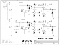
For my own use, I created an "almost cloned" version of Nelson Pass's PCB layout for the ACA Mini power amp. Compare my layout to Nelson's, you'll see I did not make an exact copy
But, overall, my board is similar enough to Nelson's that I'd call it an Almost Clone.
I ordered a bunch of these boards from a PCB fab, and don't expect to use all of them myself. So I'll be giving away my extra board for free -- I'll even pay the shipping. However I'll only give them to diyAudio members that meet a couple requirements:
So, if that's you, send me a Private Message, and address each of the four requirements above. I'll wait a week or two, collecting the PMs, (since plenty of members only look at diyAudio once a week), and send out my replies. I expect to get PCBs back from the fab some time around 17th Dec or so.
ANSWERS TO FREQUENTLY ASKED QUESTIONS
Will I give away my Gerber files? No. The ACA Mini will eventually be sold in the diyAudio Store and you can buy it there. This board is only a stop-gap, temporary measure, while everyone waits for the official Store product(s).
Am I willing to ignore the four requirements above, just for you, and sell/give you a board anyway? No.
Do I know anything about the schedules, prices, or future plans of the diyAudio Store? No.
(... room for further expansion as new inquiries arrive ...)
_
- Mine uses 45-degree angles; Nelson always avoids these
- Mine rotates the big capacitors by 45 degrees. Why? Because I can.
- Mine has a much wider ground buss on the bottom copper layer
- Mine includes a "stack" of 5 resistor bodies; Nelson's "stack" is only 4 resistors
I ordered a bunch of these boards from a PCB fab, and don't expect to use all of them myself. So I'll be giving away my extra board for free -- I'll even pay the shipping. However I'll only give them to diyAudio members that meet a couple requirements:
- Ship-to address needs to be inside United States // no international shipping
- Recipient needs to recognize: this is an untried prototype PCB, and may have issues (even despite passing Layout-vs-Schematic verification software)
- Recipient needs to have already ordered the high value parts (JFETs, MOSFETs, heat sinks, snap-in electrolytic caps). Be ready to email a photo.
- Recipient needs to have plans to complete the ACA Mini Almost Clone before 15 January 2022 -- and must be able to convince me they're an enthusiastic builder, not a mere hoarder of blank boards
So, if that's you, send me a Private Message, and address each of the four requirements above. I'll wait a week or two, collecting the PMs, (since plenty of members only look at diyAudio once a week), and send out my replies. I expect to get PCBs back from the fab some time around 17th Dec or so.
ANSWERS TO FREQUENTLY ASKED QUESTIONS
Will I give away my Gerber files? No. The ACA Mini will eventually be sold in the diyAudio Store and you can buy it there. This board is only a stop-gap, temporary measure, while everyone waits for the official Store product(s).
Am I willing to ignore the four requirements above, just for you, and sell/give you a board anyway? No.
Do I know anything about the schedules, prices, or future plans of the diyAudio Store? No.
(... room for further expansion as new inquiries arrive ...)
_
Attachments

Thanks for doing this Mark. Looking forward to seeing more ACA Mini build!
Looks like a cool schematic. But I have a question. Would the 'pre-bias' be needed if a bi-polar supply were used? Does it just get the input up to half of Vcc or does it actually bias the FETs as needed for operation at all apart from serving the needs of the single ended supply design? I'm kind of ignorant on that. Some guidance in this area would be most appreciated. Thanks!
Last edited:
Yes, I swapped the positions of R4 and C5 in Nelson's original layout, which created a fearsome "stack" of five resistors: R4-R2-R3-R5-R6. Try not to tremble at its awesome grandeur.
I also fixed a Layout-Versus-Schematics failure by swapping the positions of R1 and C1. Double check Nelson's schematic against his layout, they don't quite match in the vicinity of the RCA input circuitry. LVS found another mismatch between the NP originals, which I will omit mentioning here; instead I'll leave it as a pleasant little brainteaser of precise and painstaking minutiae. Multi gigahertz computers discover it immediately.
_
Attachments
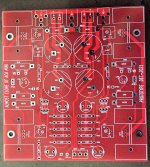
PCBs arrived from fab last night. Did a test-fit of parts into footprints and it all seemed to match.
I'll give members another weekend to stumble across this thread and then send me a Private Message / "Conversation" with answers to the four questions in post #1. I'll decide who gets the very limited supply of boards, send out messages, and start shipping.
_
I'll give members another weekend to stumble across this thread and then send me a Private Message / "Conversation" with answers to the four questions in post #1. I'll decide who gets the very limited supply of boards, send out messages, and start shipping.
_
Attachments
I started down the path of building a digikey cart, and I think the third resistor had a minimum qty of 500. I stopped then. I don't order a lot from digi and mouser, so I might have just missed something.
is there a digi or mouser project BOM that anyone has ready?
is there a digi or mouser project BOM that anyone has ready?
I was using the BOM there, and that's where I hit the wall! I don't need 500 of PPC3W.75CT-NDIt’s already in the ACA mini manual.
Plus, whoever made that PDF made that BOM an image, so you can't select from it. Damn tech neophytes! 🙂
My question was is there a saved project that already has the BOM ready to go? If you are unaware, digikey and mouser let you save projects that you can share with others so everyone doesn't have to reenter the entire BOM.
These R8,R9 are not critical sound wise. I found the following written in the manual;
¨Because the transistors will drift with temperature, we add resistors R8 and R9 to the Source pins of the output stage Mosfets. Known as degenerating resistors, they make the two devices more matched and provide ballast to stabilize the bias current.¨
I would just buy another brand, just stick to the same value, power rating a make sure it’s physically about the same size.
Ps I’ve never used people’s BOM ready made for Digikey since I have fun selecting every component.
Eric
Hi everyone,
Tuesday 21 Dec at 1:00AM San Francisco time is the deadline for sending me a PM containing answers to the four questions set out in post #1. Then I'll choose the recipients and start mailing out PCBs.
Tuesday 21 Dec at 1:00AM San Francisco time is the deadline for sending me a PM containing answers to the four questions set out in post #1. Then I'll choose the recipients and start mailing out PCBs.
Thanks everyone. Recipients chosen, PCBs shipped, now awaiting builder's comments and listening evaluations.
Hi Mark,
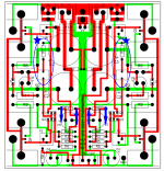
I took a look on your layout and have some suggestions to make it maybe a little bit neater (pink "routes"). Also I've found some unsymmetrical routing left vs. right (marked with circles).
some questions/remarks:
thx for your great steady support for the community! I use your quasimodo for every build btw.
I took a look on your layout and have some suggestions to make it maybe a little bit neater (pink "routes"). Also I've found some unsymmetrical routing left vs. right (marked with circles).
some questions/remarks:
- from the schematic I see no reason for the second smaller routing from RR/RL9 to GND - did I miss something?
- do the plated holes on the bottom have at least 8mm (for 3mm holes) spacing to the trace beneath? if so why the left is routed different to the right?
- it is not so proper practice to route on the top layer under those type of heatsinks. therefore good packages shows a top restrict/keepout. but I know it is difficult without it.
- does these bigger resistors get hot? if so a cutout or some holes under the body could be a good idea.
thx for your great steady support for the community! I use your quasimodo for every build btw.
Attachments

I received one of the Rev A boards from Kevin Heem's group buy along with the unobtainium actives and am building it up. One interesting point of note is that Mark's clone board implements the modification recommended by Papa in post #111 of the parent thread:
Since my JFETs have an Idss of 7.5mA, this is perfect for me. Thank you Mark for being so thoughtful with this clone.
>If you use more than 7 ma I recommend bridging the wiper and cw pins on the pot to keep the Vds of the jfets at an adequate voltage. The idss limit on the jfets would be that of dissipation, but there is little advantage to the higher values.<<
Since my JFETs have an Idss of 7.5mA, this is perfect for me. Thank you Mark for being so thoughtful with this clone.
ACA mini is a fantastic little amp. Looking forward to hearing your impressions of it!

As you wish, my fren!ACA mini is a fantastic little amp. Looking forward to hearing your impressions of it!
Impressions from the test bench
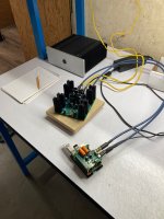
Received my Almost Clone board yesterday & soldered up everything except the MOSFETs and their heatsinks in the afternoon. Today I followed 6L6's build guide specifically for the MOSFET ***'y step (thank you!), adding a touch of solder paste to the heat sink pins to help with forming solder beads, which never really did spread- it left little mushroom caps on the pins which seemed to keep the heatsinks in place well enough. Cleaned off the solder residue with acetone on the patio & powered it on back in the garage with open inputs & outputs using my ACA's 24V Meanwell brick. To set bias I fiddled at first with two voltmeters, each with clippy leads but ultimately went to a single voltmeter with probes held by one hand, the other hand turning the pots. Mark's test point layout makes it very simple- you hold the red probe on TPL1 and bounce the black probe back and forth between TPL2 and TPL3 to read VB and V0, respectively. It wasn't too hard to dial in 0.15V and 11.5V on both channels, so I left it on over lunch and dialed it up to 0.30V VB when I came back. Left channel V0 was 11.67V, right was 11.71V. Decided it was time for music, so I powered it off and hooked it up to the Klipsch bookshelves I use on my test bench.
I played some Bandcamp music off my phone through a Bluetooth adapter and immediately noticed a difference in bass control and volume as well as overall clarity and detail compared to the ACA. The amp was easy to listen to loud and I kept cranking the volume up. I pulled the jumpers briefly but thought the bass got muddier so I put them back in and left them there. I then tried a different source, a Raspberry PI with a fancy DAC soundcard on it. The midbass 'diction' on songs like Paul Simon's Mother and Child Reunion and Joni Mitchell's Hejira was striking. If anything, there seems to be less color to the midrange than the ACA has but that could be a leveling thing.
The amp's heat sinks got hotter during the RPi session, 52-53C, and I kept checking and backing off the VB to 0.30V on both sides, with final V0 of 11.63V left, 11.58V right. I'm going to mount this thing on a wood plinth & try it on my same system. I'm building a pair of Fostex full-range speakers in back-loaded horn enclosures and I think this amp will be a lot of fun with those.
Much thanks and gratitude to KevinHeem for running the group buy and his unexpected gift, to Mark Johnson for designing and sharing this thoughtful clone PCB, and of course to Nelson Pass for creating this amazing little thing in the first place for us all, and generously providing the essential FET unobtainium that make it a reality!
Attachments

I see you also have an ACA. Can you add any more to your impressions of differences between ACA and ACA mini? What do you like about one vs the other and why? Or what is the same? Thanks in advance for your comments..........
Much thanks and gratitude to KevinHeem for running the group buy and his unexpected gift, to Mark Johnson for designing and sharing this thoughtful clone PCB, and of course to Nelson Pass for creating this amazing little thing in the first place for us all, and generously providing the essential FET unobtainium that make it a reality!