3-way Kharma clone

After selling my beloved Martin Logan Sequel II I'm playing with the idea to build a set of loudspeakers with the Veyron 4D design as a starting point:

Concept 3.JPG

Concept 5.JPG

Concept 4.JPG


Not sure about the drivers.

First idea for the drivers:
1x SBA Satori TW29BNWG
1x SBA Satori MW19P
2x 11" Woofer ?

What would be a good choice of drivers? I would like to try a berylium tweeter but also read some good stuff about those Textreme woofer/tweeters.

LM1875 Amp layout

Hi Peeps

I have been gathering parts for a stereo amp build and am at the construction stage. This is my second diy amp, using two LM1875 boards.

I wanted a compact unit to go with my DIY bookshelf speakers.

Can I get some advice on component layout, what do I need, what don’t I need, can it all be squeezed in?

Here is a picture of the parts in the case.
Components:
Toroidal 120VA
DC power supply board
2 x LM1875 amplifier boards
Preamp board for iPhone (if needed) and separate transformer (blue)
Speaker protection board (not yet assembled) and separate AC transformer (blue)
Anodized aluminium case with side heat sinks from Ali-express
Copper sheet to make a shielding can for the transformer if needed

It is very tight with all components used and I am not sure how to best arrange it.

Thanks

Attachments

  • 9E8F080F-65D1-47A8-9EAE-975F878B1252.jpeg
    9E8F080F-65D1-47A8-9EAE-975F878B1252.jpeg
    871.6 KB · Views: 2,464

For Sale Many electronics

I have discussed with my father what he'd like to be done with his electronics. We are selling them. I have decided to add all of my electronics to the mix, because we could use the money, and I'd like to fund some projects too.

Wyred 4 Sound ST-500 MK II $800 plus shipping
Topping DX7 Pro $450 plus shipping
Harman Kardon HK 775 monoblocks. Full restored. New cables, new caps, bunch of stuff. One of them is missing a power on switch, and some screws are missing which would be easy to replace. $500 plus shipping
Quad Vena. The remote is broken but you can buy replacements for like 20 bucks I think. $325 plus shipping
Onix OA20/2 it works perfectly, but then sometimes starts to buzz? $150 plus shipping


There is more, but I am working from memory here and this is what I can think of right now. Open to offers!

Line array alternative

I have 24 Dayton DMA58-8 drivers (2” fullrange). I was going to use them in a line array but the aesthetics no longer works for my listening room. What suggestions would you recommend for these drivers? I’ve considered a Tekton Inspired design and also something similar to an Opalum on wall design. These will be a free standing tower and I would add a woofer or two for the lower octaves. I don’t need to use them all but would like to use as many as I can. This will be a passive design using a two channel amplifier.

any suggestions?

TL494 Class D amplifier

Hello to forum. I have few weeks try to make a classD amp using tl494 PWM chip.
i'm try booth schematics
tl494 class d.jpg
klas D gdt.JPG
and i think is waste of time. First schematic i think they have problem to phase split stage and second schematic is never work.
when i run the circuit about 40vDC everythink works fine but if i increase voltage about 80/100vDC, amp works for 5-10 minutes and output fets are blown up.
i Cant find a formula to calculate the output inductor (LC filter), informations about inductors arround internet, forums etc are incorrect and i'm searching a simple schematic using single TL494 with descrete parts or TL494 with hi low driver such IR2110 or something.

I have spice model for TL494 on multisim but i cant find a schematic to test it.

Thanks a lot.

FS: Mirand Audio USB DAC V.1 AK4490 DSD direct diy

MIRAND AUDIO DAC VERS 1. AK4490 V1

many pmlcaps smd in dac and shield pcbs. (Polymer Multi Layer Capacitor)
n. 2 transformers, 1, RCORE 30 W & EI transformer for XMOS separate supply
n. 4 separate supplies for Xmos , Dac, Clock, with ultra lownoise LDO regulators, 2 x LT3045 ( Ivanov) , 1 KoSa (LT3042 with pmlcaps ) 2 x Mvralica, one for Raw another for Xmos
all snubberized with Quasimodo.
Modified Ground path.
New Ultra precision Crystal Clock NDK SDA ( the original quartz were " normal")
Please note n. 8 Mundorf Mlytic 10kuF 25 V

Dac SOUNDS DSD Direct (Original PCB can't) with Arduino soldered near Xmos ( see pictures) Arduino is programmed for modifies Xmos firmware. (see picture n. 6)

nextgen rca Output wired with UPOCC 24 awg

All AC and DC wire are Neotech UPOCC 18 awg copper wire

Dac Sounds GREAT and it's done as follow: SEE PICTURES

Price € 450 plus shipping

MIRAND V 4.jpg
MIRAND V 5.jpg
MIRAND V 6.jpg
MIRAND V 7.jpg
MIRAND V 8.jpg


MIRAND V 1.jpg
MIRAND V 2.jpg

Attachments

  • MIRAND V 3.jpg
    MIRAND V 3.jpg
    96.1 KB · Views: 155

NFB in circlotron. More NFB = higher THD. Why?

Good morning,

Yesterday I assembled this OTL circlotron. The tubes are 17KV6 (beam power tube) biased at about 100mA (circa -25V at their grids), the lower FETS are IXTP08N100D2 (depletion, 1000V), the top fets are STF3NK80Z (enhancement, 800V). The input transformer is a LL1540, wired for 1:1. Even though all power supplies are 180V, they are all independent (one for the driver stage, two floating for the output stage).

To test the distortion performance with my SE interface I used a 10k:600R (big) interstage transformer, with the primary wired across the 56R load resistor, and one side of the secondary grounded, other side to audio interface.

First try was without the FB resistors. The gain was about 100x, and the THD (measured with ARTA) was 1.3% @ ~2W (actually 9V RMS in the 56 ohm load). Output at about 10% THD was circa 20W. I found these results quite encouraging.

Then I applied feedback, cross-coupled because of the phase, with 2x 30k resistors. The gain decreased, confirming negative feedback, less noise (less modulation with the 1kHz fundamental), but the bad part, THD increased! I tested lower values of FB resistors, the gain decreased further (I went as low as 10x gain), but the distortion kept increasing. With most NFB I measured about 3% THD at about 1W output power.

How can that be: NFB increasing the THD?

Tinkering about it this morning: the drivers need to provide more gain to be able to apply the feedback. Maybe the distortion comes from there? I have not measured the distortion from this specific driver stage, but a previous driver stage with a gyrator loaded 1000V depletion unit powered with 400V DC gave 80VRMS at 1%THD (and a gain of about 2600x).

Departing from the 2W@1.3% THD without feedback I do think this amp has potential for good performance, so I will insist in this a bit more, and I am thankful for your comments in how to achieve this better performance.

Attachments

  • 2022-08-26 08.56.44.jpg
    2022-08-26 08.56.44.jpg
    244.3 KB · Views: 204

what if these systems actually existed?---Amps and speakers built by A.I.

I don't know if anyone will find this interesting and feel free to remove from the forum if this is overly ridiculous but...in case you are not following current trends in images generated by so called "artificial intelligence," allow me to introduce you to something incredibly trippy, kind of stupid and maybe vaguely inspirational?
I have used what is called Dall-E to generate images in response to fairly simple prompts. How it does what it does is way beyond me but with the right prompts you get some really intriguing results.
The images below are entirely invented by the a.i. If you find this disturbing, join the club. At the same time, I can't help but think this might move how I think about the aesthetics of electronics in new directions. Mostly towards ridiculous maximalist designs with way too many knobs on an amp or drivers in a speaker cabinet.
Haven't yet asked the a.i. to actually try to make something that sounds good.

Attachments

  • DALL·E 2022-09-04 21.50.08 - full view of a large vintage tube amplifier with multiple tubes a...png
    DALL·E 2022-09-04 21.50.08 - full view of a large vintage tube amplifier with multiple tubes a...png
    513 KB · Views: 159
  • DALL·E 2022-09-04 21.46.33 - full view of a large, single cabinet, vintage stereo speaker with...png
    DALL·E 2022-09-04 21.46.33 - full view of a large, single cabinet, vintage stereo speaker with...png
    520 KB · Views: 165
  • DALL·E 2022-09-04 21.49.41 - full view of a large vintage tube amplifier with multiple tubes a...png
    DALL·E 2022-09-04 21.49.41 - full view of a large vintage tube amplifier with multiple tubes a...png
    531.6 KB · Views: 154
  • DALL·E 2022-09-04 21.50.17 - full view of a large vintage tube amplifier with multiple tubes a...png
    DALL·E 2022-09-04 21.50.17 - full view of a large vintage tube amplifier with multiple tubes a...png
    548 KB · Views: 167
  • DALL·E 2022-09-04 21.50.53 - full view of a large vintage tube amplifier with multiple tubes a...png
    DALL·E 2022-09-04 21.50.53 - full view of a large vintage tube amplifier with multiple tubes a...png
    550 KB · Views: 156
  • DALL·E 2022-09-04 21.43.54 - full view of a large, single cabinet, vintage stereo speaker with...png
    DALL·E 2022-09-04 21.43.54 - full view of a large, single cabinet, vintage stereo speaker with...png
    611 KB · Views: 164

Technics SL-7 Latch Repair and Refurbish

I just bought my first record player, a Technics SL-7 with some problems on ebay with the intent to fix it up and use it. It has the infamous cracked latch and is missing the 45 adapter for some odd reason. For those not in the know the lid is spring loaded and two small latches molded into the acrylic lid hole it in place. Without them it won't be able to function, and they are fragile. Otherwise it's a really impressive machine, I'm surprised how much of it is metal.

I'll be honest, when I first bid on it I didn't quite understand how significant the broken latch was, I thought it was just minor cosmetic damage. However I have plenty of machine tools and think I can fix it!

Photo of the machine in question:

IQVUJM7.png


Photo of the infamous damage:

ruPuUI5.jpg


My plan is to cut out the damaged area to get a nice flat area to glue in a replacement latch I machine. We'll see how well this theory holds up.... Thankfully I still have one good latch to measure. I think the machine has been messed with by a previous owner so I want to verify that the mechanism works first.

The reason I suspect this is the 45 adapter is missing and the lock washer holding the platter down is very off center. Not the quality I would expect from the factory.

IHKaDWV.jpg


The edges of the rubber mat are also picked at in some places. I'll have to try to get it to lie flat, it looks like I can just push the edge back into a grove. Some one obviously tried to get into this turn table previously. Hopefully they didn't mess any of it up.

When I power it on the tone arm is stuck and the platter does not rotate. First things first I need to try to free up the arm and I suspect the stuck arm is why the platter isn't rotating. At least I hope so.

Since the previous owner had the platter off I'm going to take a look at whats under it.

r89ecOp.jpg


Well hot dam that's one sexy brushless motor. A PCB brushless motor is not what I expected to see in a device from 1981. Now I'm curious how the magnets are arraigned on the platter.

69SPiIn.jpg


Assuming each ridge is a pole I've never seen a magnet with that many poles. I'm going to have to get magnetic viewing film and see what it looks like. Maybe put an oscilloscope on the main winding too just for the heck of it. My EE senses are tingling, I must know more!

Well that was fun but the next real step it to tack off the dust cover and free up the tone arm. I think I have the right types of grease. I'll post an update once I really get into the machine and start freeing it up. I want to verify that the mechanism works before I put in any effort to fix the latch.


Edit: Are the images way too large for any one? There were ginormous briefly but were fixed when I refreshed.

Came across a bunch of tubes, what should i look at building?

Hi, new to the forum and all that 🙂 Recently i came across about 150 old tubes of various types, ECC81/82/83/88, EL34, EL84, EF804(basically a really nice EL86 i think?), 6/12AU6, some big 6G6 ones iirc? and various other tubes.

So far ive built a simple mixed amp with an ECC82 on first breadboard and just yesterday got it working on perfboard(turns out the headphone jacks i can get locally are entirely useless...). Honestly, it sound like total garbage but there is something very satisfying with listening to something you put together yourself haha 😀

So im looking both for tips on improving the amp i just finished(probably needs at least a lower impedance ground and twisted+shielded wires to the jacks?) and mostly for what i should build next.

The main thing thats been keeping me from building anything more advanced is the need for output transformers. I can get a few hundred VDC fairly easy but impedance matching transformers is not something ive got readably accessible.

Mostly interested in headphone amps atm as i dont have any speakers in my apartment but a nice looking tube amp could be fun to have at the campus lab 😀

TL;DR
I have a bunch of tubes, so many that im kind of lost as to what to build with them.
Getting nice output transformers is probably kind of hard and way too expensive for my student budget.
Getting fairly clean power at whatever voltages needed should not be much of an issue.
Also what are some basic improvements to make to the amp ive just built?

I am fairly experienced building electronics, drawing schematics, making PCBs and so on but havent done much with audio/amps/tubes besides reading.

Power Supply question - RaspPi + MiniDSP

I'm having a noise issue with my setup.

RaspberryPi->HifiBerry DAC+DSP->unbalanced->MiniDSP2x4 balanced->balanced->Icepower 200AS2(x2). I'm using the hanger bus off the 200AS2 to power the Raspberry Pi and the MiniDSP off the hanger bus. DC voltage is converted via a dual output step down DC/DC Converter -
PQF20W-Q48-D512-D. However, when powered this way, there is a lot of digital switching noise making it through to the 200AS2. If I power the MiniDSP from a separate power supply, the switching doesn't make it through... Seems odd as the two outputs from the DC/DC Converter are supposed to be isolated.

Any ideas before I end up double up on power supplies, rending the current dual output useless?

Side note: if I bypass the MiniDSP and run balanced into the 200AS2 and ground the inverting to shield, I get a high pitched noise out of the speaker (~500 + harmonics up to 3kHz - very odd).

Building a bass guitar cabinet: questions

Hi folks, I've been a long time visitor and lurker to the forum, I might have already posted something in the past (I can't remember; actually, I did). Anyway, I'm considering the idea of building a sealed bass guitar cabinet based around this speaker:

http://www.loudspeakerdatabase.com/LaVoce/FBASS15-20

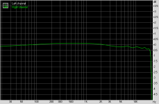
which looks almost perfect for what I want to achieve. It has relatively high Qts and Qes, very good sensibility and a relatively flat, shelf-like midrange rise over 1kHz, up to around 4kHz, which means that it will be bright enough to be used standalone and then some (narrow polar dispersion notwithstanding), without being overly characterised like many woofers with a midrange rise (which show some wild resonance, sometimes 6-8dB in a 1/2oct range or less). It likes large sealed cabinets but it should still work fine at around 70l and some heavy internal padding for bass guitar, since it would have a bit of a midbass hump, less speaker excursion and less low-end extension which is really fine for bass guitar, since I don't really use 5-string basses and most energy is at the 2nd harmonic anyway.

I need 200W RMS max (my amp should be rated at about 180W RMS @ 8 ohm, with some saturation it can get higher but I don't plan to use my amp at full on distortion anyway, you almost never do with bass), a sealed cab because the idea is to use it for studio and small club purposes, and a sealed cab tends to have better transients (which may be irrelevant on bass guitar) and a bit easier to deal with in bad rooms acoustically (which may be much more relevant), and also high output impedance amps are better matched with sealed cabinets, and I might be getting one in the near future. Also, a sealed cab is relatively easier to build.

Questions:

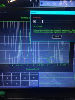
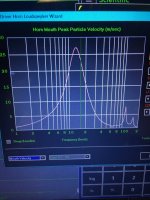
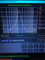
- apparently speakers should never be placed smack centre on the baffle, but they should ideally be placed off-centre. Is this true? Some speaker simulators (for example, the one on Loudspeaker Database) actually show some weird notches when you place speakers off-centre rather than right smack in the middle, which looks weird to me.

- I was thinking of using screws to glue the panels together (which glue?), since I won't be using many wood clamps. Apparently using screws is a bit frowned upon, why?

- also, I was thinking of glueing some wooden rods along the internal edges, where the panels meet, to reinforce the junction (I've seen pictures of this done), and probably a single brace, a "stick" going front to back, assuming that I actually manage to cut the brace well enough so that it makes a bit of a front-to-back pressure. Apparently, bracing full-range cabinets too much makes resonances worse, since you are increasing the resonant frequency into a frequency range where the speaker still emits a lot of energy, while our ears are also more sensitive. What would you suggest?

- what kind of acoustic absorption should I use? I want to avoid using mineral wool since it's an irritant and if there are safer alternatives that don't cost an arm and a leg I'd be happy to explore them.

- finally, sealed cabinets should be well sealed to function well. I was thinking of using caulk along all the edges, while the speaker jack will be put into one of those plastic boxes electricians use for wiring, which would be then insulated against the back panel. That still leaves the speaker: should I use a gasket? There are some bitumen products that apparently are applied along the baffle where the speaker will be mounted. Is it worth the trouble?

Thanks for you advice, and sorry if my questions seem naive, but I'm really a beginner at cabinet making. Many of my concerns might seem overkill but since I would like to make a studio-worthy cabinet as well as a relatively small (smaller than my 2x12" cabinet for sure) cabinet for small gigs, I'd like it not to have issues that would prevent it from being useful in such a situation.

Using label printer for documentation purposes

I normally use a notebook to document my design work, with scribbled drawings between the text.
To improve those illustrations I experimented with screen captures printed with a label printer (I have a Brother QL-800).
The problem is that line drawings or graphs do not come out well, the lines are very thin and missing pixels.
IF it would work well it would be a great time saver and improvement in documentation.

Does anyone have experience printing this sort of stuff on a (thermal transfer) printer?
I looked at A6 size printers but they all seem to be photo printers; even if I could get them to print external .pgn and .jpg files,
the prices for photo paper and the ink cartridges would make it too expensive for regular use.

Any other ideas?

Jan

Servo PCB for L1210/65 (CDM12.1/VAM1202) from Daisy -where in use by Marantz (Schema)

I need a schematic for the Servo/Decoder PCB, which is in use in the loader L1210/65 from Daisylaser (for mechanism CDM12.1, VAM1201 and VAM1202) - go to
pictures
Daisy call this PCB as follow:
"New CD7 II (SAA7327) servo-decoder for improved playability and reliability"

I read follow numberings on the PCB from Daisy (have a look to the PDF images):
1) HECD-019A
2) DN24A533

about
http://www.homecinema-fr.com/forum/viewtopic.php?f=1057&t=29731403&start=345
there are additional informations, mostly unfortunately in french language.
about
http://www.jacquesstompboxes.com/oscillo.htm
are to find the predecessor of this servo boards at a CD722 from Philips (scroll down).

There was produced several top class cd player in very small amount, where this PCB is in use. AVI (lab Series), RESTEK (Mini Pla), Northstar and various models from Micromega are examples.
Here some links of such brands:
http://home.arcor.de/dauner765/minipla/index.html
SoundStage! Equipment Review - North Star Design Sapphire CD Player (2/2008)
Audiophile Corner - CD Integrated Players
http://www.6moons.com/audioreviews/stello/hero_cdopen.jpg
http://www.audiozakupy.pl/_gfx/products/p_cd2vr_01.big.logo.jpg
http://www.diyaudio.com/forums/digital-source/156764-philips-vam-1210-a-2.html
pictures

Unfortunately this PCB isn't in use in Philips/Marantz CD Players like CD710, CD722, CD63 or CD67. Thus the service manuals are not helpful.

Who knows brands, which have produced cd player in large amount where this servo board is inside (like Marantz) ??

Such brands must actually publish the schematics (in opposite to DaisyLaser).

Thank you very much for advices

Attachments

split rail terminology

Newbie looking to clarify input voltage terminology for power amps.

I'm trying to replace the TDA8920BTH power amp module in my VX-11 subwoofer. The remaining electronics are fully operational, and it looks like the power supply is ±25.8VDC. When I search "class D amplifier board" I see the following examples:

"Operating voltage: DC± 15V- ± 27V (recommended voltage: ± 20V- ± 25V)" or "DC dual power"
- this is what I have from the subwoofer power supply
"Input voltage: AC dual 24V voltage power supply is recommended", "Input voltage: Recommended AC dual 24V (up to 30V)"
- is this power directly off the transformer? e.g. 2 24VAC voltages 180deg out of phase?

and also,

"Working voltage: DC24-42V switching power supply (DC)"
- is this just single-rail DC power?

Do I have it right?


vx11 class D.jpg

An Amazing Joinery Machine with Great Potential for Loudspeaker Cabinets

I am decidedly in the "Enthusiastic Amateur" category as far as woodworking goes. The lovely cabinet making in my photos is by Corwin Butterworth. I do enjoy going to "professional" events such as the Journal of Light Construction "Tool Show." It was there that I encountered the Lamello Zeta P2 Tenso system.

This amazing machine cuts an arc-shaped slot in the work piece that is wider at the bottom. How it accomplishes that has to be seen to be believed.

Login to view embedded media
There are several varieties of high-tech "biscuits" that fit securely into those slots. Securely, because the slot is wider at the bottom, and so are the biscuits. The biscuit relevant to loudspeaker cabinets is the "Tenso," which has self-tensioning "claws" that exert 30 pounds of pull once the two facing pieces have been pushed together and the two parts of the Tenso snap together.

Bottom line: You can glue and snap together a flat pack, and there is no need for clamps, because the biscuits are self-tensioning.

However, for it to be worth USD$2500 to you, you have to have an operation that makes lots of cabinets. Or, you are a somewhat self-indulgent (mea culpa, but I have not yet bought one) amateur. I did see several demos at the Tool Show, and I did heft it, but they did not want people who walked in off the street playing with their power tools.

The original intention was to speed the installation of custom kitchen cabinets, but it seems to me that the usefulness for loudspeaker building is obvious.

ciao,

john

Attachments

  • csm_1_Zeta_Anwendung_1a039a678e.jpg
    csm_1_Zeta_Anwendung_1a039a678e.jpg
    23.9 KB · Views: 156

Bypassing / Jumping Pots? Ex: Rotel RB-1050 or Parasound HCA-1000a

Hi Gents,

I posted this on another forum, my first post here - this board has been an amazing source of knowledge, wisdom, and experience for me in the past, I finally registered here.

what is the general consensus on removing pots from the signal path? Looking at an RB-1050, there are two pots for each channel at the front, introduces wire, probably signal quality loss, and would do nothing for me.

Conversely, when looking at Parasound's HCA-1000a, there are 'THX Level' pots at the back, throttling the input..

In either of these cases, what might the procedure be to remove these pots from the chain, simply jumper?

In the case of the Rotel, I found the schematic here:

https://www.manualslib.com/manual/708557/Rotel-Rb-1050.html

Parasound, I was able to find this photo of the back of the pot/input board:

https://i.redd.it/tnlk2c5qnx851.jpg

Appears to me the Parasound is a significantly better amp, but interested in your thoughts on this too.

charging a modded Pure Evoke 2

Hi all,i brought a pure evoke-2 non working,when i got it the tunning rotary encoder was busted,i renewed that and fitted 3 banks of 2 18650 cells 1500 mah so 3ah total at 12.6v
it runs thru a 3s bms,i have a psu 12v at 2a,will that work,ie does the bms control the charge current or the charger,i know 12v is low as should be 12.6 but thats better for the cells.TIA.

Help needed on Tone control section

Hello all,

I have been working on building a pre amplifier with Ne5532, so I designed it in Multisim and everything worked OK.
After making the board and testing it with Rightmark Measurement software, it worked great until I noticed that when tone pots are positioned at center
every thing is ok and based on the design the mid band (800Hz) will not get affected by changing the pots position (Just like the result in Multisim),
but here the mid band is going to boost/cut between -/+ 4 dB with turning the pots to min or max. I checked the board and it seems to be ok.
I attached the schematic and frequency responses in deferent positions. Any thoughts or comments on this will be appreciated.
Alan.
Schematic.png

Response at center positioned pots:
Spectrum.png


Treble at max:
Spectrum1.png


Bass & Treble at max:
Spectrum2.png

Attachments

  • Spectrum.png
    Spectrum.png
    3.8 KB · Views: 94

NAD-208 overheating Issue

Hi Folks , got a little Stange one for you
I have a NAD-208 on the workbench i have rebuilt the outputs and power supply board due to it overheating and burning out most of the components
so i have repaired the boards and replaced all the bad components and restored it to a working condition
the issue i am having is the output boards in one area of the PCB circuit after running for 5min climb to 75 degrees Celsius which to me seems a little on the too very hot side I have marked in red the area of concern
Note all components in this part pf circuit have been checked and passed ok
Please review below specifications and my actual voltage supply rails at present
My question is this-- What would be causing both of the output modules to be overheating at the same time in the same place other than what i have noted below?
I have updated the high current bleed off resistors on the mosfets to a 5w from a 3w to compensate for excessive current draw
the only thing i have noted that there is VHH128vdc going into the rail through a 150k2w resistor wire wound that is very hot one side of the resistor goes to the voltage driver regulator measures 128vdc one side the other side 25vdc so i would imagine that's 100vdc beleed off in heat from current draw
the resistors measure ok in circuit and ok when removed and tested on the bench
Not sure if this Amp is meant to operate like this as it came in non-operational so i have no reference to go off
Your assistance is much appreciated

Please note the following specifications

NAD=208 SPEC NAD=208 Actual
VHH = +120vdc VHH= +128vdc +8vdc over
VH+ = + 80vdc VH+= +89vdc +9vdc over
VL- = -80vdc VL- = - 89vd _9vdc over
VH- = -120vdc VH- = -128vdc -8vdc over
+18v supply +18v Supply Correct

Attachments

  • nad2081.jpg
    nad2081.jpg
    347.9 KB · Views: 117
  • nad2082.jpg
    nad2082.jpg
    383.8 KB · Views: 107
  • nad2083.jpg
    nad2083.jpg
    422 KB · Views: 114
  • nad2084.jpg
    nad2084.jpg
    402.7 KB · Views: 115
  • nad2085.jpg
    nad2085.jpg
    261.3 KB · Views: 117
  • nad2082 marked.jpg
    nad2082 marked.jpg
    447.8 KB · Views: 113

Specifying capacities of xover components

I've used a few xover calculators, and they cheat. They don't use amplifier power or speaker power handling anywhere in the criteria. For me, that's been the difficult part. I really can't quite determine the voltage ratings of the capacitors, power specs for resistors, and current specs for coils. And, nowhere can I find the subject discussed .

It could be that it's just so simple, like taking a shower or getting dressed, that no on bothers writing an explanation. Or it is more likely quite a difficult subject most people avoid discussing/explaining. So, given a wpc minimum RMS amp rating, what should my xover component capacities be, i.e. voltage, power and current capacities? How are those calculated? I'm sure I'd figure it out eventually, but I want to make 2 xovers right now.

Thanks for all the help.

Testing STK0040-II ICs?

Currently fixing an old JVC JA-S22 amplifier. It came to me with two blown rail fuses and no relay clicking when the power button was pressed.

Lights come on when power button is pressed. On closer inspection I found it contained STK0040-II ICs. Upon replacing the rail fuses, I then powered up the unit and got the following voltages when testing each leg of the ICs:

Pin 1 = -1.2V
P2 = -35V
P3 = -0.02V
P4 = 0V
P5 = 0V
P6 = 0V
P7 = 0V
P8 = -0.01V
P9 = 0V
P0 = 0V

I presume from these readings that both of these ICs are blown (which I think would cause both rail fuses to be blown too) thus causing the amp to be stuck in protection mode.

The service manual doesn't have the voltages from the ICs displayed on the schematic. Does anyone know the sort of voltages you would expect to see on a working IC?

AutoEQ on demand - using ESP32 as TCP/IP channel server

Hi,

I incorporate AutoEq and use ESP32 as TCP/IP channel server for "AutoEQ on demand".

An ADAU1701 outputs white noise via a speaker. A microphone picks up the signal thus the original frequency response of the speaker is known.

To equalize, PEQ coefficients were calculated on demand (on a PC) and sent via WiFi to an ESP32, which in turns modifies ADAU1701's parameter RAM and set the coefficients.

Please see:

1. AutoEQ to flat line

2. AutoEQ to Harman curve

3. Experiment setup and test result

4. Code example

5. Video (please switch on the caption)


Regards.
  • Like
Reactions: Baffless

Lifted pad, what now?

Hi all
I , uhm, I think I have managed to lift a solder-pad by overheating it. Sorry I forgot to take pictures, but, before soldering the part there was that little ring—the pad—looking upwards on the opposite side of the track.

I then cowardly soldered that pad and it looks as if nothing happened.

I shall be optimistic until proven orherwise, what are the methods to fix a such damaged pcb?

Thanks!

Anyone running active crossovers in thier setups?

I just bought a Dbx driverack 260 (it hasnt arrived yet) and im keen to tune the Magnepan 2.7 qrs that i have to the smallish room that i have and want to run the high pass filter at about 60hz and maybe use the eq to tune it to the room a little and was going to run an output to the sub at a 60hz low pass point. I bought an old Carver pm 1.5 to power the maggies and it sounds far better than the class a monoblocks and the 200w adcom 555se I had before it. Its all being controlled by a computer running Jriver media centre through a Nad dac preamp-is anyone else using loudspeaker management systems like this and what is your setup?

Adding single rail amp to split rail amp power supply

I want to add a single rail (class D) power amp to an existing split / double rail power amp module.

The existing amp is a subwoofer module with a 2x24V AC transformer mounted in a subwoofer cabinet. I want to power the 2 satellite speakers from the same cabinet by adding a class D amp powered by the same supply. I am assuming the power supply has sufficient spare capacity.

Typically class D amps use a single voltage rail. How do I feed this amp from the existing transformer?

I can imagine the ground of the split rail and the single rail get mixed up?

Attachments

  • Existing power supply subwoofer.jpg
    Existing power supply subwoofer.jpg
    50.1 KB · Views: 236

Njm2073

I haven't seen it discussed in detail and today I bought for very cheap a s**tload of EJ-770T 860MHz transmitters having these op amps as headphones amplifiers.The rest of the audio op amps are all njm2068.Even though the datasheet of njm2073d didn't look impressive his specs were given for 8 and 4 ohms with a high capability of max 2 watts at 10% thd in 4 ohms!
The final op amp is routed as in stereo mode, but its input is mono which is a shame cause his sound on 250 ohms dt880 pro is really good with all those stock caps and God knows what particular stages and gains topologies before it.
Now what really struck me was that supplied by a cheap 12 wallwart smps ( the 9 and 5 Vregs are only for the digital supply) the output with max volumes and gains is simply inaudible, complete silence.
I'm going to route it in stereo mode with its 9 v reg in series and see the results cause I feel this op amp is an unknown gem.

Attachments

  • 20220904_204144.jpg
    20220904_204144.jpg
    682.6 KB · Views: 145
  • 20220904_204317.jpg
    20220904_204317.jpg
    422.9 KB · Views: 140
  • 20220904_204324.jpg
    20220904_204324.jpg
    461.6 KB · Views: 138
  • 20220904_204356.jpg
    20220904_204356.jpg
    539.4 KB · Views: 145

IRS2092 for HT active speakers

IRS2092 Mono board

Dual 60v power supply 600w

Hi all, I am setting out to assemble an active speaker HT system. I have shortlisted this board and power supply that I have linked above due to price vs claimed performance. I am purchasing 5 of these for full range channels as well as the 500w x 2 amp in the 1kw thread for the active sub duties

I only need around 150wrms in 4 ohms from this board and I would like to run a lower voltage power supply, but the minimum requirement is dual 58v. Would a dual 48v power supply turn this board on, and what power would it likely produce?

I also want to run a tube preamp type stage before the input of this board so that the audio signal coming to the active speaker picks up tube flavour and not sure whether to fit a stereo preamp board with channel one feeding into channel two via a pot or to instead build a mono channel from a tube headphone amp and use the output from the output transformer to feed the class D board input. I am not sure which approach would best for tube flavouring and would appreciate some help with this. I'll start a thread in tubes section about this

Lastly. I would like to flatten the frequency response of each active speaker in its room location and then impose a saved eq curve on them. Can I use DSP for this? Where do I start? I am confused about implementing a single channel DSP. Or do I have no options there and have to build passive speakers and a 5 channel HT power amp and fit a DSP board to that?

Please help with this, I have been saving up for a while for this project and finally purchasing the bigger ticket items. I would like to buy the supporting parts to before the saving are used up elsewhere

Thanks and regards
Randy

Was Nautilus bunk?

I hope this is a fun and informative thread!

I have a serious question. I don't want to debate whether B&W speakers sound good. That's endless and IMHO useless. What I want to talk about is the concept of letting waves dissipate into a tapered transmission line-like enclosure instead of a sealed or ported enclosure.

To put this on a continuum, on one end we have sealed boxes, which have a serious potential to get reverberation from inside the box to come back through the driver. On the other extreme are dipole speakers with true dipole tweeters (without sealed enclosures). There is no cabinet at all.

Somewhere in the middle is the Nautilus camp. I'm not sure if it is original to B&W, but the idea of using a tapered, lossy pathway that absorbs most of the back wave. Focal uses this now in some of it's tweeter designs like the Sopra, but we also find it in other designs as well.

My point to all of this is, has anyone measured that this particular parameter is actually enhanced?

Best,
Erik

SB Acoustics Satori MTM: MW16P-8 + TW29BN-B

Here's Troels' SB MTM D'Appolito speaker build. Instead of floorstanders, these speakers sit atop a stereo pair of subs. Maintaining front baffle width, the height was decreased, and the depth was increased to yield 40L. The cabinet measures 29.5in x 9in x 15in. Instead of 20mm, 25mm Baltic Birch was used on the sides and back, and 38mm black MDF for the front baffle.

Maturity of sound was achieved after 20 hours of break-in. Prior to this construction, I had built the Ellam D'Appos. It was only natural to compare the SBA MTM with the Ellam D'Appo. I was very impressed with the Ellam D'Appos. However, the SBA MTM is a clear uprade from the Ellam D'Appos offering greater transparency, dynamics, image, extension. The 15W mid is an exemplary driver of midrange clarity, smoothness, detail, and potent bass. Surprisingly, the 5.5in Ellam D'Appo delivers as much bass at half the volume of the 6.5in SBA MTM. The price is efficiency, as the Ellam D'Appo is 4dB less efficient than the SBA MTM-16s. Perhaps, the SBA MTM-16's drier bass could also be from its thicker enclosure and more bracing?

Compared to the heavier coned Scan-Speak 18W and 18WU midrwoofers in my other speakers, the light cone weight of the MW16 also produces faster transients and more transparency in the mids. The lack of compression in the mids at high volume is also impressive. The treble is where the SB MTMs higher sensitivity renders inner detail with more clarity, dynamic contrast. The Be tweeter offers more clarity, air, and blacker background than soft- or other metal-domes. The Be tweeter clearly shows more accuity and definition of timbre without smear or veiling of detail in highs. Overall, the soundstage is open, airy, and spacious. Tonality and timbre are well balanced.

The SBA MTM produces a neutral, coherent, detailed, dynamic, open, airy, spacious sound. These speakers are equally suited for analog or digital sources, and solid state or tube gear due to its spectral balance and sonic neutrality. The high efficiency makes them ideal for my KT88 push-pull amp as the difference can be heard.

Attachments

  • 20180701_191304.jpg
    20180701_191304.jpg
    456.8 KB · Views: 2,677
  • 20180702_133335.jpg
    20180702_133335.jpg
    646 KB · Views: 2,268
  • 20180701_020303.jpg
    20180701_020303.jpg
    449.8 KB · Views: 2,214

Elektor "The Complete Preamplifier" articles.

Can anyone help? I started to build this project in 1994 from Elektor magazine articles in the January 1991 and I assume February 1991 issues. Life took over and I put the project on hold. Since then I have mislaid or thrown out the magazines and would like to resurrect the project. Would anyone have the articles? They were written by T. Giffard. Many thanks.

Noisy input on DIY high impedance preamp

I've been working on a project wherein I'm amplifying a very high impedance signal. Typically it will be a piezo pickup, but could also be a ribbon microphone. I decided to use the AMP02 from Analog Electronics, which is expensive but looks pretty good. The problem is, I have an unacceptable level of hum coming from the finished board.
I get pretty good sound coming from the balanced piezo pickup I'm using, but there's a hum that's way too loud to make the circuit useful. It goes away when I turn the volume down, so it's in the input stage. I don't have an oscilloscope to see, but I noticed that of all the places in the circuit, if I put my finger near the input HPF, especially the high value resistors, that the same hum gets much louder. I've triple checked all my grounding wires/cables.
I'm wondering, if the input filter is so sensitive, maybe this is noise coming from my voltage regulators nearby, picked up by the high value resistors?
Is there any way to fix this? I'm willing to try my layout again. This was basically practice at figuring out how to lay out a PCB.

Images:
Schematic
Board Top Layout
Board Bottom Layout

Thanks all! I'm still learning, especially when it comes to this high impedance stuff. I've done chipamps before and of course had no problem, but this is a different beast.

Options? 1” inch Tweeter vs 1” inch to 2 1/2” fullrange Driver’s for top end?

Good evening every. Am was asked to design and make a speaker for coworker and company I work for. So I was looking at the Dayton Audio Reference series drivers RS225P-8 8” inch paper mix driver’s. I haven’t heard them in person but, I have seen the drivers in person.😁. I’m a big fan of textdome tweeters due to not having a sticky coating on the outer dome plus my dads speakers have a seas textdome tweeters. So that being said, Can I use a
use a 1” inch ta 2 1/2” fullrange drivers in replace of a normal tweeter? Am kooking into the small drivers now. I would like some input with this project? The pros and cons? Thanks so much.
  • Like
Reactions: Bryguy

20 mega samples usb scope project.

A while back I designed a 17 mega samples dual channel usb scope.
It works well and sold quite a few.
I recently revisited it and tried to make it faster which I couldnt do using code.
So I had a look at overclocking the PIC micro.
I went from 72MHz to 80MHz and now I can get 20 mega samples.
The bandwidth is 1MHz which fits in with at least 20 samples per cycle.
usb_scope.jpg
  • Like
Reactions: phase

Well done!

Well Done!

Certainly we all quietly think "well done" from time to time, e.g. when we take an audio item apart and are pleased with a clever solution we encounter while doing so. So why not thinking this loudly and publicly, as a counterpart to all these justified critics about misengineered stuff. We all can learn from well-done design.

While working on my Quad63 for instance, I repeatedly had to handle this quite heavy and bulky, but also delicate physical speaker. Taking care neither to damage the Quad63, nor my back. And doing so, I was several times very happy about such a well-done constructive detail, an unshiny, little, hidden but very ergonomic and intuitively "right" feature which came very, very handy:

HandyHandle.jpg

Therefore, many times grabbing, lifting, flipping one of these Quad63, I thought this kind of "well done!" about this simple and useful notch. Last not least: The very best of it consists in the fact, that opposed to many long-term stability flaws the Quads come along with, this feature certainly will maintain it's rock-solid useability over time.

So welcome to share your own "best picks" in terms of maybe less known, but well-done engineering audio gear details and features.

Inexpensive Soldering Station

Last evening my faithful SP-23 Weller soldering iron died after 10+ years of service. I'm looking to buy an inexpensive (my first) soldering station.

Does anyone has this little guy on their workbench?

Yihua 939D+ Digital Soldering Station.

It is supposed to be equivalent to 75W with temperature control 392°F to 896°F. Looks well built. $43 shipped on Amazon.

Would appreciate your feedback.

Thanks
Mayank

Attachments

  • 71CwB2nvGDL._AC_SL1500_.jpg
    71CwB2nvGDL._AC_SL1500_.jpg
    163.2 KB · Views: 790
  • 71ZwGkuHifL._AC_SL1500_.jpg
    71ZwGkuHifL._AC_SL1500_.jpg
    144.4 KB · Views: 754

tapered MLTL vs stepped ‘reduction’ @ 3x 1/4 harmonic node?

Slightly lower tuning with a 2 fold (3 resonator in series) offset driver TL.

used a bigdumb example as it was easy to show a ‘change’ and its being built currently fwiw..

same volume ~850 liters

360 cm x (pi/9) = 125.66 driver entry with 234.34cm remaining (split as 120cm and 114.34cm which seems to compliment a 3:1 CEA reduction (anymore reduction and air speed is a threat @ exit Fb).

(3000cm2)/
x 125.66cm
(3000cm2)
x120cm
for the first 2 folds

then,
(1000cm2) x 114.34cm in the last.

851 liters with 3 dayton audio ultimax 18-22 drivers. Fb @ 14.8hz (electrical impedance null)

vs

tapered as

(3700-2800cm2) x125.66cm
(2800-1900cm2) x120cm
(1900-1000cm2 ) x114.34cm

856liters with 3 dayton ultimax 18-22 drivers. Fb @ 16.0 hz (electrical impedance null)

Attachments

  • image.jpg
    image.jpg
    567.8 KB · Views: 90
  • image.jpg
    image.jpg
    518.2 KB · Views: 92
  • image.jpg
    image.jpg
    646.8 KB · Views: 94
  • image.jpg
    image.jpg
    648 KB · Views: 88
  • image.jpg
    image.jpg
    594.1 KB · Views: 89
  • image.jpg
    image.jpg
    598.5 KB · Views: 86
  • image.jpg
    image.jpg
    522.7 KB · Views: 90

Woofer Storage Position

The few times I have seen woofers stored on shelves at warehouses they have been placed with the wide square footprint of the box on the floor/shelf, never stood edgewise. (If raw, at a shop, usually face down , occasionally face up.)
Yet on some speaker dedicated forums I've run across individual posts or two/three post back and forths on storing drivers vertically (on edge) to avoid spider sag. I'd have thought that long term, you'd just be replacing spider sag with surround deformation.
How much of an issue is this?
Can any problem from long term storage be avoided / managed by occasional flipping over or turning of the box?

Help with 1st order crossover in unusual 2-way design

I want to use 1st order crossover, 2nd order only if its a MUST.

For the tweeter i selected planar GRS PT6816-8 8" open back , which plays down to 400Hz and from there roll-off starts. However, at 400Hz there is about +6dB peak comparing to 500Hz- 3,000 Hz range when it plays at 90dB.
At 300Hz, it outputs 87dB, but at 250Hz only 80dB
From 3,000hz it rises steadily up to 100dB........ Driver is rated at 94dB

My question is, can I cross it to woofer at 1,000 Hz? With first order?
Books say, the driver must play 2 octaves outside of such X-over.

I dont intend to play music very loud or even loud. Room is of avg size for a living room.

By the way, if I match it with 15 inch bass-mid woofer, is it OK with cross @ 1,000Hz? 15inch is rather large.....
But, I've seen speakers with 18inch woofer crossed at 700Hz, so i guess its ok?

Thanks
Any suggestions welcome.

Active 2-way passive radiator nearfield monitor with DA TCP115-4

Hello! Soon I'll be moving out from my house so I need a pair of speakers that I can carry with me. They have to be active because I don't want to carry around an amplifier when I move. It also has to be extremely compact, 4 liters is the absolute maximum but I'd like to stay below that. It won't have to play loud, but I'd like something with a bit of headroom and decent bass extension. It also has to be very cheap.
For this reason, my driver choice for the woofer has fallen onto the Dayton Audio TCP115-4. I want to use the 4 ohm version because it's more efficient.
It goes pretty low in a 2,5liter PR (or BR) enclosure tuned to 60Hz. It's also very cheap.
I think I will use a 5" chinese passive radiator. I will have to measure the tuning afterwards but it should work ok, if it has enough excursion. The SB acoustics models cost more than the woofer!

But I need to find a tweeter. I could either get a new tweeter when I purchase the woofers, which will have to be cheap and of at least 19mm (3/4") in diameter since the TCP can't cross very high, or also a used one. I also want it to have a compact faceplate to keep the two emission centers as close as possible.

After taking a quick glance on Soundimports, it seems that those models are the cheapest.
HiVi T20-8
Dayton TD20F-4
Dayton ND25FA-4 (slightly more expensive)

I don't trust HiVI too much, I've read stories of out of specs drivers, I don't know it true so that's part of the reason why I'm asking.

If I want to get a used one, I could opt out for a pair of Ciare CT190 which cost as much as a pair of T20-8 or a pair of Hertz HT20 (which cost way less). These are also great because they have a metal mesh so they don't get damaged when moving the speakers! Can't find much info about the Hertz, and I'm not too sure about how well the Ciare will tolerate a 3500Hz crossover point. It also has a poly dome and they don't sound nor measure as well as paper cones or silk domes, at least according to my very limited experience.

For the amplifier, I couldn't find anything. The Lepai LP40PA is perfect, however is too expensive given the nature of the speaker. I could just buy an amplifier board and place it inside the speaker, but then cooling would become an issue because the speaker doesn't have a single hole. Do you have any ideas on recommendations on this?

I'm attaching the simulated response (+0,5ohm series resistance)
Schermata del 2022-08-22 15-23-39.png

8" SQ subwoofer design feedback

Hello all,

I'm designing my first subwoofer around a 300 euro budget. It will run in a stereo 2.1 setup for music, in a small room. So my preference would be an f3 just below 30hz, keeping it small, and a focus on SQ rather than SPL.

I landed on the following components, but i'm open for suggestions:
  • sb acoustics sb23mfcl45-4 (I assume the 4Ohm version is preferable) - 140 euro
  • Dayton SPA-100D (or monacor SAM-200D for double the power if necessary, same price) - 145 euro
The maximum box size I am willing to place is 30x30x50cm, which amounts to a volume around 34L.
Setting FS at 29Hz gives me the following TF in WinISD:

1661946918114.png


Adding filters:

1661947020914.png


Now, my question is is it safe to assume that the SPA-100D will HP roll-off around 23Hz? Because if I go below 22Hz we will hit Xmax at 100W. I will probably never use this amount of power, but it would be great to know my design can handle the full output available.

I have read a review of the monacor sam-200D, where the roll-off is desirable. So would I benefit from the 8Ohm version of the driver (Which has slightly worse properties?) and running the 200W amp to get a safe roll-off?

Excursion at 100W:

1661947212058.png


I designed a slot port for the full lenth of the cabinet, which means 2cm x 26,4cm and a lenth of 50cm. 2cm seems oddly small, but I assume it won't be a problem? Port resonance at 350Hz.
Air velocity at 100W:

1661947430498.png


Which is right around the recommended maximum.

So for fun I went to designing in fusion 360. The big cutout is for the plate amp. Is this the correct way to design a slot vent? I will add some bracing later.

1661947557865.png
1661947588728.png
1661947662908.png


As this is my first attempt, all general feedback is welcome. Regardless of the previous questions, would you think it is worth to design this sub for SQ music application instead of buying an entry level 300 euro sub or saving up for something like a rel t5x or svs sb1000? Please keep in mind that i don't have any way to measure and I dont have any way to EQ outside of APO.

Thanks in advance.
  • Like
Reactions: Toaster79

Subwoofer integration

I am think of building a couple of subwoofers for both music and home theater. I am currently running a single 12" powered sealed sub from the sub output of my receiver, crossed at 80 Hz. I also run a dedicated 2 channels power amp to my front speakers which are Magnepan MMGs, which are dipole panel speakers having very detailed sound down to about 100Hz. The sub helps for the very low frequencies, but tends to have the monotone boomy sound, even if I try to adjust the crossover. In other words, it does not integrate with Maggies very well for music.
Rather than building powered subs with a control panel on each, I thought of hooking a mini-dsp 2x4 to the front speakers pre-out and using it as a crossover between the Maggies and the subs. I would have to add 2 channels to my power amp for the subs, which is easy because it is modular and VTV can add a 2x500W hypex module for a very reasonable price. The DSP would also allow me to apply room correction to both sets of speakers. Another advantage is that I could experiment with the sub design without messing with the amps. Of course I would have to build more "musical" subs, thinking of ripoles now. Do you think this would be a sound design? Are there any downsides?

Micro Seiki RY-5500 start/stop button -optical switch repair

My start/stop button does not work and the switch is always is in on -position. It looks like the switch uses red LED (considering the age of the device it can be also a bulb) which does light up because it is likely dead. I can’t see a detector on the panel so I’m not sure how it actually works. I wander if anybody has an experience of repairing the switch or got the circuit diagram.

For Sale Khadas tone board 1

Hello!

I have two khadas toneboard 1 for sale. Got one when was working on my soekris dac chassis to keep music playing. Was very impressed with the quality and sound of that little dac so got the second one. Now when my dam1021 is finished I am rarely using it. Slowly cleaning my gear I don’t use often so these two are for sale. One has maybe like a month of use and the other probably a couple of hours when I was checking that everything is ok upon arrival.
Price is $70/per board shipped in CONUS, PayPal friend or family or please include fees. Thank you for looking!

Attachments

  • 95FB1EA6-7651-4919-BE56-277378115972.jpeg
    95FB1EA6-7651-4919-BE56-277378115972.jpeg
    460.9 KB · Views: 114

2+2+2=1?!

Hi. Newbie poster here so be gentle.
My new project is converting an old (1940s?) wooden radio into a mono, three way, 24v, bluetooth capable speaker for camping etc. but i have run into a modelling issue that I cannot find a previous example of. The bass is being handled by a ported dvc visaton W 130 X driver which will be powered by two separate channels of a 4 channel dsp amp. (zoudio AIO4CH)
My main issue is how to model this in winisd for the port? values are given for the driver according to how the voice coils are wired but there is nothing suggested for this situation where each voice coil has a separate amp channel powering it. my apologies if i have missed this question elsewhere.
Thanks for any advice including why this whole project is misconceived.
NB. no antique radios were harmed in the making of this speaker. It's a 1980s reproduction which didn't work.

For Sale Speaker stands air spring

For sell
Speaker stands.
Couple,
Totally six column
High 38,5 cm without base
The mutual distance between columns is decided by who buys.
They are (if you want) air spring (instruction comes with it but, for information the weight supported is given by spring gasket's thikness )
Come without basement.
You could glue on rocks, , marble, Wood, as you prefer.

Price is € 600 included shipping in EUROPE


photo5766957317277990054.jpg

Aikido a3

I bought a second hand aikido octal kit. The preamp is just finished. In the kit there was an a3 stepped attenuator. There where no instructions but all resistors where in marked bass, so I solder it togheter. When finnished I wanted to check that everything is rigt.
But I only got same Reading (around 100k) when messuring between input and output regardless off switch posisjon.
Shouldent the value change? Not much to do wrong with that pcb.

Zobel network placement

Hi, I'm putting together a TDA2822m amp but I've noticed in the datasheet schematic that the Boucherot cell is placed after the output coupling capacitor as opposed to right at the output pin like many other IC's recommend.

For example this is from the datasheet of the TDA2822m

tda2822m.png

Where as this is from the LM386 datasheet

lm386.png

As you can see the output RC zobel networks are in different places, is the placement on the TDA2822m datasheet a mistake or does it not matter where I place it? I've taken apart a commercial clock radio with a TDA2822m and the zobel network was placed right at the output of the IC before the coupling capacitor.

tl;dr is it better to place the zobel network before or after the output coupling capacitor?

Thanks! 🙂

Dumb question

Just got rid of my home made 8" subwoofer and bought a low cost 12" active subwoofer. So far so good....however

I have it hooked up via spliced speaker cables in parallel to my power amp output that go into the high level input connectors on the subwoofer amp.

In trying to adjust it to a level that blends into my system I'm finding that I have to have the low level cutoff right at the bottom lowest frequency and the total output level turned right down to near zero.

This causes a problem because the pot adjusters are the click type, not continuously smooth, so when I'm almost at the right spot I'm finding one click is too quiet and one click up is too loud.

What I need to do is rescale a little so I'm nearer the mid point and have more adjustment control.

I used a voltmeter on the input resistance on the high level input and its around 650 ohms.

I opened up the subwoofer amp and the level adjuster pot is a 50k unit.

I'm stumped at an easy way to re-scale this thing so the level has more adjustability.....is there an easy way?

Reflection or time alignment?

I'm debating on whether to push the tweeter and mid back to time align with the woofers in my 4-way system. The problem is that I am building this in a cabinet so there will essentially be a shelf very close to the tweeter, I am going to be using felt to soften the baffle diffraction all the way across the baffle, at least that is my plan for now, so I can add felt to the top.

The question is this, is it better to have some damped reflection and no time alignment or is it better to have time alignment and some reflection?
1662244437708.png

Nelson, is this how you wanted the Adcom GFA-555 MKI thermal compensation done?

I hope this is OK to post in Pass Labs... Talking about the old Adcom 555, but it is a Pass design!

I've been selling replacement boards for the GFA-555 for some time now, and I am about to design new versions with some subtle improvements.

I have a question about thermal tracking. I read somewhere you were describing the thermal design of the 555, and what I gathered, was that Q617 and Q619 provide some measure of tracking with temperature... But I wonder if this is one of those cases where the physical layout doesn't match the designer's intentions. Should these transistors be mounted on the output module heatsinks, and not on the input board?? The 555 MK1—as manufactured—actually has quite a pronounced positive thermal coefficient. At idle, each output runs about 50mA, but when hot, this can rise to as much as 150mA, and it takes the amp longer to cool down because of this.

Was the thermistor TH601 in your original design? Maybe it's not even necessary if Q617 and Q619 are mounted to the heatsink?

If this is the case, I can design new output module boards to include these transistors.

Thanks for your consideration, and the excellent designs that I continue to learn new things from.
-Chris


1662236915443.png

KiCad Routing Question

KiCad 6 "Update PCB From Schematic" produces PCB footprints nets, pads .. but no vias to connect them. I only wish to gerber a simple 2-layer PCB and have some confidence that a fab will accept it. Please tell me how I can complete update.

Attachments

  • DRC6.png
    DRC6.png
    4 KB · Views: 123
  • DRC5.png
    DRC5.png
    1 KB · Views: 119
  • DRC4.png
    DRC4.png
    10.3 KB · Views: 135
  • DRC3.png
    DRC3.png
    6.3 KB · Views: 132
  • DRC2.png
    DRC2.png
    7.5 KB · Views: 130
  • DRC1.png
    DRC1.png
    19 KB · Views: 126

Class D amps for 5.1 dual-purpose system

I am actively putting together two systems:
System 1 - 5.1 for our home which serves as home cinema and home studio and used for studio tasks usually about once a week. This is an open plan type home that contains the kitchen and adults bedding in one room. Another same sized room is attached, with an amenities' room separating the two. A full length room run alongside the two main rooms and serves as my workshop, large double sliding doors from main room to workshop. These areas are contained in a square house structure

System 2 - 2.1 mobile box with 3 aux amplifier channels outputs, for a portable setup, which can supply extra amplification on demand with extra speakers. This will be installed in the workshop in a manner that allows easy removal. Mainly for listening to music while I am working, as well as for testing stuff without having to rip into the home system (I hope the logic for common device models is now apparent)

Request
The living room is not a place for a PA system, neither is the sound quality and ability of most of this sized PA systems out there for portable use acceptable. System 1 will be in operation here virtually 24/7. Think of these as being in the same category as the high-end Japanese audiophile disc players that feature mic inputs. I do not believe that anyone would be upset about such a disc player being discussed in a Hi-fi forum, so please may I request that discussion on an amplifier with the same feature doesn't upset anyone's sensibilities
Please regard these as a Hi-fi want to be setup. Both will be used for audio and video reproduction and appreciation and when liquid courage hits the spot, these systems should invite one to grab something and let loose

Desired feature:
  • An ability to keep electronic hardware and speaker driver models common to both systems
  • Emphasis is on quality quite nighttime sound reproduction and ample headroom without loosing composure for other times
  • Switch power supplies (desire to stay away from "ring cows")
  • Tubey audio signature (prefer the sound of the 300b amp for audio)
  • Engineered with the ability to input a live performer or two on demand (In other words, beautiful reproduction of prerecorded material, containing the "studio to mastering" process internally for a seamless jamalong)
  • Low pass channels to be either about; 400 clean watts into 8 ohms - 400 clean watts into 2 ohms - 2 x 200 clean watts into 4 ohms each
  • High pass channels to be about 100 watts clean into 4 ohms

This thread is for the class d amps that will be contained within

I have been saving for this project for a while, and in the meantime pouring over catalogues and specs and pestering folks with uneducated questions and ideas. Time to get to work on these, so I have ordered these items:

Signal IO
This unit will get fitted inside the amplifier case and provide most of the signal IO and act as the brains and system overall volume (has remote) as well as individual channel adjustment
4K@60Hz HDMI 2.0 Audio Extractor Converter DTS AC3 5.1CH Digital Audio Decoder ARC SPDIF Coaxial PC-USB Bluetooth Audio Input

Amplification
To be trailed as the low frequency amp
AIYIMA 500Wx2 Digital Power Amplifier (PSU on the board) x 1

To be trailed as the main channels amp and low frequency amp
HIFI Power IRS2092 500W Mono channel Digital power amplifier x 5
+ Lusya Dual DC 36V Output LLC Soft Switch 500W Switching Power Supply x 1

To be trailed as the main channels amp and bench amp
TDA7492 Amp Class D High-Power Digital Amplifier Board 2x50W (to run in bridge mode as a mono amp) x 1
+ 24V switching power supply board 4A 100W x 1

Speaker drivers
Low frequency
Dayton Audio RSS265HO-44 10" Reference Series HO DVC (delivered) x 1

Main channels
Already have a number of various pairs of bookshelf types on hand. Working on an interesting 6" coaxial speaker alongside this project, I am using some very interesting sounding drivers that I auditioned and bought, but I fear derision on my choice here

Reason to post thread
I am getting some promising looking kit that might help me acquired the desired sound system. Please guys, help me with peer review of my choices and suggestions to gear that I may not have noticed. I know create folks out there will have some great ideas too. Please help with mod suggestions as well as education pointers in anything I may be lacking. This will also be a log for me to help keep track of my project

Thanks and regards
Randy

Large two-way speakers, like Seas A26

I was looking at the Seas A26 kit and was intrigued by its "naked" use of the 10" woofer. I seem to recall that Reference 3A favored the same methodology -- i.e., running a woofer "naked" without a crossover while using a tweeter to fill the top.

My question is whether there is a similar, two-way design using a 10" or 12" woofer for cabinets (sealed or vented) that are much larger, say 85L or 3 cubic feet. The goal here is to hopefully obtain the same level of midrange purity while also getting a bit more bass.

Thanks!
Projects by fanatics, for fanatics
Get answers and advice for everyone wanting to learn the art of audio.
Join the Community
507,730
Members
7,886,115
Messages

Filter

Forum Statistics

Threads
406,133
Messages
7,886,115
Members
507,730
Latest member
plumb stupid