Musical Fidelity, well regarded as Hi-fi, added new equipment back in the days (that technically would contaminate the signal) in an attempt to increase audio listening pleasure. This was a tube stage that connects before amplification, and I think most folks know about this. My type of questions always get called effects devices and ignored or told to be moved to instruments and PA
My system is getting assembled, according to the details further below from my thread in the class D area to discuss the amp boards and power supplies. I need some direction with the tubes, some peer reviews and suggestions would be very highly appreciated
I am about to start ordering some online kits and boards that are tube based. I think I need one setup to provide channel tubyness and I have the desire to have one or two aux channels that have a tube based preamp and tone on them that are switchable to take them out of the circuit
Tubyness
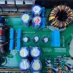
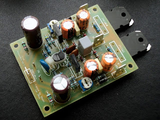
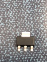
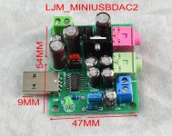
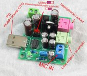
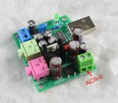
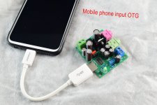
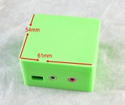
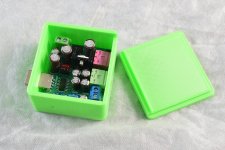
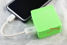
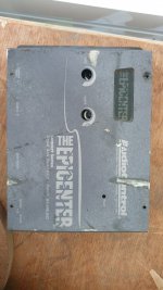
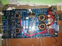
I have selected this device for channel tubyness, may be able to get away with 3 units to flavour my 5.1 channels independently. I won’t be using the .1 output of the decoder, instead the signal will be routed in the decoder to the main L and R speakers. I hope to use the unit flavouring FL and FR as the system headphone output too and the signal out from this lil amp with have a low passed signal for system subwoofer
- Am I heading in the right direction with this board?
- How does it work without output transformers?
- Are there any output transformers that may enhance the task that I am asking of these?
- Are input transformers with this of any merit?
- Is it ok to run the headphone output into the input of the class d boards?
- I would like to run a switching power supply instead of a "ring cow". Is this ok to do with this design? Should I take out the regulator stuff out of this board if I find a switching supply?
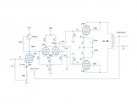
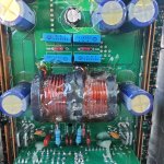
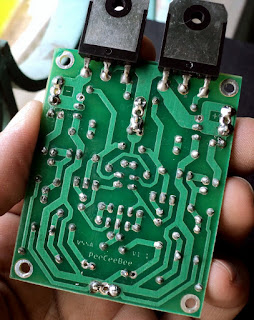
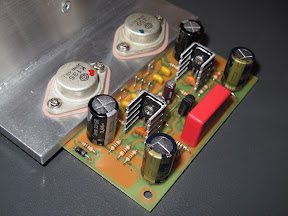
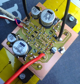
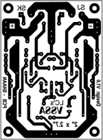
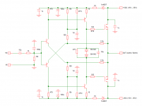
SIngle ended tube triode amplifier for hifi 6N5P 6N5C Headphone amplifier class A (will order 1 after posting this)
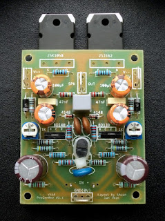
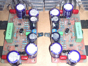
Aux channel preamp
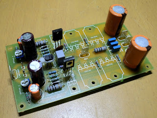
This one looks interesting. I have 8 of these tubes on hand, and they are nice golden NOS Russians. I am going to order this board too and see if there is a way to increase gain and to mod to a tone unit too
- Am I heading in the right direction with this board?
- How does it work without output transformers?
- Are there any output transformers that may enhance the task that I am asking of these?
- Are input transformers with this of any merit?
- Is it ok to run the output of this into the input of the tube headphone board?
- I would like to run a switching power supply instead of a "ring cow". Is this ok to do with this design? Should I take out the regulator stuff out of this board if I find a switching supply?
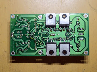
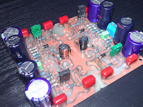
6N3 Preamplifier Circuit Board
This one is also attractive, but I'll only have the tube that comes with the kit
- Is this a better option?
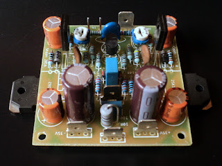
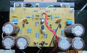
TR2 6DJ8 ECC88 E88CC 6922 Tube Buffer Pre-amplifier
The following is from another thread in the class D area and provides the background into what I am doing. Eventually, the hope is that I would have played with lots of gear and upgrades
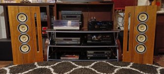
I am actively putting together two systems:
System 1 - 5.1 for our home which serves as home cinema and home studio and used for studio tasks usually about once a week. This is an open plan type home that contains the kitchen and adults bedding in one room. Another same sized room is attached, with an amenities' room separating the two. A full length room run alongside the two main rooms and serves as my workshop, large double sliding doors from main room to workshop. These areas are contained in a square house structure
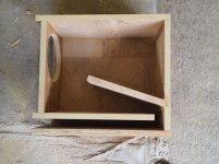
System 2 - 2.1 mobile box with 3 aux amplifier channels outputs, for a portable setup, which can supply extra amplification on demand with extra speakers. This will be installed in the workshop in a manner that allows easy removal. Mainly for listening to music while I am working, as well as for testing stuff without having to rip into the home system (I hope the logic for common device models is now apparent)
Request
The living room is not a place for a PA system, neither is the sound quality and ability of most of this sized PA systems out there for portable use acceptable. System 1 will be in operation here virtually 24/7.
Think of these as being in the same category as the high-end Japanese audiophile disc players that feature mic inputs. I do not believe that anyone would be upset about such a disc player being discussed in a Hi-fi forum, so please may I request that discussion on an amplifier with the same feature doesn't upset anyone's sensibilities
Please regard these as a Hi-fi want to be setup. Both will be used for audio and video reproduction and appreciation and when liquid courage hits the spot, these systems should invite one to grab something and let loose
Desired feature:
- An ability to keep electronic hardware and speaker driver models common to both systems
- Emphasis is on quality quite nighttime sound reproduction and ample headroom without loosing composure for other times
- Switch power supplies (desire to stay away from "ring cows")
- Tubey audio signature (prefer the sound of the 300b amp for audio)
- Engineered with the ability to input a live performer or two on demand (In other words, beautiful reproduction of prerecorded material, containing the "studio to mastering" process internally for a seamless jamalong)
- Low pass channels to be either about; 400 clean watts into 8 ohms - 400 clean watts into 2 ohms - 2 x 200 clean watts into 4 ohms each
- High pass channels to be about 100 watts clean into 4 ohms
This thread is for the tube devices that will be contained within
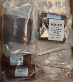
I have been saving for this project for a while, and in the meantime pouring over catalogues and specs and pestering folks with uneducated questions and ideas. Time to get to work on these, so I have ordered these items:
Signal IO
This unit will get fitted inside the amplifier case and provide most of the signal IO and act as the brains and system overall volume (has remote) as well as individual channel adjustment
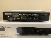
4K@60Hz HDMI 2.0 Audio Extractor Converter DTS AC3 5.1CH Digital Audio Decoder ARC SPDIF Coaxial PC-USB Bluetooth Audio Input
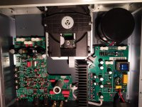
Amplification
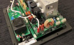
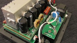
To be trailed as the low frequency amp
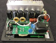
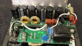
AIYIMA 500Wx2 Digital Power Amplifier (PSU on the board) x 1
To be trailed as the main channels amp and low frequency amp
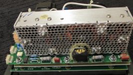
HIFI Power IRS2092 500W Mono channel Digital power amplifier x 5
+
Lusya Dual DC 36V Output LLC Soft Switch 500W Switching Power Supply x 1
To be trailed as the main channels amp and bench amp
TDA7492 Amp Class D High-Power Digital Amplifier Board 2x50W (to run in bridge mode as a mono amp) x 1
+
24V switching power supply board 4A 100W x 1
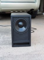
Speaker drivers
Low frequency
Dayton Audio RSS265HO-44 10" Reference Series HO DVC (delivered) x 1
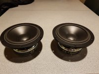
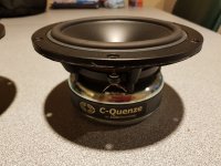
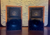
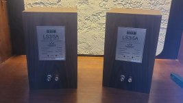
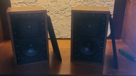
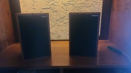
Main channels
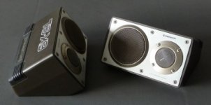
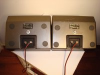
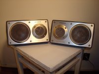
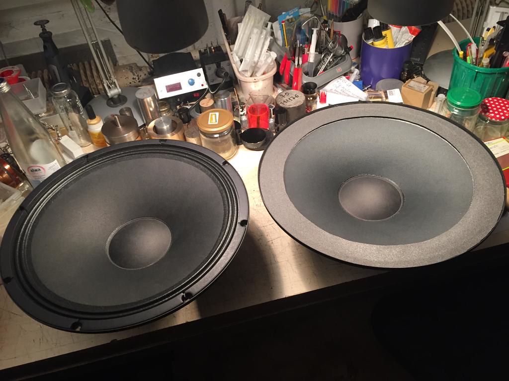
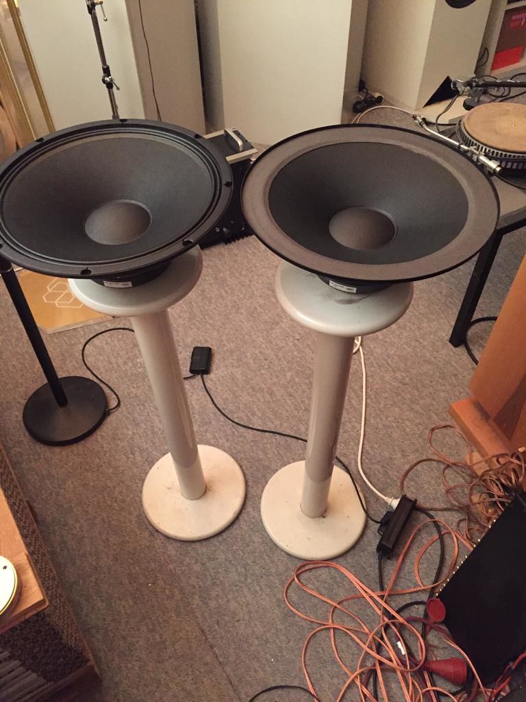
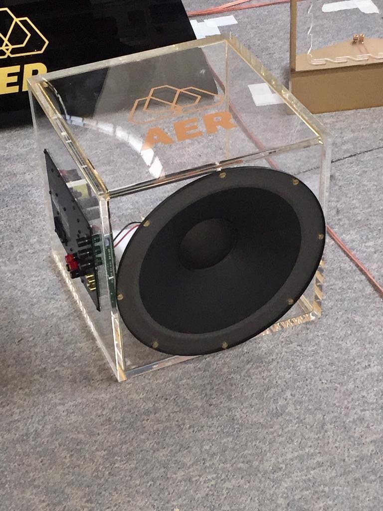
Already have a number of various pairs of bookshelf types on hand. Working on an interesting 6" coaxial speaker alongside this project, I am using some very interesting sounding drivers that I auditioned and bought, but I fear derision on my choice here
Reason to post thread
I am getting some promising looking kit that might help me acquired the desired sound system. Please guys, help me with peer review of my choices and suggestions to gear that I may not have noticed. I know create folks out there will have some great ideas too. Please help with mod suggestions as well as education pointers in anything I may be lacking. This will also be a log for me to help keep track of my project
Thanks and regards
Randy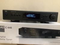


 Check at the end of this post)


 Moderator Edit: This thread split from here -