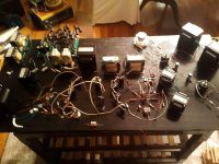
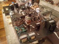
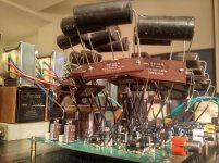
A little help needed by some fellow diyAudio Member from Slovakia (purchase at bazos.sk)

Dear fellow diyAudio comrade from Slovakia,

I'd like to do a purchase at bazos.sk, but due to not having a slovakian or czech telephone number (which is required there to identify) I cannot get the vendor's email adress and so I cannot contact him. Will you help me out please and get the email adress for me?

Best regards, Gerd

Has anyone powered their HiFi speakers with PA amplifiers successfully?

Just wondering if anyone here has tried this with low efficiency speakers. I have a pair of 6ft tall magnepan planar speakers that i restored that are very inefficient but people say that having huge power is the key to get the best out of them some people have audio amps with 500w rms per channel (megabucks) and being on a budget far below that pa seemed like a good idea-are there any amp brands that are particualarly good with resolution, detail etc?

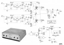
Wolfram 2400

Good evening

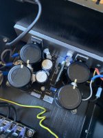
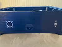
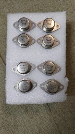
I have this wolfram 2400 here. It had damaged outputs and power supply. After replacing all the drivers for the power supply it would go straight into protect. No outputs, no 12v regulators, no power supply transistors.

After messing around for awhile removing and reinstalling drivers, 494, 393.. I've narrowed it down to everything is fine till I add the Q32/33 drivers. They drive the gates to Q52/53. With them out, no protect, every bank has nice drive. The base pads of Q32/33 have nice drive signals. One collector has ground, other power. The other half of the drivers connected to that circuit that drive Q49/50 (the other part of that transformer) is working fine...

Soon as I add the drivers Q32/33 it protects. Remove them, everything else seems fine. I've looked for solder bridges and stuff. Removed the diodes and stuff from that section. Checked everything and reinstalled. I'm stumped. Soon as I connect those 2 drivers on that one side. Without them, the other 7 sections work fine.

Any idea? Thanks in advance.

Attachments

  • 20200202_173336.jpg
    20200202_173336.jpg
    953.9 KB · Views: 160
  • 20200202_173145.jpg
    20200202_173145.jpg
    975.4 KB · Views: 171

LM1875 power output measurments

I measured the power output of one sample of an LM1875 IC at various supply voltages and non inductive loads. Supply voltage is the voltage measured directly on pins 3 & 5 while driving the load at measured output. I used a split supply, so 30v is +/- 15v, for example. Vout rms is measured right at the load resistor which is soldered to the amp board to minimize losses. Iout is the calculated rms output current.

Signal used was a low distortion sine wave at 1KHz. I used a spectrum analyzer to set the output at the point just before clipping (no clipping harmonics showing).

My recommendations: Since loudspeakers present a reactive load to the IC's output transistors and the transistors are current limited to about 4 amps across much of the output voltage range, I would not exceed the supply voltages that gave a 2.5 amp output. For example with a 4 ohm speaker, I would not use a supply voltage beyond 36v.

An externally hosted image should be here but it was not working when we last tested it.

An externally hosted image should be here but it was not working when we last tested it.

An externally hosted image should be here but it was not working when we last tested it.

"Funny" square waves - what do they mean?

Hi everybody
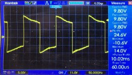
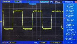
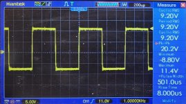
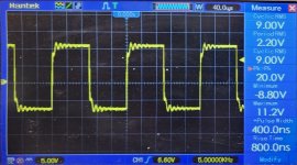
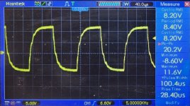
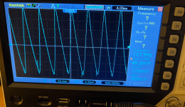
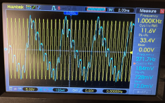
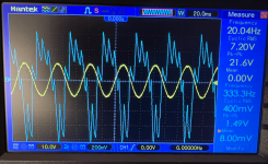
To address (potential) stability issues I'm testing a power amp (under construction) with different loads. Attached illustrations show the square wave response into 8R and into 8R with 100nF in parallel.
I hoped for a minor, and well-damped, overshoot for the capacitive load, but what I get more looks like some sort of "under-shoot", or over-damped over-shoot.....
Would anybody happen to have seen this before and know the cause?
The amp sounds and measures very well and my question is purely out of curiosity.
Thanks,
Nic
FY_UB_(PB_8R)_PS.png
FY_UB_(PB_8R__100n)_PS.png

Acoustic guitar cabinet question

I build my own speaker cabs for electric guitar. I have recently started putting together a rig for amplified acoustic and am using a 1x12 cab I built with an old JBL D123 for my acoustic guitar. The D123 is pretty full range and closer to a hifi PA speaker than a traditional electric guitar speaker, but it definitely lacks the high end sparkle. I’m thinking of possibly adding a tweeter to the cab, and a crossover. Looking for someone who would know if that might work, or if a 12” speaker is not appropriate for acoustic for some reason. Also looking for recommendations for the tweeter and XO, if this seems like an idea worth pursuing.

Blueglow SE KT88 Cathode Bias Resistor keeps blowing

Hi. I built the Blueglow KT88, pretty much to the design in the drawings, my first ever build. It was working great for a few months, then all of a sudden the left channel cathode bias resistor (500R 10W wirewound, #16 on the diagram) popped with a loud bang, flash, and a puff of acrid smoke. I had noticed some static and distortion in the 10 seconds or so before it blew.

So I replaced it, and after about 5 minutes of it being on it happened again, same static, same resistor, same pop. I was monitoring voltages at the time (B+ and the plate of the driver tube) and they were relatively normal, though the voltage on the driver plate was a little higher than I remember when I built it. I had just earlier checked voltage at the plates of the KT88s and they were normal at the time.

Bad tube? Bad bypass capacitor? Bad wiring? Bad ground? Something else in the chain? I know these components are all related and can affect each other in ways my novice mind can't comprehend just yet.

Before I go out and spend another $200+ on another KT88 matched pair, I wanted to see what you folks with much more knowledge on this have to say. What should my next troubleshooting step be?

Diagrams attached.

Thanks.
SE-KT88 v6 Amp Only - Blueglow - Final Build.png


SE-KT88 v6 PS Only - Blueglow - Final Build.png

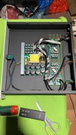
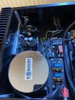
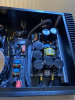
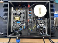
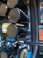
For Sale 2x Hypex Ncore NC500 stereo power amplifier

Hello. For sale a Hypex ncore nc500 power amplifier.
2 Hypex nc500 amp modules with Hypex buffer input and one smps 3k/700 with 3000w to gently feed both amps
it was a test amp built in a not a very fashion but well constructed and vented modushop case.
No more than 100hours of working time
I’m asking 690€ for the amp, shipping within EU included.
paypal fees, if apply, not included.

Attachments

  • CB494D2B-367A-4566-B14E-250A9E33DCB3.jpeg
    CB494D2B-367A-4566-B14E-250A9E33DCB3.jpeg
    186.2 KB · Views: 277
  • 76FDB47A-360F-4F1F-AB60-668BB1C7B7F6.jpeg
    76FDB47A-360F-4F1F-AB60-668BB1C7B7F6.jpeg
    164.5 KB · Views: 238
  • 709F5275-0062-445E-8D8B-999D43707263.jpeg
    709F5275-0062-445E-8D8B-999D43707263.jpeg
    117.2 KB · Views: 229
  • 099AA4B0-7774-4BBD-8ABD-3CE755212ADE.jpeg
    099AA4B0-7774-4BBD-8ABD-3CE755212ADE.jpeg
    132.2 KB · Views: 272
  • 51D1B552-3AED-4870-84DD-40651EE0C168.jpeg
    51D1B552-3AED-4870-84DD-40651EE0C168.jpeg
    141.2 KB · Views: 262
  • 2334B320-DE68-40AA-86F3-9538B3741E77.jpeg
    2334B320-DE68-40AA-86F3-9538B3741E77.jpeg
    105.8 KB · Views: 262

Marantz DD-82 DCC deck recap - test safety issue...

Hi,

have just finished recapping a Marantz DD-82 DCC player's R/W and Digital boards.

Unfortunately found a blown transistor during the process, which is driven from the motherboard's 8v regulated power supply.

The transistor appears to be part of the bias system for the read amp chip analogue inputs, which are protected from over-current by a 560R resistor (apparently intact for both channels).

I'd like to test the motherboard power supply with the recapped boards out of the system - any thoughts on the safety of doing that, or why the transistor failed much appreciated...

Service manual (fried transistor is Q103 bottom left on p.45):
Marantz DD-82 - Manual - Digital Compact Cassette Recorder - HiFi Engine

Actual alternative to 816/515 Altec

hello,

I received two empty 816A cabinets. In others times, I may reinstal products from GPA, but today specific order costs a lot considering each step from buying to door delivery.

I would like to find actual speakers with caracteristics close to original 816-8 or 515. I want to swap woofer without any adjustment as I can't do acoustics measures. I know it's not a cabinet for full range (100-1000Hz ?) but gently extending band will be nice.

thanks for advices.

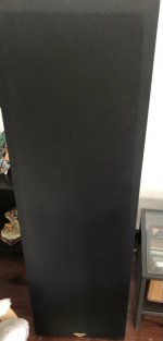
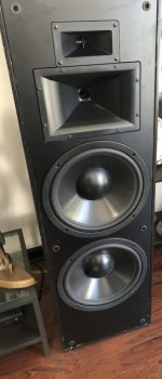
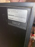
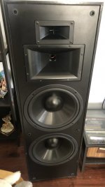
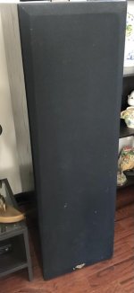
For sale - Klipsch KLF 30

Hello all,

Selling a pair of klipsch klf-30. All original..

Asking $1500 or best offer..
Pick up only in Mundelein IL

Thanks

Attachments

  • FBB93B07-325C-467E-8DA1-977099465935.jpeg
    FBB93B07-325C-467E-8DA1-977099465935.jpeg
    62.7 KB · Views: 166
  • 363C494D-794A-491A-8FF1-AFDE3584FEDB.jpeg
    363C494D-794A-491A-8FF1-AFDE3584FEDB.jpeg
    74.1 KB · Views: 165
  • 540596BC-2091-4E26-80D4-9B2D97AB66CE.jpeg
    540596BC-2091-4E26-80D4-9B2D97AB66CE.jpeg
    425.8 KB · Views: 183
  • 79AA951C-79FA-44E1-B6DB-059FF88C8B1C.jpeg
    79AA951C-79FA-44E1-B6DB-059FF88C8B1C.jpeg
    94.1 KB · Views: 166
  • 1A031CC6-A744-43D6-B8E5-C50D550D72BA.jpeg
    1A031CC6-A744-43D6-B8E5-C50D550D72BA.jpeg
    52.3 KB · Views: 169

PPI Amps

I recapped one of the customers amps so far .

He just brought me 2 more amps to replace the caps I already told him once again that the caps are fine and it’s just a waste of money .

But he insists on having them recapped .

I don’t think I rally made that much on the first amp .

Just wondering how much should I charge to recap both of these amps ? Say the parts come to $50 for all the caps and heatsink compound.

The amps are MOS25 and a MOS425

Reliability and maintenance of older amps?

I'm considering getting some second-hand amps for use in an actively crossed system. Attenuation will be at source (i.e. any amp volume control would remain set high) so I'm particularly keen that they're fairly low noise. I could consider AVRs, but IMO the ideal contenders would be power amps (or integrated amps with a by-passable pre-stage); most seem to have a SNR around 115dB or better.

I am tempted by used models from NAD such as the C326BEE, which can be got for about £200 here. But even though not massively old (15years?) they seem to have quite a lot of reliability issues being tackled on diyAydio. Things like protection circuits, overheating zeners, and electrolytics placed close to hot parts. Some Rotel power amps like the RB-970BX appear to have better build quality, and so might be more suited to maintaining as they age. For similar money they're already quite a lot older to begin with, though.

So i'm now wondering if the second-hand route is sensible, or likely to incur frequent and ongoing maintenance problems. I'm up to replacing old capacitors, though probably not skilled enough to diagnose any tricky faults that might develop. But (obviously) I'm no expert so wondered what more informed people on here think about this - plain daft, better choices etc?

Thanks, Kev

Grommes 240 conversion to TCJ EL84 (need help)

Hi all!

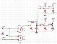
Grommes model 240. The schematic is attached.
I bought it because I liked the look.))
I replacemetnt all electrolytes caps and listened for a while. In my opinion, the sound not the most outstanding. But it was not bad.

But something went wrong. Not so long ago, one of the el84 tubes failed. (tube glowing blue). I replaced the quartet el84 and after a while it happened again.

Without becoming to find out what the problem is (probably in vain), I simply dismantled the entire amplifier and decided to restore the chassis first.

Now I thought, maybe it's better to change the circuit to something with more affordable tubes?

The reasons:
  • 7199 (6an8) and 6973 are not the cheapest and most affordable.
  • Plates el84 run at 425vdc. (Maybe that's why the tubes quickly fail.)
  • I can't find quality 500k potentiometers
  • PT is heating up. Many tubes with high current consumption.

So far I have settled on EL84 PP from TubeCad. With the replacement of 6N1P with E88CC.
One of the few tested circuits + not low voltage.

What's available.
OT - 9000 - Primary (no UL)
PT - 350-0-350 (200mA) + 3.15-0-3.15 (6A)
Rectifier - pair ez81 or CC (octal tube will not fit in the chassis)

Now I'm struggling with the power scheme.
With my beginner knowledge I can't find a neat way to get close to 340V from 700CT.

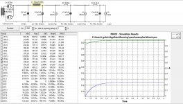
I have a choke LL1685 10H / 160mA / 130r (saturating current 230mA) But I'm not entirely sure that it will work as a LC filter with reg.capacitor. Without an choke input , i need a lot of dissipation in the resistors 800R 25W .

I would really appreciate any advice on a power supply circuit or an amplifier circuit.

Attachments

  • grommes_240_stereo_power_amplifier_sch.jpg
    grommes_240_stereo_power_amplifier_sch.jpg
    220.5 KB · Views: 255
  • PSUD2 EL84 PP.jpg
    PSUD2 EL84 PP.jpg
    299.9 KB · Views: 208
  • Schematic PSU el84 PP.jpg
    Schematic PSU el84 PP.jpg
    127.3 KB · Views: 222

audiohobby.eu trustworthy?

audiohobby.eu trustworthy? Yes!

Hi,

I just ordered a couple of caps through audiohobby.eu , a parts supplier in Europe.

The Mundorf MLytic AG 's I ordered were indicated "available" on the website. The moment I paid (trough Paypal) I got a mail telling me that there was no stock at the moment an that they would be backorderd.

Has anyone the same experience with this supplier or, hopefully, positive ones?

Thanks!

Marc

Shadzi - Bagby Ceramico

Anyone built or heard the Ceramico speakers from Java’s Shadzi and Jeff Bagby using the SB CAC drivers and 26CDC tweeter?

SB Acoustics Ceramicos Speaker Project by Javad Shadzi & Jeff bagby | Diyaudioparts

Crossover looks very simple, all standard 2nd order at approx. 200hz and 2800hz (single cap and coil on each crossover) with inverted mid and parallel twin 8” woofers in a 2cu.ft sealed box. I have done a quick boxsim model and it all checks out nicely and phase tracks extremely well.

All comment would be useful. Thanks in advance.

5.1 Digital Audio Control Circuit

Hello,

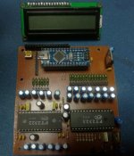
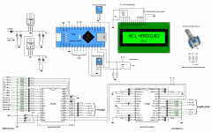
5.1 Control board project for sound system Bass, treble, mid, 3D effect, volume control of all channels Remote control LCD Encoder. PCB size 90.3x 100m and single deck design. There are source and library codes.

Login to view embedded media
07:00 General circuit description
02:22 Circuit test and explanations
07:35 👍
07:40 Ready sound modes
08:57 PCB description, encoder resistors
11:34 Arduino program, driver installation and settings
13:05 Arduino library upload
14:07 Arduino program upload (attention)
14:42 Determining and adding control codes to the code
16:22 preset sound modes code
16:27 Circuit Diagram
16:32 PCB Drawing (with Arduino module)
16:37 PCB Drawing (atmega328p only)
16:42 Surprise


source http://rcl-radio.ru/?p=62504

Attachments

  • ardupt.jpg
    ardupt.jpg
    55 KB · Views: 220
  • ardupt.zip
    ardupt.zip
    773.5 KB · Views: 122
  • ARDUPT-SCH.png.png
    ARDUPT-SCH.png.png
    374.1 KB · Views: 248

For Sale Micro-Audio SMPS 440-TK3 36vdc and Micra-P5 5v linear (SR7) Music Server Power Supply

Asking £1500/$1500, Includes high quality Mini-fit Jr umbilical cord to power Taiko ATX or HDPlex DC-DC. 2.1mm 5vdc out to power an audiophile USB card.

Quality build, full mundorf caps, Toroidy transformer into the Micra P5 (which is based on Paul Hynes SR7) - the Micra P5 is the 'Turbo' version. Can be adjusted between 5 to 12v.

Also includes common-mode choke/ inline filter.

A fantastic power supply, basically just built and used for review, see my comments here, and can be configured for 240v or 120v.

Any questions please ask, shipping from Oxford UK.

Attachments

  • D1597AE3-F7F8-4AD1-9BBF-79B83AA22554.jpeg
    D1597AE3-F7F8-4AD1-9BBF-79B83AA22554.jpeg
    430.3 KB · Views: 153
  • 661D828A-8804-4349-8098-4EFC751B9E43.jpeg
    661D828A-8804-4349-8098-4EFC751B9E43.jpeg
    443.1 KB · Views: 150
  • 5ADADDD2-1DB1-4A43-9A21-DAE3A1079409.jpeg
    5ADADDD2-1DB1-4A43-9A21-DAE3A1079409.jpeg
    477.8 KB · Views: 211
  • 8C8CABD5-7B78-403B-8A25-A05A5106778E.jpeg
    8C8CABD5-7B78-403B-8A25-A05A5106778E.jpeg
    599.3 KB · Views: 198
  • 5CEBDCC4-D2D8-44F5-AD8B-F741B83577BD.jpeg
    5CEBDCC4-D2D8-44F5-AD8B-F741B83577BD.jpeg
    453.4 KB · Views: 160
  • 2C44C483-1BC7-4C92-BE57-6645E869ED53.jpeg
    2C44C483-1BC7-4C92-BE57-6645E869ED53.jpeg
    498.6 KB · Views: 150
  • 9A9D98F7-3DE9-4D9F-A281-F3BF92C62452.jpeg
    9A9D98F7-3DE9-4D9F-A281-F3BF92C62452.jpeg
    377.5 KB · Views: 140

Tweeter making a faint hiss with no wires plugged into it?

I have a tweeter making a faint hiss with no wires plugged into it? as in not plugged into the amplifier or any circuit at all. just hooked up in parallel with a speaker. I dont know how it makes a noise but it does if I put my ear a few inches from it. the other one doesnt do that when unplugged i'm not sure how its possible for a tweeter to make any audible sound without even being plugged into anything at all.

Resistors- what type and tolerance do you tolerate?

I'm ordering parts for a small amplifier project and it's getting expensive in resistors alone, because they often come in a minimum pack of 20, which adds up quickly when I only need one or 2. I've been limiting myself to metal film resistors and ruling out carbon film resistors (up to 5% tolerance).

What resistors do you consider to be acceptable in your projects?

Cherry Waveguide TM Monitors

FC21293E-7F8E-4D35-A467-47E16C4883F8.jpeg
Got these here a number of years ago, designed the crossover, and now no longer have space for them.

$300 local pick-up in the great Seattle area.

A pair of large stand mount custom/DIY speakers using Vifa XT25TG30-04 and Dayton RS180-8. The waveguides are turned from cherry wood and profile is taken from Zaph Audio website. The enclosures are transmission line and scaled similarly to PMC twenty series. They were originally designed and tested using MiniDSP electronic crossover, but I designed a passive crossover that is currently being used.

The bass has great depth and extension for a monitor (bookshelf) speaker for the size due to the TL (transmission line) design, and they will not require a subwoofer for music for most listeners. The sound stage is great and the body and sense of space of the music reproduction is just as good.

Finishes aren’t my specialty, so use them as is or finish the cabinets with a veneer or coat of paint.
  • Like
Reactions: Bryguy and manniraj

Upcycling Microwave Transformers into Output Transformers

I recently decided to try to upcycle a microwave oven transformer into an output transformer with roughly a 2500:24 ohm impedance ratio. I chose a turns ratio of 1500:150 merely because those are round numbers. I didn't want to make this any more complicated than strictly necessary since I've never tried it before. It took a fair amount of time and patience, but I have both. Microwave iron is so readily available that I figure that someone else may have a need to know how this turned out for me. I challenge anyone to try the same instead of sending yet another dead microwave oven to the landfill. I am not claiming that this experimental transformer is "just as good" as any factory made transformer. That is entirely subjective in my opinion. It does sound great to my unqualified ear though.

I put together a test setup consisting of a 12AT7 gain stage coupled to a 6AS7G dual power triode for the output stage, given that it has such low output impedance. I take it that the 6AS7G has much lower "technical" Z than 2500 ohms, but I got far and away the best results with what I have here. The transformer that I compared this one to is an Edcor GSXE10-2.5k - 16ohm since that's the closest match that I have on hand. I intend to try this with smaller iron in the future for a headphone amplifier.

The microwave iron is freakishly huge for that purpose, but it's still in the experimental stage and it was easier to wind, given it's large size. The microwave iron that I have is already in an E-I configuration, and the "E" and "I" were bead welded together. I cut the welds with a grinder and pryed the "I" off, exposing the factory windings. I removed all three of those, along with the shunts. On one piece of iron, I ground the middle leg of the "E" down by a couple of mm to increase the air gap, but didn't notice any improvement over leaving it alone. I 3d-printed a bobbin for the new iron out of Nylon, and put it on a hand-cranked jig to wind it.

On my first attempt, I wound the primary and the secondary both in one large go each, laying the secondary entirely on top of the primary. I used 28awg magnet wire for both, since I have a large amount of it that's been salvaged from shaded pole electric motors, and isolated the windings from each other using Kapton tape. The results of that one were mixed. I wasn't overly careful with getting the turns very neat and even, and the result was a square wave output that had a considerable amount of rolloff. That is, the "corners" of the waveform were rounded on all frequencies. Not sure of "rolloff" is the correct term for that, but there it is.

On the second attempt, I carefully wound four layers of the primary, then one layer of the secondary, then another four of the primary, etc until finished. I then spliced the segments together. I again isolated the primary and secondary at all transitions with Kapton tape. I fed a square wave into the amp at several frequencies and documented the output on a scope. I don't yet know how to calculate THD, so I apologize for not including that data. I observed near-identical performance at low frequencies. The edges of the waveform were somewhat rounded off on the DIY transformer at high frequencies though. Not so much that I found it unpleasant to the ear. I really like it in fact, and am excited that it worked anywhere near as well as it did. The trebel is nice and clear, but it's not as sharp and piercing here as I've seen with some other setups.

So anyway, there it is. The iron on the DIY trafo is a little janky looking, but one would be surprised what a little sandpaper and spray paint can do to remedy that. There's certainly room for improvement overall, but it's workable and I think that's pretty awesome.

Attachments

  • a 50Hz DIY OPY.jpg
    a 50Hz DIY OPY.jpg
    346.8 KB · Views: 353
  • a 50Hz Edcor OPT.jpg
    a 50Hz Edcor OPT.jpg
    338.4 KB · Views: 211
  • b 1KHz DIY OPT.jpg
    b 1KHz DIY OPT.jpg
    425.4 KB · Views: 219
  • b 1KHz Edcor OPT.jpg
    b 1KHz Edcor OPT.jpg
    515.9 KB · Views: 194
  • c 5KHz Edcor OPT.jpg
    c 5KHz Edcor OPT.jpg
    395.4 KB · Views: 211
  • c 5KHz DIY OPT.jpg
    c 5KHz DIY OPT.jpg
    450.9 KB · Views: 328
  • d DIY Transformer 2 crop.jpg
    d DIY Transformer 2 crop.jpg
    684.6 KB · Views: 460
  • d DIY Transformer crop.jpg
    d DIY Transformer crop.jpg
    445.2 KB · Views: 602
  • f Test Amp Schematic (more corrected).jpg
    f Test Amp Schematic (more corrected).jpg
    59 KB · Views: 411

Multiple Caps PSU question

Hi All,
previously posted on the Stan Curtis 60W Class a Thread.
I'm pretty new to this, so would like to ask a few questions:
I'm going to make a pair of these and in relation to smoothing caps in a PSU, the example above uses 2x 15000uf 'Sprague 36D' caps rated at 50V. These are obsolete, although there are new versions available and similar caps also available from other manufacturers. So I have a couple of questions if I may:
Whats the effect on a transformer feeding two of these giants as opposed to say 8 x 4700uf in parallel? in regards to the rectifier, is the charging time for the smaller caps quicker?
As a reference PSU, my Electrocompaniet EC25's have 4 x 4700 uf for one side feeding one set of rails (I think) and two 2200uf on the other.
I hear references to ripple current and ESR, the larger value caps do have higher ratings for both Ripple and lower ESR - certainly in the examples I'm looking at. Ripple is quoted at 100Hz. But what is the effect when smaller caps are in parallel? Do they smaller caps values add, multiply or neither? So if the ratings do add or multiply - this is better?
I have plenty of space in the chassis I'm using so either is viable, but I'd be interested in your thoughts.
Kind Regards
Joe

1 order crossover help

Hi guys ,
I'm an imbecile with electronics and hard-wired crossover elements ,this is why I would like to ask for help.
My woofer set up contains two DaytoAudio rs225 wired in parallel to get 4 Ohm`s . For one of the woofers, I would like to apply 1 order crossover limiting woofer to 200 Hz. I'm using active 4way crossover and would like simplify to 3 -way.

1666122709638.png


1666122867686.png

I guess, the main question is what type of coil should be used for the best result ?
  • Air core coils
  • Ferrite core coils
  • Copper foil coils
  • Iron core coils
  • Litz wire wax coils
  • Toroidal coils
Each driver is 8 Ohm's ,when wired parallel combined are 4 Ohm`s , what L1 (1 order filter) should be used ,for 8 Ohms driver or for 4 Ohm driver.

Thank you in advance for participating 🙂

Buzzing bass because of rubber

Hey there,

I am new here but would like some advice on fixing the subwoofer of my speaker. I got a pair of B&W DM320N and with one of them the bass buzzes.
I found out that if I pull it up every so slightly it gets fixed but when I remove my finger it starts buzzing again. I have no knowledge of speaker repair, so I am asking for some advice.
Login to view embedded media

A way to help core saturation in SE

Hi,
I was looking at this schematic of Pierre Johannet published on "L'Audiophile" and called "Super Némésis Compensé", seen on this French site:
https://www.bonavolta.ch/hobby/fr/audio/2sk135se.htm#2SK135 Single-Ended 3

1663483130194.png


"To improve the bass response and use a transformer without an air gap (larger primary inductance), it uses a second primary winding to avoid saturation of the magnetic core. This primary is powered (without any signal) by a second 2SK135, the current passing in an opposite direction cancels the magnetic field of the first primary."

I was thinking about a compromise to avoid any extra power consumption: use a custom dedicated winding on the OPT to supply the driver of the SE power tube, then helping to avoid core saturation (air gap still needed).

Searching for possible previous examples of this idea, I've then found Philips EL3541 amp with a similar approach (look point 70):
philips_el3541_recorder_sch.pdf_1[1].png


I was planning to ask Toroidy a specific SE OPT, and I would like to ask what specifications are needed to be communicated to get this advantage on core saturation.

Thank you all,
Roberto

Tannoy S900 Superdual value (CPA 12.3 /CPA 10 stack)

Hi, I have a pair of working Tannoy Superdual Series s900 stacks and if anyone is able to help me understand their value it'd be appreciated - I am planning to sell.

There is no documentation attached but I believe there is a CPA 10 mounted to the top of each CPA 12.3B stack.

As far as I can tell, they are both fully working, although in very used aesthetic condition, pictures attached. There is a little cosmetic damage to the CPA 10 woofers but they otherwise work great.

Each CPA 12.B stack consists of 2x 12" Long throw bass units, type 3112 - and 1x 12" Superdual Constant directivity dual concentric type 3138

Whilst they are not currently on, I have the speaker grills

There are more details here: http://www.lmcaudio.co.uk/assets/pdf/S900.pdf
and here (see CPA 12.3B): tannoy

Your help would be appreciated, and if you're interested in purchasing please get in touch,

Thank you!

Attachments

  • S900.pdf
    S900.pdf
    192.8 KB · Views: 163
  • IMG_0413.jpg
    IMG_0413.jpg
    887.2 KB · Views: 384
  • IMG_0414.JPG
    IMG_0414.JPG
    204.7 KB · Views: 339
  • IMG_0415.JPG
    IMG_0415.JPG
    242.2 KB · Views: 485
  • IMG_0419.JPG
    IMG_0419.JPG
    214.8 KB · Views: 449
  • IMG_0430.JPG
    IMG_0430.JPG
    475.6 KB · Views: 357

FS Kester 24-6337-9703 .4mm (.015 in)450gr

Kester solder (all info in title) Perfect to solder PC board and as good as many after market solder only if .Board must be clean like a new penny(I know these are out since long time now 😉) and wire (from capa, resistor,transistor etc). must be clean and with .4mm there is no extra solder on board and now and only this solder sound exc..Price as follow : :1 roll $30. + shipping, 3 roll $80. free shipping (this free shipping offer is good only for Tuesday Oct.25th ) it is promotional offer from Canada post and I give up to you . Price are in US$ and sale free shipping good only for US conus/Canada . Outside north america or need more than 3 roll send me PM
IMG_7585.JPG
IMG_7676.JPG
send me PM
IMG_7500.JPG

AC Heater for better Sound quality? Waste of time or worth a try

Hello everyone,

I have a single ended 211 power amplifier that used to have AC heaters on the 211, and then got 'upgraded' to have DC heaters from the same AC transformer output at 10.5V.

This occurred around 20 yrs ago and I can't recall why (I think it was considered a good idea at the time). The circuit is super simple 47000 uF cap to ground, 0.82R in series followed by a 47000 uF to ground with a 2.2 uF Wima bypass. The original balance pot on the cathode remains in place but obviously there is very little AC left and whilst it can be used to sort of reduce the minimal hum it does not really make much difference.

The amp is pretty quiet and causes no problems BUT I keep reading about the better SQ of AC heated filaments in DHT and I have no memory of the before and after DC heater with this amp, it was a long time ago and I was not actually using it then, a friend was.

So for a morning or probably more like a days work and some cable to try this - what do you think, likely to be beneficial in terms of potential sound quality improvements or likely to make very little difference apart form adding some hummmmm!

Thanks for sharing your thoughts and experience

Adcom GFA-5400 Ripple - Recap or Not Recap

I just acquired an Adcom GFA-5400. It is in very good shape and very clean inside and out. I don't know the use history but it looks like the previous owner had not used it very much. It is a Version 2 (i.e., made in China with Jamecon caps and contains a protection board).

I don't want to recap it if it is not necessary, and I don't want to pull the caps out to measure them. Instead I measured the ripple and wanted to see if the results would tell me whether the caps are good or not. The results are attached, but I don't have a reference so I don't know if they're good or not. Note that I'm not trying to assess the amp design. I'm just trying to see if the kind of ripple observed is normal or not for this amp, and hope from this info I can decide if the caps need to be replaced or not.

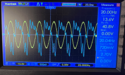
At 20Hz 40Vp-p (into 5 ohm load), I got a ripple of 2.7Vp-p in one rail. That works out to 2.5% sag in the upper rail. I think that is not too bad but what is more concerning is that the other channel sagged 20% less. Also, when I cranked up the power (forgot how high but definitely not at full power) the amp suddenly shut down which also caused my scope to shut down and reboot. The last time my scope shut down and reboot happened when I connected the negative output of a Class D amp to the ground (forgot it was a full bridge), which caused big sparks to fly. There was no damage and everything started up fine again, but I did not attempt to measure at higher power at 20 Hz.

The scope captures are attached. Can we tell if the supply caps are in good shape or not from these measurements?

Attachments

  • idle.PNG
    idle.PNG
    1,022.9 KB · Views: 61
  • 1K_27W.PNG
    1K_27W.PNG
    1.1 MB · Views: 67
  • 20Hz_10W.PNG
    20Hz_10W.PNG
    1,000.5 KB · Views: 67
  • 20Hz_37W.PNG
    20Hz_37W.PNG
    860.3 KB · Views: 66

Bi-Amping how is the power shared?

Hi there

Bit of a basic question I’m afraid, but cannot find the answer.

If I’m Bi-amping an amplifier which has two channels, 125W @4ohm each, does each lot of 125w go to each channel evenly?

IE- 125W to the woofer and 125w to the tweeter?

Or does the crossover I create mean that I get something like 200W to the woofer and 50W to the tweeter?

If the former is correct this would seem to waste loads of power.


Thanks!

Akai CS-F21 buzz after it warms up

Hello,
I'm fixing my fathers Akai CS-F21 cassette player.
Last time it has been used as cassette player was around 2008, later I was using it as headphone preamp I would say it was around 2014 to 2016.
After that it was stored at room temperatures.

I had changed the belts, cleaned heads and other moving parts.
I can't see any obvious problems, caps look good, no oxidation, ...

It can play and record well, I'm using cro2 tapes and man it sounds nice.

Problem is that after about 30 minutes of playback music gets cut out by a loud buzz. If I stop and when I hit play I can hear the music for a split second. Buzz can be seen on db meters and if I change cassete type (cro2, normal metal), buzz also changes, buzz does not change when I move dolby switch and volume can still be controlled with output level switch.
Buzz is not there if I use it as preamp (REC PAUSE), but I had not tryed to actually record while problem is there.

I don't know much about cassette players and what stages it has (got to do some reading on that) , but my diagnose is that problems is somewhere between the tape head and it's preamp, but before dolby or output preamp.
My plan is to take the pcb out and inspect for bad solder joints and if I cant find anything obvious I will try to find schematic and do some signal testing with the scope and maybee listening on some test points with headphones / small speaker.

My question is:
Can tape head go bad and cause a problem only once it warms up?

Did anyone had a problem like that and fixed it?


Here is the video of the buzz:
Video

Thank you

I need to replace my mega XLS10 tapped horn - help! (HT)

Hi everyone,

I'm currently enjoying a single XLS10 in a mega tapped horn enclosure that a friend designed for me. Unravelled, the waveguide is about 4 metres long! It's powered by a Hipex PSC2.400 with DSP.

This supports the rest of my HT setup, comprising of a Yamaha RX3050 AVR and a 9 channel Atmos configuration using DLS speakers (for 5.1.4 in total).

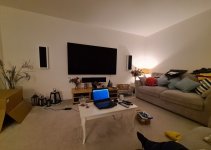
So now, the point. The current sub enclosure sits happily in one corner of the room and due to future renovation plans, there will no longer be room for it in its current incarnation. So I need to come up with an alternative solution.

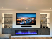
We're looking to build a 'media wall', with a storage bench going all the way along the wall (approx 5m wide). This will have a selection of cupboards and drawers to house AV equipment, media discs, etc.

So obviously I'm looking at the possibility of integrating a subwoofer(s) within this new furniture. I don't want to go to the hassle of trying to re-work the tapped horn design into it, so really I'm looking at sealed or possibly ported enclosures.

Now I've read a few threads on here about people's experiences with XLS10s, I'm familiar with the passive radiator concept, and also the port requirements for the driver (which may not be an issue with the amount of space I may have in the overall cabinet).

I do have two spare brand XLS10 drivers that I would love to use, so I'm opening this design challenge to the experts on here to see what's possible!

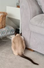
I've attached a few photos showing the current space, a cat investigating sub bass, and a basis wall example (mine won't have a fake fireplace).

Look forward to your thoughts!

Attachments

  • 1-LOGO2.png
    1-LOGO2.png
    1 MB · Views: 158
  • Screenshot_20221007_115203.jpg
    Screenshot_20221007_115203.jpg
    157.8 KB · Views: 151
  • Screenshot_20221007_115116.jpg
    Screenshot_20221007_115116.jpg
    332.3 KB · Views: 145

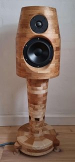
Design Comments

I would like some technical comments on my design. That is, not whether it is beautiful or ugly.

Since the cabinet is cylindrical, the bass will penetrate much deeper into the cabinet than the tweeter.
I have tried to take this into account by making a slope at the top of the cabinet (12 degrees).
The Tweeter thus comes further back, so that bass and tweeter are now almost in line as if they were placed in a flat baffle.
They are therefore not in the acoustic center, so the slope should be greater or the tweeter should be recessed deeper
into the cabinet and there should then be a waveguide in the cabinet. But is it a problem that the treble plays up a bit
when the bass plays straight ahead. Wilson for example uses almost the opposite principle so that all drivers point directly to it
towards the listener.

Inside, there should be very little opportunity for standing waves. There are 12 edges that are offset from each other
and the front goes very deep into the cabinet, and is very uneven, so there are no large flat surfaces facing each other.

The bass reflex comes out through the base, so the base is part of the speaker.

Attachments

  • Spike.jpg
    Spike.jpg
    282.1 KB · Views: 180
  • Like
Reactions: vineethkumar01

Improve PSRR of LTP w/ emitter current source

Hi there, i have no clues about PSRR to start about, i was trying some caps here and there but it didnt help. What i do to see PSRR in spice is in spite of putting a DC source (48v) i put a sine source with the same dc offset and something like 50mv 30Khz singnal. The LTP seems to amplify the noise in the same way it amplifies signal, and we are talking about 58dB in sim. I think it could be even more with some matched bc560c, or other higher hfe device. The general idea is to make a mic preamp that can give u +4dBu from mic in as minimalist as posible. At the momment i got about +15dBu from a 10mv signal and about -10dBv from a 1mv signal. So i could simply add an attenuator not to clip power amp if the mic is too sensitive, but the PSRR is awfull! Any thoughts?

1666145411590.png

Attachments

  • 1666145386841.png
    1666145386841.png
    6.1 KB · Views: 114

Amp 5 channels and 2 transformers

Not exactly a DIY question, but I guess this is the best place to ask. I have seen 2 channel amp with a single transformer and the single transformer feeds the two channels, Dual mono amps where each channel has its own transformer, but how about a 5 channel amp with two transformers? How is the fifth channel powered? Can the two transformer power the fifth channel or one transformer powers 2 channels and the other powers 3 channels or the two transformers power is pooled into a single source and powers all 5 channels?

B2 Spice and the 723 regulator

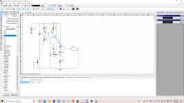
I've been trying to develop a precision voltage reference for HV power supplies and I'm using B2 Spice for simulations and I found it's pretty darn accurate. I have pictured below a curcuit I simulated, which is the voltage reference amp contained in the UA723 regulator,and it matches real world results very good! I used general purpose BJTs and a J111 for the ccs, and the Vref and Noise output is spot on. which is 7.25VDC and a noise output of 2.5uV. the HV Vref curcuit I put togther has a lower noise figure of 150nV, which I was surprised!

Attachments

  • 2B364F56-E10E-4483-AACF-A4489543537A.png
    2B364F56-E10E-4483-AACF-A4489543537A.png
    59.7 KB · Views: 144
  • Like
Reactions: Johno

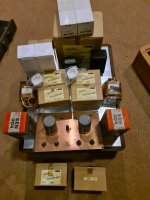
Various Drivers For Sale

CDT HD-6 About fifty hours use, some of the black finish came off the front of one basket when I removed the Fast Rings.

Wacecor TW030WA04 Tweeters Over Two Years Of Use In My Car. One Has Low Output, One Works Fine.

JBL MS-52 set, very low hours use. One of the tweeters has low output and only 1 tweeter grill, otherrwise perfect working order.

SB Acoustics SB65WBAC25-4 Less Than One Hour Of Use.

Wavecor FR090WA02 Fullrange Less Than 1 Hour Of Use.

Wavecor FR070WA03 Fullrange About fifty Hours Of Use. One has a small dent in the dust cap and one has a small dent near the surround.

Wavecor TW022WA04 Tweeters About fifty Hours Of Use.

Wavecor TW022WA02 Tweeters About Two Hours Of Use.

$250. Plus Shipping

Attachments

  • SPEAKERS FOR SALe.jpg
    SPEAKERS FOR SALe.jpg
    780 KB · Views: 117

Krell KRS-2 with KRSP-2 power supply. External transformer needed..

Just got from an auction this beautiful Krell KRS-2 with KRSP-2 power supply. BUT the external box with the transformer is missing.
From what I see in the first pic: 4 transformers for 2 voltages and 2 channels.
Should be not difficult to build a box with these.

Question: Does somebody know about the needed transform secondary voltages / ratings?

PS: The cable from the KRSP-2 to the KRS-2 with the Lemo connector I do have.

Thanks
GM

Attachments

  • krell_krs_power_supply_intern.jpg
    krell_krs_power_supply_intern.jpg
    268.3 KB · Views: 108
  • krell_krs-2_inside.jpg
    krell_krs-2_inside.jpg
    392.4 KB · Views: 127
  • krs-2_backside.jpg
    krs-2_backside.jpg
    197.2 KB · Views: 109

how to unmute or reset DVD player directly without remote control?

i forgot to hide the remote control of dvd player that already broken (plus volume and some button not work) when my friend and his son visit me last week. his son press minus volume until the sound is gone, so because of that, my dvd player can't sound. i try find remote control on online shop with same to this but not find it. finally find general remote then i bought it. unfortunetely that remote doesn't work after i input every 3 digit (trial and error).
is there any way to reset the dvd player direct at the dvd player so the sound coming again?

ICEPower 500ASP + 500A or 2x 500ASP?

I bought an ICE 500ASP and paired it with a 500A module for a 2 channel amplifier a couple of years ago. I've been reading recently that even though they are meant to work together, its more recommended to use 2x 500ASP modules instead. I know the 1000A is bandwidth limited, as opposed to the 500A. I've seen the charts in the datasheets and they seem to have some minor differences, but is it worth it?

Looking for FaitalPRO 12PR320 8Ω FRD and ZMA files

Hi all, first post on this forum so apologies if I'm in the wrong place. I'm looking for 0deg and 30deg FRD files for

FaitalPRO 12PR320 8Ω and FaitalPRO 12PR330 8Ω​

along with the associated ZMA file. Does anyone know where to find these? I've looked everywhere but I don't have the tools (or drivers) to measure these for myself.

If these aren't available, is it possible or stupid to use VituixCAD with a roughly similar driver to at least get a rough idea of the initial crossover which could be modified once the speaker is built?

For context, I'm building a ~95dB 3 way PA with ~50L enclosure using this as the mid-bass, B&C 5MND38 8ohm as mid and Monacor DT300 8ohm as tweeter.

Any help would be massively appreciated!

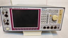
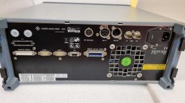
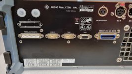
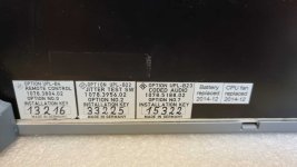
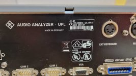
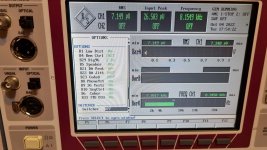
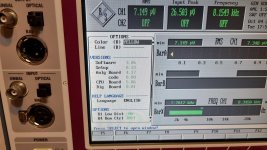
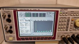
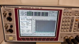
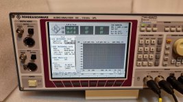
For Sale Rohde & Schwarz UPL B4 B29 B22 B23 Audio Analyzer

Hello.

I have for sell well known audio analyzer Rohde & Schwarz UPL 1078.2008K06

It has installed options: B4 B29 B22 B23

Analyzer have some scratches on the case, but front panel is in very good condition. No feet, it was working in rack. no other accessories, only EU power cord.
Fan's in good conditions, they not very loud.

Price: SOLD + shipping
Shipping almost worldwide.

20221004_161146.jpg20221004_161153.jpg20221004_161200.jpg20221004_161251.jpg20221004_161307.jpg20221004_161342.jpg20221004_161502.jpg20221004_161507.jpg20221004_161516.jpg20221004_161519.jpg20221004_161909.jpg20221004_161930.jpg20221004_162019.jpg20221004_162032.jpg20221004_163617.jpg20221004_163650.jpg20221004_164254.jpg

MacAudio z4100 not working

Hi there!
I'm new here so I hope I'm posting this in the right place. I have a MacAudio Car audio amplifier z4100 which I'm trying to fix.

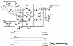
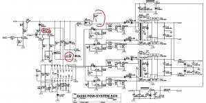
It seams I have high voltage coming from Protect signal to TL494 IC controller , turning the overload red led ON. There isn't audio at any of the outputs.

There are some set of transistors (C5198 & A1941 pairs) getting extremelly hot together with their 5W ceramic resistance. (mainly Channel 3 and 4)

I uploaded some Schematics thet I found of z4200 model which is quite similar. The marks in red were not done by me. So, it doesn't refer to my problem.

Any help will be appreciated!

Thanks!

Attachments

  • 1773618100_1300813065.jpg
    1773618100_1300813065.jpg
    127.8 KB · Views: 105
  • 3633528300_1300811089.jpg
    3633528300_1300811089.jpg
    165 KB · Views: 123

Can i build Phonostage with AD1 DHT like this?

I'm planning to make a Phonostage with a Triode tube with an existing Hashimoto Transformer. This schematic is just a draft, with a Tamura TKS22 input with an Indirect Heather triode REN904 ( 20 - 30Mu) - Hashimoto Hl 20k (OTL) and Hashimoto EQL ( RIAA) amplifier and an AD1 DHT as preamp.
Can it run well? any suggestion? Thank You.

Attachments

  • phono DHT2.JPG
    phono DHT2.JPG
    68.4 KB · Views: 261
  • 20221018_124651.jpg
    20221018_124651.jpg
    530.3 KB · Views: 234

Current Drive for Headphones & The Super Linear Transconductance Amplifier

As probably the last circuit we shall build for headphone amplifiers, we want to find out how they sound under current drive.
This is not only known for loudspeakers, but also for headphones, especially for planar magnetics.

The circuit is an evolution from our earlier Pioneer Super Linear Headphone Amplifier.
https://www.diyaudio.com/forums/headphone-systems/313163-pioneer-super-linear-circuit.html
Only now it has been modified to output current instead of voltage.
Many of the aspects of the SL Voltage such as device matching, etc. still applies.

You can read about the article here :
http://xen-audio.com/documents/cdha/Current Drive for Headphones Public 181006.pdf


Happy reading,
Patrick

.

Attachments

  • 180715 SL Trans Top.jpg
    180715 SL Trans Top.jpg
    111.8 KB · Views: 3,411

ADCOM GFA-5802 Thermal LED

Was listening to my amp and suddenly heard a hum and my left channel thermal LED is on and no sound from that channel. Right channel is functional. When powering off the system or unplug the AC connector, the LED goes off.
Already checked T40 (85-degree Thermal Breaker) and it is ok (compared left and right channel and they both are short in normal room temperature).
Any idea what else could cause the thermal LED to stay on (Thermal protection always activated)?

Sony TA-4650 Oscillating

Hi, I've been refreshing this amplifier over the past year in stages. First the PS then on to the amplifier board. I replace all the the electrolytic caps first and it was so far so good. Listened to it for a few months then decided replace the non-electrolytic caps. The outputs transistors are good but the amp is now oscillating. Being somewhat frustrated now I decided to bring into an audio service center in Chicago that is an authorized repair some very high-end gear and is very familiar with V-fets. Anyway, they believe the problem is with the ceramic caps that I replaced with poly-caps in the feedback circuit that is causing the oscillation. Everything else checked out fine on the amp. So my question is it possible the the makeup of the cap is critical here? Ceramic vs Poly? I don't post much here but I would appreciate some feedback on my situation. Thanks!

CCS and voltage references

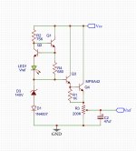
I've being working with constant current sources in designing a voltage reference for valve based power supplies, and I started out using a single MOSFET(DN2540- TO-92). Im only using TO-92 packages to save board space, because this will be a plug in module for the power supply.

Below I have an example of what I have arrived at. the VR stablizer is also variable. I would welcome any opinions from those that have worked with current sources. All active BJTs are MPAS42 divices. With this CCS Im able to deliver 2X the amount of current to the zener and temp comp diode.

Attachments

  • B9AB1D59-D251-4C4E-93E0-0DD9026E181E.jpeg
    B9AB1D59-D251-4C4E-93E0-0DD9026E181E.jpeg
    334.7 KB · Views: 231

Quadral Aurum 9 sad story short

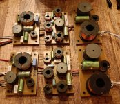
Hallo to audio lovers. Past few days i decided to sell my 30years old Infinityes as im tired of watching them and buy something old/new for me.So Aurums by Quadrals caugth my eye so i went for it. The have beautyful design and good choice of speakers inside wich are 2x8"woofers, 2x5" midds and on top RIBBON TWEETER..mmm nice. Wood finish is exelent !! So i buy them and brought them home..After few minutes i notice that is not much clearance in sound and everything is muddy sounding!? W*F.. i just buy.. Im schoked. Soo after good nite rest i started testing and speakers are all ok. Woofers and bass port are in faze, midds are allso good placed and tweeters 100% okay, so only thing i could think of was FILTERS !! So i open the speakers to find out "##€"#€##"€€€."!"";+€-*:#;€.. What in gods name was Quadral thinking?? See picture as i cant talk now.. I must stop..Sorry

Attachments

  • IMG_20221016_192928.jpg
    IMG_20221016_192928.jpg
    669.4 KB · Views: 204

Sub for Electrostats

I am currently using the Gradient SW63 with the Quad ESL. The woofers are tired and the XO unit is getting noisy. I began looking at re-driver'ing the Gradient but then started considering other possibilities. Surely in the past 30 years there are better approaches that I can put four new drivers into.

The Gradient kept up well with the Quad. I have another set of subs, the Dayton RSS315, which put out plenty, but just don't sync with the speed of the Quad. And they start to drop fast after 40Hz.

I like the concept of the dipole and have been looking at a number of H, W, Z, V etc. configurations. The Linkwitz design for his LX521 seems to have some interesting advantages but I'd really prefer to avoid the active equalization.

In the end, I'm open to whatever the best solution is- I'm not married to any particular approach.

Thanks in advance for the suggestions and guidance.

Three way horn system

Three way horn system (4 way at the moment)

Hello all. After some time of lurking, this is my first post. Recently I have heard my friends horn system. As mid-bass he uses w-bin folded horns with one 12" Isophon driver, roughly 100x100x80 cm in size, then something like "smith" radial horn with a Coral 1" driver and Coral tweeters at the top, all with active crossovers. Except for PA, my first experience with horns.

What I noticed, the bass guitar, snare, kick, voices - all almost like alive during a rehearsal (I am musician too). I could even feel the bass, although it could not be very low. The music was playing loud, but it did not feel lound until i tried to speak. Awesome. I have a few questions.
What would be the bass-mid crossover frequency for such a system?
I hope I could use compression drivers and horns from around 1kHz, but I am afraid bass horns just won't fit into my room. What bass system would you recommend? I do not need very low frequencies, I would like to have this tight sounding bass. As far as drivers concerns, I am more or less limited to Monacor, Eminence, B&C, Selenium, Beyma or RCF.

Update after 11 years🙂 (BTW, the horn system described above was identified meanwhile as the Danish Jealvox clone)

The current setup (October 17th, 2019) is (per side):
40 Hz bass horn with 15" speaker - Cerwin Vega inspired design - up to 120 Hz (one more per side is waiting to be installed)
JBL4560-like front horn with 15" Black Widow speaker - up to 600 Hz (to be replaced with John Inlow 135 Hz midbass horn in a few months)
JBL2445 + JBL2380A clone - up to 4.5 k, passive XO to HF (gorgeous Yuichi 290 horns are in production)
Beyma CP385Nd on 2380A with a custom 3D printed adapter (will be installed soon - the prototype needs some little adjustments)

The HF + MF will most probably be one day with a single 1.4" driver (maybe BMS4554) either on the Yuichi or another large horn.

Each side is using 3 channels of amplification (SE EL34 for the MF+HF) and one t.racks DSPmini for crossover, delays and EQ.
Projects by fanatics, for fanatics
Get answers and advice for everyone wanting to learn the art of audio.
Join the Community
507,654
Members
7,882,884
Messages

Filter

Forum Statistics

Threads
405,967
Messages
7,882,884
Members
507,654
Latest member
HelioRizzo