Buffer with digital potentiometer for mx50se

Hi all, i need help with a project based on a mx50se, i need a pot volume, from what I understood i can't just put a pot between input and power amplifier because I would go to modify the impedance by raising or lowering the pot, i need a buffer o preamplifier, i tried a few of preamp based on ne5532 and i don't really like it, they sound really bad, i also found a clone of naim nac 42 by ljm on aliexpress, but it have high gain and with the high gain of the mx50se i would reach saturation with half pot, so i can reduce the gain of mx50se and use another pot, something like 20k but i don't know if this is a good idea, most important, I haven't tried this preamp yet , otherwise i can use a buffer, i think this is the best choice, but i don't really know where i can found a good project not too much expensive with a good quality, most important i need a digital potentiometer that can i managed by i2c with arduino or something like that.

NEW 600watt TPA3255 Mono Bass board

Hi, my Rockford bass amp I had been using in my main system has spat it's dummy, so is now a paper weight. As I had a spare 3255 in my 2nd system I inserted that into my main rig. Boy what an improvement after it passed though my Electronic X-over set to 100hz.
So I went hunting for a replacement & found this thing on Ali-Express. (who having been giving great service over the last several months, some orders reaching me within 8 days, with full tracking support of the parcel, very impressive)
https://www.aliexpress.com/item/1005003335861622.html?spm=a2g0o.order_detail.0.0.4558f19cnlnwud
The cost was a remarkable $45 & I also orders from the same supplier a 35 VDC 5A SMPS for $18
https://www.aliexpress.com/item/33031309629.html?spm=a2g0o.order_detail.0.0.4558f19cnlnwud

So when they arrive it will be very interesting to see how good they sound as a bass amp & how the unit holds up

Cheers

Taps, FFT Length, Resolution, Latency, etc

This is a basic question, but I cannot find a good reference. Can someone point me to what is meant by and interactions between 'taps', FFT (Fast-Fourier Transform, I assume) length, resolution, and latency? The first two are configurable values used in constructing convolution filters in RePhase, and the latter two are from Equalizer APO's system analysis tab.

I'm aware that generally increasing the number of taps increases the 'accuracy' (trying to avoid incorrectly using resolution since I don't know the technical meaning) of a filter, but I don't know how what it actually is nor do I know how that interacts with the other three items above.

What I find particularly confusing is that Equalizer APO's analysis tab allows you to set different 'resolution values', and doing so seems to show that the relationship between resolution and CPU use is convex - it's highest at the lowest resolution settings and decreases for a bit before increasing again. I would have expected this to be closer to a linear relationship - CPU use decreases as resolution decreases, but again, not really know what is meant by resolution in a technical sense, I don't know how to make sense of this.

Finally, if Equalizer APO says channel A has latency of 700ms, does this roughly mean that the audio signal has a lag of 700ms? For example, if all other channels have a latency of 700ms, does this mean there's a delay of 700ms before audio starts but everything is processed and output 'in time' while if all other channels had a latency of 690ms, channel A would be 10ms behind the rest?

Thanks. I'm more than happy to read up on good references as this is something I'd like to understand anyway. I'm a mathematician but as an algebraic geometer, never had a need to learn things like Fourier Transform let alone study signal processing.
  • Like
Reactions: dgerg

HELP! Cyrus dAD3 cd player-instaling Q module (18 bit Analog Devices AD1861)

I find a 18bit Q module for my Cyrus dAD3 cd player and i can not get analog signal out.
Cd player put Q mark on display so that means Qmodule is recognized.
I put jumpers from STD to UGD,clean al connections with wd40,try to put many times Q module in and out,try to put jummpers back to STD,and then every thing again.
And no signal from analog out.
If i take Q module out and put jummpers back on STD,i have signal. But with Q module i cant get no signal. Can anybody help me?
Cd player reads cd always and on the screen everything looks ok,Q mark is there,cd running,but no analog signal.
Help!
20221023_205121.jpg

20221023_205000.jpg

20221023_204906.jpg

20221023_204747.jpg

20221023_204732.jpg

20221023_204822.jpg

20221023_204845.jpg

  • Locked
6N16 12x preamp srpp/cathode follower with printed circuit board design.

Hi folks,

Last month i designed/build a small preamp/buffer on a dutch forum. I like to share my experience also on this forum. I used the 6N16 miniature tube in a srpp/ cathode follewer setup. Further i designed a circuitboard and try to use cheap and simple parts for preamp and powersupply.

Some features :

Input voltage: from 10 to 1000mV
Amplification: 12x
Anode voltage rimple: <0.1mV
Output power on delay: 20 seconds.
Printed cicuit board: 100 x 160 mm (eurocard format)

Usable for Dac I/V conversion, CD player output buffer, Preamp, inputbuffer for Hypex class D amps.

6n16buffer.jpg


6n16print.jpg


Below see printdesign in the pdf file. Powersupply can be seperated from preamp.

http://www.monstercore.nl/6n16print.pdf

Have fun with this schematic.

printl.jpg


Ronny

  • Locked
DIY Friendly Low Noise, Low Cost Power Suppy 5...15V 400mA

Triggered by this thread : https://www.diyaudio.com/community/threads/compact-diy-friendly-dual-tps7a3301-power-supply.290858/ .
And the high prices and availability of low noise regulators. And problems with handeling smd parts.
I designed a realy quiet power supply with first a capacitor multiplier and then a TPS7A3301 regulator in TO220-7 housing(Cheap and throuhole).
Totalcost with transfomer,PCB and all parts about 20 euro.
I use two of them for dual rail suppy +/- 15V.

Schematic

View attachment 1096604

R1,Q1,C11 are part of the capacitor multiplier. With 200mA load the ripple before the TPS7A33 is only 5mV. With only 3300uf capactor it was 265mV.
After the TPS7A33 noise/ripple is lower then -120db, this is the limit of my measure equipment.

Transfomer

View attachment 1096552

TPS7A3301 TO220-7 housing.
Got the part for free, from the TI sample program.

View attachment 1096557

PCB

View attachment 1102185

PCB size is 50 x 100 mm. Ordered at JLCPCB for 8 euro(5 pcs).
Gerber files for ordering see below.

Ronny
  • Like
Reactions: justinhd

1kW LLC converter

After completing a fullbridge and halfbridge converter and using them to power my amp projects, I continued to investigate other topologies to overcome the disadvantages of the above:
1.EMI
2.Large inductors on outputs
3.Difficulties caused light loading
4.Hard switching and others

I found this forum's help essential to the success of my projects and I am again seeking your inputs and comments.

A big thanks for all help in the past ,I have been bit by the promise of the LLC converter and I want to scale one to a kW.I have read many appnotes from Fairchild,Onsemi and others and one thing stands out,PFC frontend required.. therfore a 1kW PFC will be needed for reliable operation.Fairchild,onsemi and STmicro have controllers dedicated for this along with excellent appnotes and tools.(AND8257,AND8255,AN2450 and AND8311/D.I will start with the LLC design first and to open the project I would like to present a simulation of a dual output llc using LTspice(free spice simualtor).The attached file set includes all models and libraries for the simulation.Included is a single output sim(see appnote AND8255).

Attachments

Screech!! CEC power relay for existing audio system?

I'm using a MiniDSP 2x4HD as equalizer, electronic crossover, and volume control to an amplifier and speaker arrangement. The MiniDSP gets its signal via TOSLINK fiber out of a recent model Sony Bravia TV. The power amplifiers are class D with signal sensing and shutdown and I leave the amplifiers otherwise turned on all the time. It all works great, I get the sound from the good speakers and big amplifiers and the TV does the picture, with its internal speakers turned off.

BUT when the TV is turned off, and after some random number of hours go by, the system will start to make a horrifiicly loud hashy SCREECH sound! Either the Sony TV is emitting random garbage IR onto the TOSLINK cable (seems doubtful, but who knows?) or the 2x4HD's optical input's signal threshold is drifting down to where it is responding to noise and translating it into ghastly audio blasting (seems more likely).

I've been dealing with it for the past year by just remembering to mute the MiniDSP (via remote) after turning the TV off. But when I forget, like last night, I'm afraid the problem could burn out my speakers, possibly even be a fire hazard, if I'm not around?? And in my soon-to-be new living arrangement the TV will likely be operated by others including a child, so I need a simple solution for this.

Is there some sort of box that will switch AC power of external equipment, responding the HDMI CEC as if it were an HDMI sound bar for power on/off? I've tried googling for this and all I've come up with are "HDMI switches", which I don't need -- and I certainly don't need more remote controls!

Or some other way around this problem? Hard to believe no one else has had need to auto-switch power to the stereo when TV is turned off...

Thanks
Bill

Amazon Echo dot 3 or 4 in 2.1 with a generic activ subwoofer question

I've been trying for months to connect an active subwoofer to a stereo pair of Echo dot 3 and 4 to reinforce the bass because I don't want to buy an Echo sub and above all, I have two or three subwoofers lying around and are useless.
I have almost tried all the configurations (with Jack 3.5, wifi, bluetooth, Echo flex) but nothing to do, I can't get everything to work at the same time, it's either the stereo pair that works, either the subwoofer but never the whole thing.
has anyone succeeded?

A Heretical Unity gain line stage

Unity gain line stage

This is the story of a project that mutated. It started out with some surprising measurements on a batch of ECC81s; despite their relegation to the lowest of castes by the tube fashionistas, I found that these are very low distortion tubes. Also cheap and readily available. So, thought I, let's make a new preamp. The old one is about to turn 25 and was built in the days when my sources were much different than they are now.

By the time I was done, the ECC81s were history (they're finding application in my next published circuit, a small power amp with LED biasing). And the circuit had mutated into various species, each of which had their own virtues and faults. One of them, at least, is actually pretty novel. They all perform well. And they're all suitable for pedagogical exposition and auditory enjoyment.

My format here will be a three stage proposition (with an intermission to consider power supplies), starting with the simplest, most conventional circuit, moving on to a somewhat unconventional approach, then mutating off into outer space. Each stage will anticipate the next so that this series can be followed as a set of construction/instruction projects.

I’ve gone into rather gory detail about choices of components and operating points; one great priority for me is using parts on hand whenever possible. If I specify those parts, no one else can duplicate it. But with knowledge of how the parts were chosen and how things can be juggled around to accommodate other parts, a relative novice can alter things readily with a good chance of success.

So, here we go....

First step: Define requirements

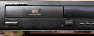
These days, a preamp is almost redundant. Signal sources in my living room include CD, DVD, satellite/cable, and MP3, not an untypical mix. All have roughly 2V output at a low source impedance. My phono will get its own dedicated step-up/equalizer designed to output a similar voltage. So, we need at least 5 inputs, all high level. My power amps are of normal sensitivity (as probably are yours), so we really only need unity gain. A10K input impedance is fine- there will be no weedy sources allowed in MY system!

There's another reason for the choice of 10K as the input impedance- I'm sold on the use of input transformers. Wait, wait, I see you starting to click to the next thread, but hear me out: given the multiplicity and uncontrollability of grounds in a multi-source system like mine, there is a decided advantage to galvanic isolation. There's also a decided advantage to common mode rejection in a noisy (electromagnetically speaking) environment. And at these signal levels and impedances, you can get good bandwidth and very low distortion. As a bonus, the transformer will do a nice job of limiting bandwidth; though some people have a religious belief that more bandwidth is better, there's precious little (ok, NO) evidence that extending bandwidth beyond 20-25kHz is audible. That's no surprise- we don't have sources that provide signal energy more than an octave above that, at best (and rarely). There is plenty of evidence that the consequences of transferring high frequency junk through the power amp ARE often audible, even with the limitations of program material. The transformer specified will take us to 90kHz or a little higher while not passing AM radio or our local CB operators. The canonical taxi drivers will not be considered. That bandwidth should give us margin to accommodate any currently available signal source and any contemplated sources for the next decade or two. See the white papers at www.jensentransformers.com for detailed and lucid discussion of transformers and grounding.

As far as output drive abilities, we can calculate what we might need. The maximum length of interconnect I am likely to use is 3 meters (say, 10 feet). That will also accommodate 99.9% of the rest of the world. With an interconnect capacitance of 150pF/m (the worst I could find), we need to drive 450pF. Call it 500pF. The power amp will have an input impedance of 10K at minimum, and might add another 500pF of input capacitance, if it's a particularly nasty design. So we have our worst case load: 10Kohm paralleled with 1000pF. The unit should also be perfectly stable into this or any other likely load- this is a restricted club and we do not take kindly to stray oscillations sneaking in the back door.

We want the unit to be quiet. Hum and hiss should be inaudible. Let the analog tape or mike preamps annoy you, not your preamp. Noise below -80 dB from full output is acceptable in real rooms, so let's go a factor of ten better and insist on -100dB.

OK, we know what we want to accomplish. How do we do it?

Second step: Basic design outline

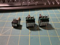
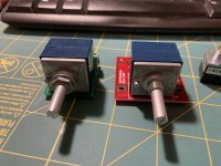
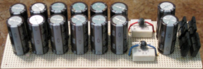
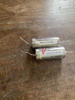
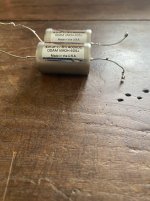
Starting at the input, my choice of transformer is the Jensen JT11-P1. It's a 1:1 input transformer, optimized for a 10K load, with great balance and common-mode rejection, low distortion, and not terribly pricy in the US. In the UK, Sowter makes a similar-looking unit, the 3575; the specs aren't quite as nice-looking, but it appears pretty satisfactory. The CMLI-15/15C from Cinemaq is supposed to be equivalent to the Jensen, but at a lower price. If you really want to go on the cheap, I’ve heard good reports about the Edcor WSM 10K/10K, and they're under $10 a pop.

We don't want to load the transformer with capacitance, we need a low output impedance, we need unity gain- are you thinking what I'm thinking? Sure you are- we want a cathode follower. Ultra-high input impedance, ultra-low input capacitance, high power supply rejection, easy to stabilize, ultra-low distortion, and low parts count. Yes, I see you wriggling in your chair a bit- you read somewhere that cathode followers sound awful and have all kinds of performance problems. Or a "knowledgeable" buddy of yours told you that. Whatever. It's just a crock, and it's a crock that was fired in the kiln of incompetent design and filled with the ejecta of tragic ignorance. Ask your buddy if he'd turn down an immaculate pair of Marantz 9s.

We will not do an incompetent design.

Let's see what a proper design will entail. Worst case, we want to drive a 500pF load while retaining the bandwidth that the input transformer allowed us. The source impedance and the cable's shunt capacitance form a first-order low-pass filter with a 3dB down frequency of f3 = 1/(6.28*Zout*C). Rearranging terms to solve for Zout, we see that for a 90kHz bandwidth, we need a source Z of about 1.8Kohm. That's pretty doable. But we also have to consider how much current will be needed to drive the load to the maximum voltage. If we assume a 2 volt input sensitivity (that's RMS; peak will be about 2.8V) for our power amp, the signal current needed to drive the 1000pF load capacitance to the full voltage while maintaining the 90kHz bandwidth is about i = 1.6mA. Using a rule of thumb, we arbitrarily dictate that the standing cathode follower current ought to be at least several times higher, just to have margin and to minimize distortion. So let's say we need 10-15mA running through the cathode follower at minimum.

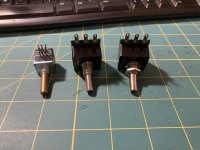
We're now in a position to select a tube. There are a lot of candidates which are happy at the desired current, two very common ones being the 6SN7 and the 6DJ8/ECC88. These also have the considerable virtue of being cheap and easy to find. Recalling that the output impedance of a cathode follower is about 1/gm, we can check the suitability. The 6SN7 has a transconductance of 2.5-3 mA/V, which translates to an output impedance of 300-400 ohm. Add a cathode stopper (more about that later) and we're up to roughly 1K, well within what we need. Similarly, a 6DJ8/ECC88 at 10mA will have a transconductance about three times higher, resulting in a base source impedance of roughly 100-150 ohm. So from this standpoint, either will work. The 6SN7 is a lower distortion tube, but with the inherent feedback of a cathode follower, both tubes are likely to have exceptionally low distortion at these signal levels.

The ECC88 is a winner in this application because of its plate voltage requirements: less than half what is needed for the 6SN7. So low, in fact, that the B+ supply can be made with a standard isolation transformer, and still have enough headroom for active regulation. As a bonus, the higher transconductance translates into a lower noise floor.

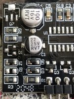
A constant current source as a cathode load will help make biasing easier. It will also ease some of the voltage requirements as we will see in the detailed design description. I have been leery of their use in the past, based mostly on unsatisfactory experiences with FET current sources that were fashionable back in the days of Jimmy Carter. Several writers convinced me to use discrete bipolar CCS and I've been delighted with the results. They're cheap, perform well, and are quite reliable, in all ways a vast improvement on those awful two-legged devils of my youth. A pentode also can make a fine current source, but it needs lots of voltage, more chassis room, more heater supply current, higher cost, higher parts count, lower reliability, separate heater supplies... but it's a perfectly valid choice. I just didn't choose it. Either way, it will be made adjustable: adjustability gives the tweaker loads and loads of fun opportunity and flexibility to play with operating points and alternative tube choices.

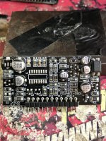
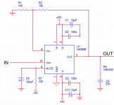
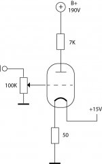
I think we're ready to float a preliminary design out there and start assigning component values. The basic topology looks like this:

An externally hosted image should be here but it was not working when we last tested it.

TKD and Alps Blue Volume Pots

Asking $80 for all of these sold together as one lot, which is <50% of retail:

TKD 2CP2511 100K monos (used once)

TKD 2CP601 100K (used once)

Two Alps blue stereo, one is 50K, one is 100K (used once)

Attachments

  • IMG_1102.jpg
    IMG_1102.jpg
    418.4 KB · Views: 126
  • IMG_1103.jpg
    IMG_1103.jpg
    405.5 KB · Views: 121
  • IMG_1104.jpg
    IMG_1104.jpg
    402.8 KB · Views: 118
  • IMG_1105.jpg
    IMG_1105.jpg
    385.3 KB · Views: 125
  • IMG_1106.jpg
    IMG_1106.jpg
    401.6 KB · Views: 120

LM3886 PCB vs Point-to-Point (with data)

Update:
  • More comprehensive measurements available here: Post #30
  • THD+N vs Frequency for inverting vs non-inverting configuration can be found here: Post #36
  • THD+N vs Output Power for inverting vs non-inverting configuration can be found here: Post #38
  • THD+N with star grounding is available here: Post #40


First off, let me say that I do not intend to cause a shouting match between the PCB lovers and the Point-to-Point (P2P) enthusiasts. I just noticed something interesting while prototyping so I decided to investigate and document it...

The story is this: I'm designing an amp based on the LM3886. My intent is to improve dramatically on the performance of the original LM3886. The final amp will reside on a PCB, but I figured I would build a prototype first. That way I could get the bugs ironed out before committing big bucks to a PCB fab run. I built the prototype using P2P wiring as that's the quickest and I expected it to provide as good performance as a PCB. Indeed the performance at 1 kHz was reasonably close to the data sheet figures.

However, I was rather surprised when I measured the THD versus frequency. At 20 kHz the THD was an order of magnitude worse than the data sheet would indicate. This was rather surprising to me as the P2P circuit is pretty tight. The feedback network is right on the IC pins. As is the decoupling caps. The distance from the 1000 uF supply caps to the IC is not more than 40~50 mm. The circuit was fed from a quality lab supply.

I decided to spin a quick prototype PCB. On the PCB is the exact same circuit as I used for the P2P setup. All the components came from the same batches of parts. Yet, on the PCB, I am able to reproduce the data sheet performance. The THD is much improved. The ground plane on the PCB is connected to the power ground. Signal ground runs as a separate trace and joins the power ground at the center between the two 1000 uF supply caps.

As seen from the transient responses, neither circuit exhibits tendencies towards instability. The transient response is nice and well controlled for both the PCB and the P2P circuit.

The schematic attached shows the main parts of the circuit. In addition, there are two 1000 uF electrolytic caps bypassed by two 47 nF ceramic caps where the power enters the board.

I suspect the return paths for the various electric fields in the circuit are better controlled in the PCB-based circuit. I am guessing that is the explanation for the difference.

The abrupt change in THD around 1.5 W is caused by range switching in the HP 8903A distortion analyzer. The uptick in THD above 6 W for the 20 Hz trace is caused by brownout of the power supply.

The supply voltage was +/-28 V.

Equipment: HP 8903A distortion analyzer. Tektronix 2465B 400 MHz oscilloscope (using 20 MHz bandwidth setting to avoid interference from a nearby FM transmitter). HP 6228B power supply.

Just thought I'd share...

~Tom

Attachments

  • LM3886_Schematic.png
    LM3886_Schematic.png
    17.3 KB · Views: 8,519
  • LM3886_PCB_Transient10kHz.jpg
    LM3886_PCB_Transient10kHz.jpg
    271.1 KB · Views: 8,240
  • LM3886_PCB_THD_vs_Freq_15W.png
    LM3886_PCB_THD_vs_Freq_15W.png
    80.2 KB · Views: 7,819
  • LM3886_PCB_THD_PowerFreq.png
    LM3886_PCB_THD_PowerFreq.png
    135.6 KB · Views: 7,598
  • LM3886_P2P_15R22nF.jpg
    LM3886_P2P_15R22nF.jpg
    241.5 KB · Views: 7,542
  • LM3886_P2P_THD_vs_Freq_15W.png
    LM3886_P2P_THD_vs_Freq_15W.png
    82.8 KB · Views: 2,062
  • LM3886_P2P_THD_vs_PowerFreq_15R22nF.png
    LM3886_P2P_THD_vs_PowerFreq_15R22nF.png
    119.9 KB · Views: 2,326
  • LM3886_PCB.jpg
    LM3886_PCB.jpg
    348.7 KB · Views: 4,065
  • LM3886_P2P_Full.jpg
    LM3886_P2P_Full.jpg
    419.5 KB · Views: 4,026
  • LM3886_P2P_Detail.jpg
    LM3886_P2P_Detail.jpg
    425.5 KB · Views: 3,635

Point 2 Point (no PCB) for TDA7293, TDA7294, TDA7295, TDA7296.

I received a request for a build thread with TDA7294 point to point.
Please feel free to add comments, questions and suggestions.
DMOS = Lateral Fet = Power MosFET, and are inside these chips.

Here it is step by step, with photos. . .
311109d1352534370-point-2-point-no-pcb-tda7293-tda7294-tda7295-tda7296-pinout.gif

The above photo shows TDA7294/5/6 pinout.

311133d1352541824-point-2-point-no-pcb-tda7293-tda7294-tda7295-tda7296-schematic.gif

The above photo shows the schematic. It is especially suited to under-volting applications.
Here is a new full power schematic that doesn't require a preamp <click link
Note that TDA7294S and TDA7293 have advanced features at pins 5, 11, and 12. We shouldn't ground those. I've no idea if my TDA7294 chip has those features, so I'm going to remove those pins by wiggling them; with the benefit of more room for soldering.

311111d1352534370-point-2-point-no-pcb-tda7293-tda7294-tda7295-tda7296-pinremove.jpg

Now, the pins marked N.C. (5, 11, 12) are definitely not connected, and 12 pins is easier than 15. At this time, I'd like to mention that if you favor parts swapping for fine tuning and quality control, then you may rather use PCB boards for the first build. Here are some compatible kit boards. <--link

311112d1352534370-point-2-point-no-pcb-tda7293-tda7294-tda7295-tda7296-pinbend.jpg

The above photo shows: Bending the V+ pins (8, 15) almost to the chip face, bending the V- pins (7, 13) up a bit and then bending the ground pins (1, 4) to midway. This is for rails horizontally across the chip. I've also bent the small signal, down away from the power pins, and spread them very slightly.

311115d1352534370-point-2-point-no-pcb-tda7293-tda7294-tda7295-tda7296-rails.jpg

The above photo shows V+ and V- rails with ground at center. I used Gel Flux for assuring good connections done easier.
Those are low-ESR 220u caps. Optionally, you can use parallel pairs of ordinary 100u caps (makes low loss 200u).

311116d1352534370-point-2-point-no-pcb-tda7293-tda7294-tda7295-tda7296-railbypass.jpg

The above photo shows nanofared caps added to V+ and V- for HF bypass duties.
Also shown is 2u polyester at rail to rail (one cap from V+ to V-) for quality control.

311113d1352534370-point-2-point-no-pcb-tda7293-tda7294-tda7295-tda7296-feedbackbootstrap.jpg

From boostrap pin (6), the 47u boostrap capacitor goes to output pin (14).
The above photo also shows 60k feedback resistor from output pin (14) to inverting input pin (2). That feedback resistor pictured is a parallel pair of 120k, for quality control, and fortunately doubly sturdy with minimized inductance.
Feel free to sleeve anything with heat shrink tubing if you want to (even in that case, please do have some air space in-between).
EASIER BUILD?: If you're going to do any fine tuning or want an easier build, then consider allowing the pins to hang down below the heatsink and put the feedback resistor on back so that you can change values easily and there is much more room to build small signal area. Tone changes by both operating voltage and gain setting, and you will want to fine tune that to your own preferences.
LACKING A PREAMP?: Click Here for alternate higher gain schematic.

311114d1352534370-point-2-point-no-pcb-tda7293-tda7294-tda7295-tda7296-mutestandby.jpg

The above photo shows:
Standby (9) to V+ via 22k
Standby (9) to ground via 10u.
Mute (10) to V+ via 10k

311117d1352534370-point-2-point-no-pcb-tda7293-tda7294-tda7295-tda7296-input.jpg

The above photo (bottom side) shows:
220u NFB cap at ground pin (1)
2.7k (carbon) feedback-shunt resistor from NFB cap to to inverting input pin (2)
10k (metal film) input load from ground rail to non-inverting input pin (3)
Notes:
The 220u NFB cap is for authentic chip, but if cull/fake use 100u or smaller NFB cap.
Cable for input and cable for speaker can be added before attaching chip to heatsink.
RF filtering of speaker output RC (6.8R and nanofareds cap) can be added at speaker jack.
RF filtering of input can be added with 1M||220p from + to - at the small signal input cable
Suggested input cap size is 1u (or smaller) and may be at the output of volume pot.
If volume pot is omitted, the input cap size of 1u (or smaller) can be at the RCA jack.

311118d1352534370-point-2-point-no-pcb-tda7293-tda7294-tda7295-tda7296-completed.jpg

And there it is, TDA729X point to point.

Voltage and current note:
Authentic chips are capable of the specs listed in their datasheets; however, please check ST's Authorized Reseller list to see if you bought or can buy from a reliable source. If you have any reason to suspect that your chip may be either fake or cull or misbehave, please use 4400u (or more) worth of "output cap" (capacitance in series to speaker blocks DC accidents) as a speaker protector, and use 8 ohm speakers. A parallel pair of 2200u creates a low loss 4400u cap suitable for output cap (parallel pair of 3300u creates a low loss 6600u output cap for larger speakers); however, it may be less expensive to purchase authentic chips. Of course mains fuse and speaker jack fuses are good too. Authentic ST chips (from authorized reseller) can drive both 8 ohm and 4 ohm speakers at high power.

First startup:
Use "output cap" to protect your test speaker and use safety bulb test to protect amplifier.

Transformer for TDA729x chips:
TDA7293, 24+24vac toroid or 48vct (24,0,24vac) 5a
TDA7294, 22+22vac toroid or 44vct (22,0,22vac) 5a
TDA7295, 20+20vac toroid or 40vct (20,0,20vac) 4a
TDA7296, 18+18vac toroid or 36vct (18,0,18vac) 3a
Cull/Fake, 15+15vac toroid or 30vct (15,0,15vac) 2a

Power supply:
343386d1366310480-point-2-point-no-pcb-tda7293-tda7294-tda7295-tda7296-power-005.jpg
  • Like
Reactions: deanznz

Charity Auction: 2 complete Miro AD1862 DACs

Miro's DAC is a brilliant implementation of the AD1862 non-oversampling R-2R DAC chip, which not only sounds great but lends itself to all sorts of experimentation.

You can read more about the DAC here.

The Auction

I'm auctioning two completed DAC boards to raise funds for DIYaudio's preferred charities: Donations to two great charities – diyAudio Store .

Both causes are great and you're free to choose, but perhaps consider the increase in suicide/suicide attempts during COVID.

Because you'll pay by showing me the receipt from your donation, 100.0% of funds will go to the charity.

I'll mail the DACs to the winners anywhere in the world* at my cost. Insurance and any import duties are on you.
* Where served by the US and your country's postal service.

The DACs

diyaudioauctionpic.jpeg


Both DACs were built and tested by me, using Kester SN63 solder and good components including brand 2 new AD1862N from Rochester Electronics. Panasonic FR, Nichicon, Wima MKP caps on the digital side and Wima MKS on the audio side. I/V resistors are 1.5k ohm General Resistance (Rhopoint) 8G16D and are socketed if you decide you want something even more esoteric.

They both sound good but each is packaged a little differently.

The Experimenter DAC has sockets for DIP op amps and the audio-side electrolytic caps, allowing you to test and tune. Panasonic FR caps and 4898, 4627 and 828 op amps are included to get you started.

The Listener DAC has LM6171 SOIC op amps and Elma Silmic II audio-side electrolytics soldered to the board and is ready to make your ears happy.

Remember that the auction is for the DAC boards only, before you can listen you'll need to provide an i2s converter for whatever data source you're using and good quality +/-5VDC and +/-12VDC power supplies.

The Rules:

You don't have to be a diyaudio member to bid, but maybe you should join, eh?

The Auction is what we here in Virginia farm country call "by the each." Bid a price per board, and the winning bidder can buy one or both at the winning bid price (x2 if taking both boards). If the winner only takes one board, I give the next-highest bidder a chance to buy the other board at their bid price, going down the list if that bidder declines.

Bidding is easy - reply to this thread with your bid, keep watching to see if you get outbid, then bid higher.

Bidding is open now and ends at 1600 UTC/GMT on Saturday 26 June 2021. The official countdown timer is here

The winning bidder must donate within 24 hours, else I'll go to the next bidder.

Good luck and please be generous!

FS: Assembled Sound Card Interface / AC RMS voltmeter by P. Millet

I purchased this about two weeks ago from a member here. Three days later my car stalled out at work and I had to get repairs done to the tune of $470, which dipped in to my ‘fun’ money and thus, I am selling the soundcard interface to recoup some of my funds.

The seller had lined the case in copper foil and also used the current limit bulbs that are supposed to reduce noise.

I’m asking $225 shipped, CONUS (or $210+shipping internationally).

-- SOLD --

I’ll attach pictures later when I get back to my phone and can upload them.

WTB Jaycar 5.6mH inductor

A long shot, but somebody may have a spare singleton sitting around.
I have one I was playing around with and now I want to use that value in a project for stereo speakers.
Of course I could buy a single cored coil of the same value but then OCD might kick in and I might hear artifacts that are not there. Also willing to sell this one and buy a matched pair.
Negotiable around the old retail price plus postage

Diy test equipment collection thread

Hello everyone if there is a thread already like this one I apologize and maybe some kind soul would link it here? 🙂 If there isn't one , maybe we can start one and pin it?

I am looking to start a thread where we can collect smart/nice to have DIY equipment that will help with Everything that comes close to DIY Audio. Or just a fun little project to build. Then when there is a lot of them , we can make a poll and get a top 10 most useful or something 🙂 just post whatever good threds you can find so there can be a big collection of them 🙂

this one is usfull
Simpel no math transformer snubber test jig
https://www.diyaudio.com/community/...rmer-snubber-using-quasimodo-test-jig.243100/

Zeners across unused primary taps?

I just received a pair of used UTC push pull output transformers with a tapped primary. They are designed for 5K or 3K primary impedance and judging by the remaining wires they were used as 5K primary in their former life. The odd (to me) thing I noticed is that they have a pair of 100V zeners wired across the 3k taps back to back or front to front (can’t tell which way). Any ideas why that was done?

Thanks,

Marty

Cat8 ethernet cable for balanced interconnects?

I've already got some older cat 5e cable, comprising an overall shield around some 24awg twisted pairs, that I could use to make some balanced interconnects. The shield was actually less common in those days, but I see that cat7 started to employ one as standard, and now cat8 has the individual pairs wrapped in foil too. It looks like some cat8 has thicker conductors as well, though not always.

Anyway, my question is whether there is likely to be any benefit of using cat8 (compared to my shielded 5e) for balanced audio cables. In some cases I would just be using one of the pairs, for one mono channel, but in other cases I'd be using two of the pairs for stereo or possibly three pairs for bass, mid & high. It is just a home environment, and the longest runs would be less than 5meters/16feet, so I'm thinking it wouldn't gain very much. Especially as the shield (if i recall correctly) only really helps with radio/high frequency noise, whilst it is the twisting that helps with magnetic-fields trying to cause more audible ground loops.

Though my thinking might be flawed. And I do live in quite a busy built-up area with electrical devices and phone masts etc everywhere. I don't actually know if cat8 is twisted any differently/better either; it may be. Plus (for multi-channel use) the individual foil screening of each pair might be a practical advantage for when splitting the pairs to separate connectors at each end.

I'm sure both would work, just wondered if anyone has a better insight into the likely real-world benefits (or lack of them) than the random musings in this post?
Thanks, Kev

MXT 2150x

Please help i need to know thwe values of r125 and 126 of mtx 2150x when i got the amp the resistor Was not there.
And please if you cant post some photos i Will apreciate if you can post some pics , the paths in the board to this resistors Was partially destroyed.

Attachments

  • 20220827_184606.jpg
    20220827_184606.jpg
    258.8 KB · Views: 98
  • 20220827_184754.jpg
    20220827_184754.jpg
    295.1 KB · Views: 102
  • 20220827_184305.jpg
    20220827_184305.jpg
    346.9 KB · Views: 101
  • 20220827_184413.jpg
    20220827_184413.jpg
    319.5 KB · Views: 110

Free AU: Amplifier etc feet

CLOSED - in the bin

Before I throw these in the bin, someone might like these for an amp project etc and feet are not easy to find in Oz.

The larger ones are Yamaha Ø60mm x 14mm and used on their electronics as well as their recent NS-SWxxx subwoofers.

The small ones are Sony Ø55mm x 10mm and came from a BD player.

I'll cover the postage in Australia.

Attachments

  • RZ_feet.jpg
    RZ_feet.jpg
    194 KB · Views: 88
  • Like
Reactions: Moondog55

Anyone ever do this?

Probably idiotic how I've done it though I'm curious if there's an optimal way to do this that anyone has mastered? I observe the following -- more open less nasal aggressive sound. Reduction in level -- maybe 5-8db which I will try to measure at a later date. Not as pronounced an effect as open baffle woofers though still seemingly beneficial as it seems to do away with some cavity resonances from the cd inclosure which are otherwise reflected from the rear wall of the chamber, back into the diaphragm and through the horn. In other words it sounds more clean and effortless. Not certain if I will stick with this though I'm enjoying comparing the right and left sides which are standard and open for now, and will probably devise some sort of clamp if I do settle on the open cd version.
IMG_2077.jpg

Seas Woofer replacement for KLH Model 17?

I just picked up a pair of KLH Model 20's from an estate sale - so $45 for the pair plus a Fukuyo Audio Coral single that was in the bundle [center channel use by PO maybe? - will investigate this one later] that appear to be in nice condition. Ordering some binding posts to replace the rca inputs. It looks like the 20's are identical to the model 17 in tweeter and crossover with a 4 ohm woofer versus an 8 ohm one in 17's. If they fire up and check out as is, I'll rebuild the crossovers and would like to replace the woofer with an 8 ohm one.

I'm considering a Seas Prestige A26RE4 https://www.madisoundspeakerstore.com/approx-10-woofers/seas-prestige-a26re4-h1411-10-paper-cone/ as an option. Anyone used this driver in a 17 or have inputs on threads for Model 17 updates - including any suggestions on the crossover - as long as it stays within the complexity level of no greater than 2nd order. Thanks

Free speaker stuff - Portland OR area, pickup only

I'll be moving in about a month, and I have a vast supply of speaker drivers that I'm pretty sure I'll never use, and which need a good home. Most are new/unused and too valuable to throw away, but I don't have time or inclination to manage/packup/shipping/selling of any of it. So if I can't find needy diyAudio multi-way folks to come pick some of it up, It'll probably go to the local FreeGeeks place for disposal in a week or two.

PICK UP ONLY, NO SHIPPING (please don't ask!)

Some stuff I have includes:

1-inch compression horn drivers (Celestion, Peerless, B&C clones)
12" waveguides (clones of the QSC horn for Econowave Deluxe), 5 of these
a single SEOS12 waveguide
5" Aura NS-6 neo midwoofers (a LOT of them)
AuraSound NS-2 dome tweeters (quite a few of these too)
Various Dayton Audio woofers, mids, coaxials, point source ne full ranges
FaitalPro 10FE200 10" high efficiency woofers
2" Gento mid tweeters (good sized box of them
Fullrangers, tweeters, mids by Faital, Visiton, Techtonic
A few Celestion TF0410MR sealed back midranges'
a few Faital 3FE22
Dayton DC-130
several Eminence Delta 12A
A big roll of wood veneer (Santos Rosewood I think, but not sure_
^^ the above are free for someone to pick up.

So if you have the speakerbuilding jones and want to feed the habit in a pretty big way, here's your chance!

*I also have 4 new in box Eminence DeltaLite II 2512 that I would keep (light weight and just.... cool), but would be
willing to sell if so tempted for $350?

Attachments

  • PXL_20221017_182203301.jpg
    PXL_20221017_182203301.jpg
    193.5 KB · Views: 173
  • PXL_20221017_181005727.jpg
    PXL_20221017_181005727.jpg
    190.9 KB · Views: 171

Study: Evolution of the commercial amplifier

Hi all. I'm trying to better understand the changes that Marantz has made to their same basic symmetric design that they've used for over 20 years. What has actually improved, and what were just manufacturing decisions based on the parts available and power efficiency?

Note that this not an HDAM discussion which IMO was just their injection of proprietary IP into an amp that I can otherwise build myself.

PM14 - 1998
pm14.png


SM6100/PM8200 - 1999
2021-05-04_15-07-41.png


PM6003 - 2009
PM6003.png


PM6005 - 2013
PM6005.png


PM6006 (AND PM6007 AFAIK) - 2016-2020
PM6006.png


So what exactly have they done that's good?
  • Eliminated most diodes from the signal path? Is this to reduce noise or is it to save power from Zener leakage?
  • Added DC offset control? Is this for idle power savings as well?
  • Added series transistors (Q6007-Q6011) in the input stage? Why?
  • Switched from a darlington to a regular high-gain bias transistor?

I ask because I wonder what I can learn to improve my own symmetrical builds. Why do even their latest flagship models not thermally couple each transistor stage?

Many thanks

Compact, fully loaded horn plans?

I think I've caught a bug after first restoring & modding a pair 1971 Klipsch H700 Heresy speakers, then making my own cabinets to house the mods. The sound of the super sensitive, horn-loaded speakers is unlike anything I've experienced before and I'd like to take it further and build a fully loaded, 3 way, horn driven speaker for my next project. However, I may or may not have some impossible requirements: Ideally, I'd like the bass driver to operate from at least 30 Hz on the low end, to 400-600 hz, with the squawker handling 400 to roughly 10k, with the tweeters running from 4k Hz up to 20k Hz, with at least 99 dB sensitivity. So far, so good right? We're roughly looking at a modded Klipsch La Scala clone or something similar. here's where it gets tougher: I'd like a much smaller footprint, no bigger than a Cornscalla, even smaller, if possible; I can go deeper, but I'd rather not go wider. Is such a thing possible? can a fully horn loaded speaker be made that is not more than 24" wide?

EAR 509 revival

Hi everyone,

It appears that I have recently inherited a pair of EAR 509 monoblocks. Based on the very low serial number, I expect they're early eighties.

Finding PL509 or PL519 tubes for them is nearly impossible, unless you're willing to shell out some big bucks, which I'm not. All of the big electrolytic capacitors have liberated their life juices from their cases. So I'd expect much of the componentry is kaput. So these guys join my list of things to repair.

Sooooo. I've got nothing to lose, and I'm considering modifying them for another output tube. 40v heaters is a problem, but otherwise perhaps folks smarter than me might suggest a reasonable substitute for the PL509. I've got a box full of 6GV5's, that would be nice to deploy. However I think part of the mystique of the EAR 509 is it's OPT that seems very specifically tuned for the PL509.

Perhaps I could ignore some of the extra windings on the OPT and do something more conventional?

Thoughts?

[Canada] Piano-grade Speaker Refinishing?

Does anyone know of companies or persons in Canada that do high-grade finishes?

I have a set of classic speaker cabinets in figured birch veneer which I would like to see refinished. The goal is a piano/guitar grade semi-transparent black polyester finish on the visible surfaces, but if solid black is the only option then so be it. I understand the cleanliness, timing between coats and the humidity are quite important during application and curing.

Thanks for looking and any help!

Sony TC-KA5ES Restore & Modifications

This deck was in good cosmetic shape when it arrived. The deck did not power on. Ended up being a result of the previous repair attempt. There were some plugs unplugged. It then powered up but the belts needed to be changed. I ended up going through and changing the belts, replacing both rollers and doing a full service to the mechanism to get it balanced. Many of the gears have been shredded, Wasn't sure how that happened. They got replaced with brand new ones. Even though it looked nice on the outside, the previous repair attempt was a bit rushed. These types of repairs always take time. Considering the years

EA74-E79-B-675-C-4989-829-B-91-C3-FFC24500.jpg


You can see the deck had some issues with previous repair attempts

Belt Tar Left In Mode Motor Assy

0-BE0-C8-CB-AA96-4408-B1-F7-D9-A5699-AEF52.jpg

Renewed

96-AC9747-A7-CE-4-C92-AFC4-0955-B631-ACE5.jpg


Shredded Gears

E4-F00-E9-C-62-DC-466-C-9077-99-A68-CE27-DF0.jpg


Replaced With NOS Part

455-F3-EA6-E670-494-D-84-A9-436-A93863-EEA.jpg


CA3682-EC-C325-4-B48-9-D58-A8-CA1-B8-B2024.jpg


2-DFF9-DED-FED9-4075-A216-DF87733-AFEC8.jpg


Disassembled & Overhauled Mechanism

F04-B7175-8557-4-C5-D-AA85-64-CBD63-B9-CB7.jpg


Found The SMD caps on the Direct Drive Board Were Leaking & Caused Damage

Ended Up Replacing Caps & Rebuilding 2 Traces From Leak

8-E2-FC4-FB-32-C7-4614-A0-CE-419-DF196114-D.jpg

FEDB20-B4-B8-F5-45-FF-8722-9003-BE80-F897.jpg

5-CB06-A0-A-0-F81-4001-B2-C2-8-A5539-ED9345.jpg

52-C1-A1-D5-09-A4-480-C-91-E9-9-E7-CC96-C85-B5.jpg

D7-A2070-E-83-C6-46-A1-81-F0-2-B55231-D4318.jpg

00511-DE5-D9-E7-4-E52-BE10-727-F281-EB3-B5.jpg


After the repairs the deck was balanced and the sound was good (After A Few Back & Forth Adjustments). The deck is able to hit 15 kHz at -20dB which is very good considering what I found in the mechanics. When you start extending to 20 kHz the deck's amplitude jumps a little at +/- 3 dB. I can't hear the issue with music so that's ok.

B2-D5012-B-751-D-4-D64-A8-D6-5-F356-D13-EA72.jpg

EDE8-D96-D-B4-E8-47-DB-856-A-5-F2825-EF59-F3.jpg


I wanted this deck to make better sounding recordings so I replaced the caps in both the recording and playback boards with Nichicon Muse & FG

Post More Details Soon

BRIAN GT LM3886 / LM 3875 KITS & DIYINHK AK4490 DAC KIT -- replace large toroid with MD PS? Focus on DAC first? IS2 optical input board?

Trying to cram everything in this case and the DAC for my optical out on my TV.

I guess I'll make a DAC first.

The toroid is a 750 VA 35V x2 unwound to 22 VDC, so it doesn't fit well.

Was trying to replace the torroid trans with this MD power supply in the pics.

Really try to get a case like this: https://liquidaudio.com.au/lm3886-gainclone-chip-amp-project-build/

It's an AMPPower case from Australia, I forget the exact model -- 5000 maybe

As you can tell I'm kind of lost. I even have some NILES LM3886 modules I am will to try, but the build quality seems worse.

Also have a LM3875 kit. I build the same Brian GT LM3875 kit 20 or so years ago and it sounded pretty good I thought.

Maybe I should just focus on the DAC first? I need a transformer and an IS2 board, no?

Should I get a smaller transformer for the LM3886 amp? OR go with the MD power supply? I don't know if it's as good or needs a separate switch.

Maybe I should just buy a DIY amp from some one with an optical input and DAC inside?

Also sorry my questions/statements might not make sense. Kind of all over the place lol

Link to DAC kit -- https://www.diyinhk.com/shop/audio-kits/68-768khz32bit-ak4490eq-dac-i2sdsd-input.html


I glued the torroid really well, if it matters.

Attachments

  • 20211127_172831.jpg
    20211127_172831.jpg
    403.4 KB · Views: 84
  • 20221018_112649.jpg
    20221018_112649.jpg
    847.7 KB · Views: 83
  • 20221018_174416.jpg
    20221018_174416.jpg
    630 KB · Views: 79
  • 20221019_082818.jpg
    20221019_082818.jpg
    660.1 KB · Views: 81
  • 20221019_082843.jpg
    20221019_082843.jpg
    631.7 KB · Views: 82
  • 20221019_083047.jpg
    20221019_083047.jpg
    614.9 KB · Views: 78
  • 20221019_083052.jpg
    20221019_083052.jpg
    587.2 KB · Views: 68
  • 20221019_083109.jpg
    20221019_083109.jpg
    608.1 KB · Views: 71
  • 20221019_083112.jpg
    20221019_083112.jpg
    635.4 KB · Views: 76
  • 20221019_083115.jpg
    20221019_083115.jpg
    658.8 KB · Views: 79
  • 20221019_083119.jpg
    20221019_083119.jpg
    585.5 KB · Views: 68
  • 20221019_083122.jpg
    20221019_083122.jpg
    606.8 KB · Views: 74
  • 20221019_083147.jpg
    20221019_083147.jpg
    521.8 KB · Views: 66
  • 20221019_083153.jpg
    20221019_083153.jpg
    531 KB · Views: 83
  • 20221019_083206.jpg
    20221019_083206.jpg
    497.9 KB · Views: 79

Definitive Technology Supercube II

I bought a Supercube II a while back for $75 from shop goodwill and it initially powered on but had no sound. Upon opening 'er up, I did a quick inspection (this thing is jam packed!) And it appears a few parts for a bit hot, to say the least.

Can anyone tell me what these two obvious visually affected parts & values are I have in the two pictures marked with arrows? I know the one is a small resistor but I'm really only knowledgeable about caps in amps/speakers and larger speaker resistors. I'd like to be able to get these parts ordered and swap them out in the sub. I do know how to solder and have swapped out caps before, but I have very little knowledge of these. All I can say is this definitely is much more complex looking than than my main subs plate amp as well as the guts of my B&K ST-140, which is quite a simple MOSFET circuit with a relatively short signal path (how I prefer it) 😂
Supposedly these are really great compact subs and the little bastard has a 1200W amplifier I believe is what it claims, and I'm not doubting it given what's inside. Much more hear than what's just on a simple plate amp!

I'm not sure exactly what would've caused this, but it's right by the input stage so I'm confused as to why the fuses aren't blown (yes I did check). If anyone has any insight, I'd greatly appreciate it!

Attachments

  • 20211005_162459.jpg
    20211005_162459.jpg
    541 KB · Views: 644
  • iMarkup_20220527_163926.jpg
    iMarkup_20220527_163926.jpg
    740.6 KB · Views: 744
  • iMarkup_20220527_163822.jpg
    iMarkup_20220527_163822.jpg
    999.4 KB · Views: 644
  • 20211005_162203.jpg
    20211005_162203.jpg
    749.3 KB · Views: 647
  • 20211129_215426.jpg
    20211129_215426.jpg
    893.3 KB · Views: 655

Heater supply question: LTSpice resistance?

I am trying to use this supply for a tube preamp:
https://www.antekinc.com/content/AS-2T200.pdf

It has a high DC resistance, but they state that the Tx can provide 4A at 6.3V. That would be an impedance of 1.7 Ohm? Should I use that for the Voltage supply series resistance in LTSpice when calculating inrush currents, regulation, etc? Having a zero ohm power supply in simulations causes a lot of problems with current calculations, of course.

WAV Player

I recently asked for advice on a player for lossless audio using FLAC files because I wanted to build a standalone player to replace the CD player I have.
I did not want any streaming capability and I received lots of info.
I have a tri-amp with a front end signal filter which works very well but I wanted to build a digital music player with digital filters and attenuators followed by 3 stereo DAC units which I could feed into the analogue HF, MF and LF amplifiers.
I eventually decided to use WAV uncompressed audio files as memory is now cheaply available and I have built the first part using a teensy4.1 with an audio shield and micro sd card. This works great using a single stereo DAC unit with the output fed into my tri-amp (see photo for test). So the output is CD quality.
The next stage is to build up the software code with a screen so that I can see and select which files to play.
But I am not sure about the 3 stage digital filter; if I use another teensy with the ARM processor, as this is sequential will I get a signal delay between the HF, MF and LF outputs.
I thought about using 3 ARM processors, one for each frequency band or perhaps an FPGA; advice appreciated.
I intend to write the software for the digital filters, attenuators and DAC output units.
My tri-amp attenuator uses a pic 18F4525 processor with three digipots and display screen; I wrote the software for this in assembly about 5 years ago and it has been very reliable so I will not be buying any off the shelf units.

Attachments

Help reading results

Guys, any help with interpreting this modelling data for the two drivers, please. I have set the boxes to the smallest I think I can get away with for each driver and f3 below 30hz and set input signal to driver wrms rating. Will be running stereo subs, so building two identical units. The ZXi8.2 shows way higher SPL, but I don't know if that is showing good clean output or distress. If it really is showing a massive improvement over the SLC8 then that what I will build. If in simulation, it's showing that the difference is not significant and drivers are not stressed then I would prefer to build the smaller boxed SLC8

I would like to try to understand the simulation results if anyone would have the time to take me through it. Thanks and regards
Randy

Below is ZXi8.2, 18L, 34hz port, 500w input
vs
SLC8 10L, 34hz port, 200w input
Datasheets
ZXi8.2D click text
SLC-8S click text

Dark trace is SLC8. I can draw a pretty line and make a pretty box, but honestly I don't know how to interpret this modelling data to know how much more prodigious clean output will I get with the larger and more expensive ZXi8.2 boxes. Hope I have entered the ZXi8.2 coil data correctly

View attachment 1100747

View attachment 1100748

View attachment 1100749

View attachment 1100750

Cyrus two - non polar cap

Hi,
Last night i horridly found out that c43 (470uF 6v DC feedback filter cap ?) has gone bad. (Swollen and cracked on both channels). I need to replace them both of course.
However, i do not have such easy access to non polar caps where i live.
I am wondering if it would be too horrible to replace it with a polarized capacitor (the neg pole being connected to the 1k resistor).
Can it harm anything or Deteriorate the sound quality?
Will it effect the life span of the cap ?

P.S.
There are quite a few sources for the service manual on the net, some of them specify that this cap is polar, some don't (meaning its non polar).

Thanks -
Liquias

Attachments

  • cyrus1pwr.gif
    cyrus1pwr.gif
    22.8 KB · Views: 911

New drivers in old B&O cabinet

Hey Guys,

I've bought a pair of B&O Type K speakers. They are in fine condition and I love the way they look.

The cabinet is particle board and approx. 100 liters. There is no brazing.

I am looking for advice to make them into a sleeper speaker - you know, kind of like an old car that looks old on the outside, but is high-performance on the inside.

I listen to a lot of electronic and ambient music so bass is important. Hopefully down to 30hz. I favor musicality over neutrality.

I have a couple of ideas to get there, but welcome any other suggestions:

1: Put a pair of EMS LB12MK2 in each and call it a day. I don't know if they will work in that cabinet. I'll be changing the front and back baffle so I can make any kind of port or passive radiator. I've found a pair of the LB12EX (the field coil version) for a good price, and could also contemplate those, but at €1800,- for the pair I'm basically over my limit.

2: Putting two Seas A26 in series or parallel in each speaker, plus a tweeter or a small fullrange driver from e.g. Markaudio etc. (I've already received great advice on this config. from this thread: https://www.diyaudio.com/community/threads/seas-a26-devore-style-build.369124/page-18#post-7151096 )

3: A pair of Scanspeak 30W/4558T00 that I have laying around with a fullrange driver. Crossover at somewhere between 200-600 hz.

4: A 12" ferrite fullrange driver from Audio Nirvana that is on sale here in Denmark.

5: And finally, a 12"-15" coaxial driver and a really careful (active?) crossover.

With the multiway options above I'm not completely adverse to going active.

Are there some knowledgeable people out there who can point me in the right direction? I'm a novice, so managing the demand for really nice sound with my limited skill is probably the real challenge here. Which - even though I've posted this the Multiway forum - makes me somewhat partial to a fullrange solution.

Anyway, hope you will chime in. I'll post some pics of the Type K speakers below. And let my quickly add: I'll save the original drivers and crossover and front and back baffle so the speakers can be brought back to original again🙂

Kind regards
Mads

Quotes being edited

It is going to be a fun build. I have built myref gainclone in the past too. Though switched to commercial alternatives later, cause my wife did not appreciate my metalworking skills. This time around I will get a proper enclosure made. Still assessing whether I should do an integrated version with just a potentiometer and a mechanical input selection or build another LDR or differed preamp. If I use SMPS I think it will be noisier than linear supply (and not an ideal option for an integrated, all-in-one option) however not too sure.


Like Reply
Report


richbandit

Member​

2017-08-12 6:18 am Chepstow, UK

I didn't post this? - not me!!

These were posted in the Wolverine Build Thread. Seems @Voxonline was able to edit a quote of @richbandit.

Reducing voltage post regulation

I got an lm317 337 regs feeding a +-24v buffer. And from the same reg id like to power an opamp at +-15v. So i need a circuit to drop 7 volts. Initially i had passive shunt reg in mind but could there be more elegant way to achieve my goal? The input voltage is already fixed so i dont need another voltage reg per say. Maybe a cap multiplier thats configured for 7v difference will be better for the opamp rail's pssr? But the shunt is a constant current draw which i understand would keep the 317 337 happy.

What are your thoughts?

Sub Grill and Front Bracing Questions

I am building some relatively large PA subs and I am hoping for some guidance on how to make the front bracing removable to be able to access the driver as well as how to get a grill on this sub and still looking "pro". Keep in mind that the enclosure has not been glued up yet. I am using 3/4" plywood and the nominal mouth opening is 15 3/8" x 21".

Below is my current plan on how to make the bracing removeable.

Removeable Bracing.png


The sides of the braces that can be accessed from the outside of the cabinet will have 2 threaded inserts side by side, everything will be countersunk so everything still fits flush. The top of the vertical braces are a bigger question mark for me. Current idea is to have 1/2" Neodymium magnets countersunk in the top of the braces and in the face of the mouth, should allow for relatively easy removal of the front brace. However I am not sure the "connection" between the 2 magnet pairs will be strong enough for the brace.

Does anyone have any ideas on how to design a better removeable front brace? How about thoughts on this idea? Concerns?

Below is my plan for the grill.

Grill.png


My current plan is to make a 3/8" rabbet cut with a router at the depth of the grill so everything is flush. I then plan on countersinking 3/8" Neo magnets in the locations specified on the picture. I am worried that they might rattle in the corners and off the center of the bracing in the mouth.

Anyone have any better ideas? I also have toyed with the idea of countersinking a pair of 1/2" magnets on the actual corners of the mouth and in the center of each side. Countersinking them below the actual depth of the grill. Any hints or other ideas on how to accomplish these objectives would be greatly appreciated!

By the way, does anyone know a good place where I can purchase a metal grill for this specific purpose (and have it cut to size)?

Dayton Audio 15" Ultimax Subwoofer

SOLD

Price new - $355
My Price - $200

An absolute monster sub, in good condition. Functionally perfect, cosmetically very good. I used duratex as the finishing coat.

I prefer local pickup (I'm in Denver, CO). Since this was a kit, I don't have a box for it. If I were to ship it, it would be very expensive to build out a box and buy all the packing materials, probably over $200 additional cost (buyer pays).

For payment, I take Zelle, Venmo, Paypal, Money Order or Check (after it clears).

IMG_0018.jpeg
IMG_0019.jpeg
IMG_0020.jpeg
IMG_0021.jpeg
IMG_0022.jpeg

MTX Thunder 4250D

Anyone know the value of this diode ?

Or the part number

D601

Also the part numbers for the drivers as seen in pic 2
Or have some pics of the board o noticed some resistors missing also.


This is how I received the amp

Attachments

  • E4E93073-9A11-4BB0-BEFF-5FD771104D5D.jpeg
    E4E93073-9A11-4BB0-BEFF-5FD771104D5D.jpeg
    598.6 KB · Views: 107
  • DD3F2DA9-5984-4D7B-AF33-A8DDE625A473.jpeg
    DD3F2DA9-5984-4D7B-AF33-A8DDE625A473.jpeg
    650.6 KB · Views: 94
  • AF68854A-6161-4B38-B95E-DC30E9F39369.jpeg
    AF68854A-6161-4B38-B95E-DC30E9F39369.jpeg
    644.8 KB · Views: 93

For Sale FS: Jupiter Copper Capacitors 15uf

New Price is $1440 for the pair.

My Price - $650 for the pair.

SOLD


Jupiter copper foil capacitors - 15uF

Functionally perfect and cosmetically excellent. I accept Paypal, Venmo, Zelle or cashiers check. I'm in Denver, buyer pays shipping.

Pics below:

Attachments

  • IMG_1829.jpeg
    IMG_1829.jpeg
    280.7 KB · Views: 117
  • IMG_1830.jpeg
    IMG_1830.jpeg
    299.2 KB · Views: 118
  • IMG_1831.jpeg
    IMG_1831.jpeg
    282.3 KB · Views: 99
  • IMG_1832.jpeg
    IMG_1832.jpeg
    255.9 KB · Views: 125

Floating XLR cables

I entered the world of church sound guy and video streamer a few months ago (I got drafted but wanted to help). I 'm a volunteer. I have an IT background and built an FM receiver from scratch a long time ago but have much to learn about mixers, streaming, and more,

Roughly 150 people attend. Rural, no rock band, lots of hard wood and sheet rock surfaces, overhead HVAC, etc. The sound booth is at the back of the church. Microphones and speakers are about 75' of away as the wiring goes.

Someone in earlier days switched from wired microphones to wireless microphones and left a bundle of XLR cables in place. That bundle contains 20+ individual cables; one of which is still used for one remaining wired mic. In this bundle are also four cables that connect to powered speakers (two stage monitors and two wall mounted speakers).

All of the cables that are not used are not connected to anything at either end. They float. Should I be grounding these unused cables at one end? If so, suggestions for an easy and/or inexpensive way to do this? There is no way to pull out these cables from the bundle without a lot of (painful maybe) work.

Thank you.

John

ADC + DAC (I2S) ground planes PCB

This post is related to a build I've been mostly discussing (learning from) with @abraxalito, but it goes into a more general question that pushed me to create a new thread about it. Obviously not a new topic either, but it's really puzzling me.

As part of a project, I'm bringing together an ADC chip (AK5381) and a stack of multibit DACs (TDA1387) via an Arduino M4 I2S ports (Teensy4). All powered on batteries with independent voltage regulators or current sinks. Problem is, on the breadboard I occasionally got unbearable avalanches of noise out of the DAC. At first it would run ok, but after a few seconds the avalanche of cracking noise would start and continue until turned off. The noise was related to the DAC, without it the ADC would give clean readings on the MCU. I experience the same problem with another DAC (AK4384). I tried different voltage regulators and nothing really worked. Pretty much discarded everything I could and I'm very suspicious of a ground problem, or lack of proper ground.

The overall circuit is pretty complex but I'm putting it into a PCB in Eagle and got to the point of creating ground planes for all three sections: analog, digital and shared. The Mickey Mouse model in my mind, without much experience and research about the subject.

The ADC has independent analog and digital pins, but the DAC doesn't. Should the DAC ideally be located and grounded around the shared area, where the ADC's AGND and DGND meet? Are there any guidelines or important techniques to consider, such as use of ferrites or inductors, other than decoupling capacitors at power supplies? These are things I'm wondering about, mostly hunted by the ghost of manufacturing board prototypes that will welcome me with furious noise accompanied by the question "why didn't you ask before".

For Sale Keces DC-116 Dual-output Regulated Power Supply

This is an excellent dual output (12V/3A + 12V/3A) power supply that will make your audio gear sing. Check the review I've linked below for a full description of its capabilities.

Excellent condition and has spent most of its life sitting in storage (<50 hours use).

Review: https://positive-feedback.com/Issue65/keces.htm

Price: AUD $400
Item Condition: Excellent
Shipping Options: Pickup available (Sydney, Australia). Shipping at agreed cost.
Payment Method: Paypal

Attachments

  • PXL_20210405_071623831.MP.jpg
    PXL_20210405_071623831.MP.jpg
    262.6 KB · Views: 128
  • PXL_20210405_071604345.MP.jpg
    PXL_20210405_071604345.MP.jpg
    149.3 KB · Views: 123

Is it possible to damage your hearing playing acoustic guitar?

I've been playing guitar a little more than usual this past year or so. I chord with my left hand, so the top of the guitar - sound hole etc - is about 12" from my right ear when I play seated, which, is how I play. The right one has been behaving funny lately. First thing I noticed was "the beeper in the microwave seems like it's dying". Maybe it is, it's old. The other thing that had me aghast was the acoustic guitar actually sounded like it's distorted. Really. Enough so I started poking around in it thinking some brace inside had loosened up and was buzzing. Picking up the next guitar, it did the exact same thing. These are nylon string guitars...

Well I got out the ol USB ear-o-scope and nothing deep in there looks to be grossly amiss - like a wax chunk abutting up against the eardrum. My sound level meter says I can hit around 90 (max hold) at that distance (A weighted) when strumming hard, which I sometimes do. I dont play every day and for sure short of an hour each time.

The tinnitus is definitely more prevalent in the right ear too. After playing several songs, it feels a little taxed, or heavy, compared to the left. Is it possible I'm doing my right ear in, at my age of 65, by playing an acoustic guitar occasionally?

I went off and bought myself a Yamaha "Silent" guitar also with nylon strings, but I dont have it yet. Hopefully it's a nice instrument and will cut down my SPL exposure during practicing.

Laser Pickup Failure Modes ?

During my career, I have replaced hundreds of defective laser pickups.
Whilst some have emitted no laser light, the vast majority do emit light but will not work correctly.
In these cases, the cdp may load TOC, but then not play, or will load TOC and play, but mistrack easily on various discs or when the player is bumped.
Examination of the HF waveform reveals dirty signal in some cases, but not all.
Any references to a definative study of what causes laser pickup assy failure ?

Eric.

71A preamp

Hello,
A while back I build a Salas 6v6 preamp, and combined it with a low gain version of Hypex Ncore power amp, and I really love it. I like this hybrid combination despite the purists from either camp.

This time I have a pair of 71a tubes, a pair of Neurochrome Modulus-86 boards, a Vicor PSU a bunch of DC-DC modules, and a gutted old Stromberg Carlson chassis. I plan to make an integrated amp out of it all. I don't need more than 3-6db gain from the 71a's, so I figure a simple resistor loaded tube stage should be fine. I'm not really an expert on calculating load lines and all the details, but I cobbled together this incredibly basic input stage from operating points mentioned here, here, and here. I have an isolated 190V on hand from the DC-DC convertors, although I can trim the voltage down a bit.
  1. Does this basic schematic look ok, with 7K?
  2. What would the output impedance of the preamp stage be?
  3. Also, Ale has the grid biased to -10V, but the data sheet mentions -27V, as does the other DIYA thread I referenced. Could someone clarify what is optimum?
For the filaments I have 24VDC on hand, but can trim down to 15V, and of course can use whatever resistor value I need. I don't plan to use CC on the filaments at this time, maybe later if I need to. I have some ripple attenuators that I plan to use on the filaments. I used them on the heaters on the 6V6 with great success, getting the noise down below -100db.

Thanks!

Attachments

  • 71a_v1.jpg
    71a_v1.jpg
    18.8 KB · Views: 746
  • IMG_2011.jpg
    IMG_2011.jpg
    630.9 KB · Views: 644

For Sale FS: Vcap ODAM Capacitors - 10uf, 4uf, 2.2uf

SOLD


Prices:

10uF - $140 each (new). My price - $85 each
4uF - $123 each (new). My price - $75 each
2.2uF - $111 each (new). My price - $70 each

I accept Paypal, Venmo, Zelle or cashiers check. I'm in Denver, buyer pays shipping.

Attachments

  • IMG_1726.jpeg
    IMG_1726.jpeg
    377 KB · Views: 189
  • IMG_1729.jpeg
    IMG_1729.jpeg
    424.5 KB · Views: 172
  • IMG_1730.jpeg
    IMG_1730.jpeg
    362.2 KB · Views: 159
  • IMG_1727.jpeg
    IMG_1727.jpeg
    357.7 KB · Views: 173

Marantz CD-67 produces scratchy noises

After more than 20 years, my faithful companion is now making noises on some CDs.
These scratching noises (see attachment mp3) are only present on the analog output, everything is OK on the optical SPDIF.

What could be the reason, has anyone had a similar experience?
Any guesses as to possible causes?

Attachments

  • DSC00158a.jpg
    DSC00158a.jpg
    268 KB · Views: 311
  • DSC00161a.jpg
    DSC00161a.jpg
    531.4 KB · Views: 509
  • mp3.zip
    mp3.zip
    2 MB · Views: 110
Projects by fanatics, for fanatics
Get answers and advice for everyone wanting to learn the art of audio.
Join the Community
507,664
Members
7,883,234
Messages

Filter

Forum Statistics

Threads
405,983
Messages
7,883,234
Members
507,664
Latest member
Matteo Pizzutti