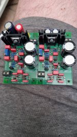
Modding RNHP for power on/off protection

Hi all! Owner of an RNHP (Rupert Neve Headphone Amplifier) here. The amp is known to generate significant noise/current from capacitor charge/discharge during power up and power down which passes loud noise and likely DC straight to the headphones. Neve advises unplugging headphones every time the unit is powered on or off, but my home studio is somewhat automated and the RNHP is in a rack out of reach. I also feel like an amp at this price point shouldn't require the user to disconnect and reconnect sensitive headphones before power on/off to avoid damage.

I thought I could just put the headphone plug on relays I could automate to switch in and out, but this apparently isn't functionally the same as disconnecting the plug for some reason. I've detailed below.

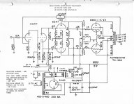
I feel like headphone protection is relatively underdiscussed and I'm trying to use this as a learning opportunity. I'm wondering if anyone with more electrical engineering knowledge than I have can weigh in on the feasibility of these ideas or others. There is significant information available about the design and circuits in this thread.

Here are some of the ideas I've tried:
  • Connect each of the 3 headphone conductors to their own 2-way relay. Open relays during power on/off and close the relays after a delay.
    • This seems to me like an automatable way to "unplug" and "replug" the headphones without literally having to do it.
    • All of my experiments with this yield an explosive pop sound when I switch in the headphones the first time after power on, presumably due to the current accumulating somewhere in the circuit and then being released into the headphones all at once
    • I'm not sure if there's a solution to be had here with a 2-way relay and capacitors to drain or shunt the current but I haven't had success with my attempts.
    • Any signal degradation from the relays? Not sure how to pick the right ones for headphone audio signals
  • Disconnect headphone plug from jack. Power up. Connect headphones. Disconnect them again before powering off.
    • Inconvenient, but it seems to work PERFECTLY.
    • This doesn't produce ANY noise upon connection of the headphones. Why does this work when my relay solution doesn't? I'd think they're functionally identical.
  • Adapt headphone output from RNHP and headphone plug conductors to BNC. Use a logic-controlled video editing router to switch the headphones in and out.
    • This works perfectly with no explosive pop sound upon switching, but ONLY if I engage the 75 ohm termination switches on the router.
    • I am not sure why this matters. Any ideas?
    • Don't know how to measure the signal path in the editing router to assess sound quality
  • Utilize an inline headphone protection circuit such as the E12 muting/protection circuit
    • Presumably a circuit like this would handle whatever current is generated during power on/off without sending it to headphones
    • I can't seem to find any prebuilt solutions for this
    • Not sure if this adds components to the signal path which I feel like isn't necessary
  • Modify a speaker protection circuit like this one for use with headphones
    • Perhaps switching it in and out via 2-way relays so it is not inline?
I know there are various elements of this problem I'm not understanding fully, so please feel free to correct anything I'm not getting.

I'll endeavor to post any updates from my ongoing testing.

Thanks,

MI

Any free PC software for using a Convolver (Mac or Windows)

Hi folks ..

I am new to this space .. I have an Arcam AV40 with Dirac, which works great with my basement. It is simply awesome and I have received lots of compliments from all my friends.

Now I also have a PA system (JBL EON 208) .. it is a nice two-speaker system with an Active mixer. I would like to use some Convolver or Room Correction when we use it in the basement for the Karaoke system.

So the question is what is the cheapest way to use freeware, to be able to perform room correction before it hits JBL EON.

So which software to use so the output from the Laptop is passed through the Convolver

Any advice is appreciated

my miniSET.UL

kt88.jpg


The whole idea is to make a mini tube amp that's everyone can built for their office/bedroom. :santa2:

Highlights:
-Open schematics
-Low component count
-Very affordable
-Extremely easy to build
-Sounds great
-Solid, Sexy & Sleek
-Wife friendly

Topology: SET Ultra Linear
Signal Tube: 6J8P <-very affordable
Power Tube: KT88 <-decent price
Power: 2 x 6.5W

Feature:
-2 pairs selectable stereo input
-Balanced XLR & Phono Headphone output (Wires Tap from the speaker output)
-4ohm/8ohm
-Bluetooth PCM5102/ES9023 in future*.

Built:
-strictly no "audiophiles parts" in the built


Things that are still under optimizing:
-slight of 50hz/100hz humming when the ear is put 2cm next to the speaker drivers, not ideal for headphone users. Still figuring a way to remove to hum without rectifying the 6.3Vac. Planning to lift the heater voltage referencing to a common that is far above the cathode voltage.
-Very limited bandwidth to 15khz@-3dB although one can hear sparkling and vivid highs from this amp.
-PCB Layout needed to optimized for easier installation and better layout.
-Chassis need a handle

The whole amp is functioning and the sound is surprisingly really very nice, spacious, great soundstage, sparkling high, fluidy mid, and i believe it can sound better than many of the commercial solid-state power amp out there easily. (I know everybody claim the things that born out from their hands are the best. 🤣 ) But its really good, the schematics is in this post and you might want to try it out.

I'm still figuring and compiling any possible way to further improve the performance and outlook, any suggestion is much appreciated.:wave2:

A bit progress here:
tube3.jpg

CNC cut on a ready made waterproof aluminium enclosure

tube2.jpg

laser cut bottom faceplate with gold anodizing and black rubber feets.

tube1.jpg

And older model with high gloss black powder coat.

tube5.jpg

Bottom PCB, with chokes, connectors and SMD components on it.

tube4.jpg

Top PCB, with Tube mounting on it.


PS: I don't wish that there is anyone taking this out for commercial purposes.

Attachments

  • ULSET.jpg
    ULSET.jpg
    316 KB · Views: 254
  • Like
Reactions: bondini

Q: Prototype Build - Routing Ground and Other Assembly Considerations

Hi,

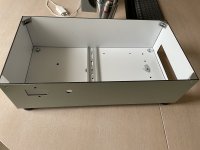
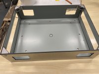
I'm going to test a new vacuum tube amp build, and would like to avoid problems with 50Hz and HF noise I had in the past. Power supply and amp prototype will be housed in separate boxes made with 3mm thick Neobond (porous plastic with 0.5mm aluminum on both sides). Neobond is surprisingly light and sturdy, is easy to process (mill, drill, etc.). Aluminium foil on both sides will serve as EM shielding. Foil on outer side remain intact, yet on inner is being cut with V-mill in order to bend sheet into a box. So where necessary I scraped coating in order to restore conductivity (e.g. on corners with aluminum brackets of 2020 type, DIN rail mount, etc.).
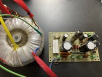
Power supply is assembled on prototyping PCB, stacked type 2xHV (220V toroidal transformer, secondary 2x159V, plus additional 42V/35V for adjusting output voltage, 60V BIAS, 3x6.3V filament). PS output terminals will be DIN rail splice quick connect type.
Since toroidal transformer supports up to 8A on each 6.3V tap, and will power up only 1 channel, I plan to power all vacuum tubes from single 6.3V tap.
For safety reason amp PCB will be mounted on additional riser plastic plate, not on the bottom of the box directly (further away from metallized surface).

Now the question: how do you recommend to make routing between these parts of the whole assembly: 220V power line ground, power transformer Faraday shield, power supply chassis, amplifier chassis, BIAS GND, amplifier GND, filament artificial middle tap (from 2 x 100...200 Ohm resistors). IMHO HV power and BIAS GND must be connected near terminal of PS PCB board (or may be amp PCB?).

Photos of some parts attached. Amp itself is on early assembly stage so there is nothing to show right now.

Thanks in advance for any help.

Attachments

  • 1.jpg
    1.jpg
    571.4 KB · Views: 113
  • 2.jpg
    2.jpg
    369.7 KB · Views: 107
  • 3.jpg
    3.jpg
    276.1 KB · Views: 100

Fidelity Research FR-101

Hi there,

I've owned the above cartridge for a few years now, used with a Rega Planar 2 with the early Acos style 'S' shaped tonearm - the so called RB-200.

I've been lucky enough to win an eBay auction for an NOS stylus for it. However, I note that it's an FR101-SE stylus. The -SE suffix is on the name plate on the stylus. The original doesn't have this - it's a plain old FR-101.

I know it's a long shot, but does anyone know what the difference is between the -SE and non-SE stylus? Obviously it must be a better 'special equipment' spec. but I can't find out anything. I'm supposing it's an elliptical versus conical diamond or something, but info. is a bit scant.

I guess reading Japanese might help on the net relating to this brand.

Cheers people.

Stuey

New 60W Williamson build choices

I've been looking at the 2 attached schematics as well as this video outlining something similar:

Login to view embedded media
I'm curious what everyone's thoughts are on a new build with either of these 2 designs. I'm favouring the UTC one as it seems more mature and has fixed bias.

I'd be leaving out some things as well like b+ to preamp, any input capacitors inline with the grids of the first stage, and likely establish bias voltage in a simpler way than is shown using the 6.3v from the filament windings.

I'd likely use all hammond iron for the sake of cost and availability. Something in the 1650 range for the output. I'd likely over-spec everything too in terms of size and current. I'd likely be using KT88's as well since they offer the most power and I have a stash on hand.

Fools errand or shows promise?

Attachments

C'est Compliqué - Broskie Hybrid Tube Circlotron

John Broskie posted, many years ago, a hybrid circlotron topology on tubecad. The interesting points about this design is it's a DC coupled tube-mosfet with dual feedback loops - one for the signal and a DC only loop.

Recently with an almost dead SS amp I was thinking if the fets were dead that a small hybrid would also fit quite nicely into the same chassis. Unfortunately all the fets survived and the amp is being recapped and tuned up. However the concept of using ECX10N20 which would have replaced the BUZ900P/905Ps with heavy biasing to operate in class AB got me thinking of updating the Cest Complique amp I have shelved whilst the world decided what it's going todo next. The beauty is that this is almost a roadkill style of build for me - salvaging or temporarily using components I have from various projects. Using smaller mains transformers is cheaper than a custom build HV transformer for a large number of tubes with complex heater-cathode requirements. So this is in modelling/design atm.

So my target is a class A hybrid circlotron able to support 8-55 ohm loads.

Screenshot 2022-05-19 at 06.22.27.png


This is the power section, the 12BH7As provide a driver for the ECX10N20 that provides the grunt and finally the ECX10P20 provides DC offset control. The bias of the 12BH7A is about 9mA and the bias of ECX10N20 is a hefty 554mA currently. The idea was that the 12BH7A can take a 5Vpp input signal, although currently the system is running about -7Vg operating point at the 9mA.
I could spout THD/noise from LTSpice but the reality is I'll wait to see what the real components show. LTSpice shows 0.07% THD as it stands but there's still lots of design work and a front end required to add some character. The output, as you'd expect with a circlotron, is 3rd dominant but that's quite low.

With a 2Vpp input it's putting out 240mApp. So that's more than enough to destroy headphones.

Screenshot 2022-05-18 at 18.47.38.png


I put the current into the FFT as I can't work out how to get LTSpice todo FFT if a maths expression, not sure if that's correct but it seems about right. Either way with a tube frontend that's likely to be completely irrelevant 😀

I've tried to compensate for the phase shifts by testing using a VO in one feedback loop rather than putting a second VO in the opposite side. Essentially I've split the bridging and tested/tuned one half and then replicating the changes to the other side. The DC low pass for the DC P-channel is tuned to 1.4Hz. I figured most headphones at that point would be heating too much so that's as accurate as it needs to be.

With 2Vpp input the response phase looks like this for either side:
Screenshot 2022-05-19 at 07.06.36.png


I hope I have this right in using V(outB)-V(outA) but the resulting nyquist looks stable.

PS. Ignore the unity gain in the filename..
  • Like
Reactions: decramer

Distance between two class D output filter coil

Hi all

May I ask a noob question?

I am now building 2 channel classD amplifier and trying to layout the chassis with this 2 channel amp inside.

My question is,
Is it ok to place the output filter coil close to each other. Do they have EMI noise coming out and induce to other channel? Is the rule of speaker crossover network coil also apply to class D output coil, ex. we should place the in different direction?

Thank you for the comment.
Tanwa

Myyyyyyy SPL-GORILLA 2400 in the Car Audio Forum

GREETINGS Car Audio Forum, I posted this situation in the CLASS D section but thus far only an idiot responded in regards to my WRITING STYLE?...... My goodness.

WELL... I thought to post here too and see if anybody here in CAR AUDIO has some INTELLIGENT POSITIVE input. I bought a GORILLA 2400 watt Class D MOMO SUBWOOFER amp for 10 bucks, it had a blown POWER TRANSISTOR so I ordered another. Upon examination i discovered another POWER TRANSISTOR was REPLACED by someone else. SO.... THIS AMP is like brand new, spotless DUSTLESS.... I BELIEVE it was a WARRANTY repair right out of the BOX that FAILED YET AGAIN SO.... that customer got a BRAND NEW amp and this one got tossed in the PILE. I bought it on EBAY so I am unsure of its history except that it was obvious there was a replaced transistor and a blown/shorted one when it arrived here in Hawaii. I bought new transistor and did all the testing to see if this thing was losher and it WORKS.

Ran for 4 hours straight. ONLY ISSUE I notice now is the DRIVER BOARD, it appears to be running HOT.... not warm. Pretty hot. I notice several transistors in there that are HOTTER than the others, theres a group of 10 or so transistors on the board and they are grouped together BUT as I finger each I can feel some are MUCH hotter than some of the other transistors SO......

Perhaps the DRIVER BOARD is the main culprit. I ran the amp at idle 4 hours and its still operating fine. Just a HOT driver board situation. Here's my FEAR... Once INSTALLED in a CAR and RUN HARD I am gathering them driver transistors will get even HOTTER... Hmmmmmmmm........ Perhaps they are running FULL ON as they are designed to drive other transistors THUS they will run hot at IDLE as well as FULL OUTPUT without any difference.

The POWER TRANSISTORS thus far have NOT heated up at all. Need to run it harder I suppose. I did notice the TRANSFORMER was a bit warm but I believe thats normal.

OK..... Someone chime in with GOOD NEWS... Class D driver boards run HOT by design and I am NOT having a secondary ISSUE that will eventually lead to a THIRD transistor needing replacement as well as the DRIVER board.

I am very HAPPY that I managed to get this 10 dolla BEAST to come back to life. I would like to actually USE this amp though. SO it MUST be "fixed" properly and never blow under normal conditions as well as some extreme conditions, occasionally.

THANKS for any positive input here, i am a novice and this is my firat Class D amp foray.

MAHALO and ALOHA from Hawaii..... BDBD/2022

Repairing fairly rare mosfet amplifier, things to double check?

Hello all, my father picked up a rare amp/preamp combo, that amp is a Superphon Maxx 806 (or 80b) made right down the road from me in Eugene, Oregon by Stan Warren of PS Audio. Two of the N channel fets in the right channel had exploded prior to him buying it. I ended up replacing all of the mosfets with IRF520/IRFP520 devices and replaced all of the capacitors, increasing the filtering from 20,000 per rail to 30,000. I checked all of the balancing resisors and other transistors in the circuit prior to the outputs and all was good. Guessing maybe the output was shorted????

Powered it up and it was great for about 5 minutes and then I turned it off. I’m not super familiar with fet amps, BJT mostly. There is a small trimmer in each channel and looking at the paint they are in the factory positions. Should I leave it and run it as is? Should I make an attempt at setting bias? Unfortunately without any schematic or service manual I’m kind of lost as far as what I should do with it. Seems stable as is, but would love some guidance. Thank you.

A682D679-84C6-428F-A09D-94CE1CCD6D03.jpeg

9438BED7-DF68-4A1A-A6B1-B32CC2C32317.jpeg

02B93EDB-C228-4F8A-9B27-C660340BA22C.jpeg


Dan

Garage sale drivers

EDIT
I wish we could edit titles
That should read GARAGE sale, although garbage might also be appropriate sometimes

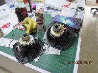
So today I went to a heavily advertised garage sale and bought some cheap woofers.
One of them is unfortunately open circuit but that is the risk you take when you forget your multimeter.
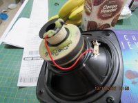
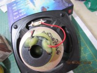
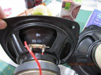
But I thought the 2 small woofers were worth $10- because somebody had hot glued a coli to the back of each and the coils are worth a couple of bucks each.
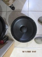
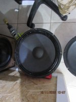
The generic 15" is about what I thought it would be, 30Hz Fs and a Qts of 1.1 but I can do something with it.
Seller also had some cheap Jaycar 8" woofers but only 3 of them and you need 4 of these for any decent OB design
Anybody recognise the small woofer?
Fs is 50Hz and Qts is about .8 Might be usable in a party box
Maybe I can learn how to replace voice coils using the cheap open circuit driver as a learning tool or just screw it to a sheet of ply and use it as a magnet vice

Attachments

  • IMG_2408.JPG
    IMG_2408.JPG
    84.2 KB · Views: 109
  • IMG_2409.JPG
    IMG_2409.JPG
    76 KB · Views: 106
  • IMG_2410.JPG
    IMG_2410.JPG
    96.1 KB · Views: 100
  • IMG_2411.JPG
    IMG_2411.JPG
    74.8 KB · Views: 101
  • IMG_2412.JPG
    IMG_2412.JPG
    45.2 KB · Views: 102
  • IMG_2413.JPG
    IMG_2413.JPG
    47.1 KB · Views: 102

Suggestion of capacitor type across transformer, Fender twin reverb 65 reissue

Hey guys,
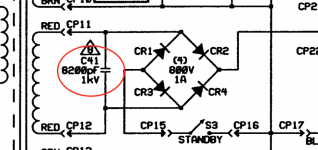
I've got a fender twin reverb 65 reissue which came in for repair (for recapping basically) after another tech have installed the main transformer (was designed for 120V now fitted with the 230V transformer. I'm trying to get fuses etc into spec and according to the service manual there needs to be a 8200pF 1kV capacitor across the main winding of the secondary side if the amp is to be used with 230V mains. The manual does not say what type of capacitor it should be.
I was hoping someone can direct me. Should it be an X2 type cap?
Thanks

Attachments

  • Screen Shot 2022-11-19 at 3.05.55 AM.png
    Screen Shot 2022-11-19 at 3.05.55 AM.png
    30.7 KB · Views: 86

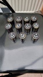
Is there a maximum multi-Farad capacitor cycle?

For a power amplifier I am contemplating a multi-Farad buffer to the power rails. That would complement some aplifiers great That now also have 56.000 uF big-can capacitors like from Mallory, big, blue, screw Mount. Some designs just love such buffers!

While I can easily cycle the power supply to an on-state = going from 0 volt to 14 volt, I am worried that the capacitors might not ‘like’ that and are in fact made fo allways-on use.
Such as being used parallel to a (car) battery. Then it virtually never goes ‘off’ to unloaded.

On the other hand, in an amplifier I would see it stop gracefully in about 5 minutes, once the power is switched off.

So in actual use it would cycle.
If that is is not wished, then I would make a relais (the DC-type contacts as used in cars) to engage them. Then they would stay charged When the amp is not in use.
What is your advice for this?


Supercapacitor Retificador Automotivo 2.7v500f 16v83f, Módulo De Condensator Super Farad Para Janela Automotiva

Greetings from Dutchman

Hi everyone, totally forgot to introduce myself yesterday, sorry! I only just now found out this section of the forums exists 😀 I love music and I love a good bargain. I've always bought my equipment second hand. I guess I'm truly dutch in that way.

My setup consists of a 70's or 80's amp (at the moment a failing Mitsu DA-U200), Loewe Konzertbox LO26, 2 Technics turntables (SL-D2 & SL-D3) and some other peripherals.

What I wrote yesterday in my first post in Solid State was meant as an introduction:

"After some weeks struggling by myself I found it's time to ask for some help. Luckily I found this very alive forum full of audiophiles like myself! I'm a newbie in DIY repair. I'm giving it a shot on a Mitsibishi DA-U200 amp. It's not rational to put so much time in an old amp, it's purely because of the sentimental value. And I love the warm sound of the late 70's / early 80's amps. My backup amp is a 90's Yamaha Natural Sound (AX-470). And that sounds so flat to me after all those years of warm sound!"

Will keep you posted in the thread about my struggles to repair the Mitsu.

Cheers!

Question re paralleled tda1541a chip

Hello,

I’ve seen talk about paralling or stacked tda1541 chip for a dac but it was not clear to me if any other changes are needed.

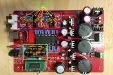
Basically, i’ve built a Dac based on this chip using the board in the attached pic and using a tube output stage based on lampizator circuit using 6n2p tubes. I’m very happy with the sound especially for the type of music i listen to. I’d say it’s definitelly not a setup for all genre of music.

Coming across a second tda1541 chip, i’d like to try and stack them on top of each other with some sort of aluminum bar in between for heat dissipation. Have seen it done here by a few members but as stated before, it’s not clear if any other changes are needed to decoupling caps or any other dac pins. The power is plenty.

Do i simply just solder them on top of each other? I undersatnd that i have to halve the i/v resistor if i use 2 of them.

Thanks

Attachments

  • 7617BD21-5370-4D0F-A16D-81D3D6929BAC.jpeg
    7617BD21-5370-4D0F-A16D-81D3D6929BAC.jpeg
    546.7 KB · Views: 127

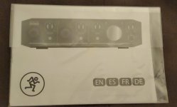
For Sale Mackie Onyx Artist 1-2 USB Audio Interface

I was going to try to use it to digitize some vinyl and see an FFT on my computer. I don't know if it can accomplish that and I never got around to it.

$60 including US shipping (goes for $90 on sale at sweetwater.com)

Never used. Package was opened solely for the purpose of the photographs.

Combining high-resolution 24-bit/192kHz converters with Mackie analog circuitry and Built-Like-A-Tank hardware design, the bus-powered Onyx Artist 12 is perfect for singer-songwriters, content creators, and mobile recording. The Artist 12 features an Onyx mic pre with phantom power and a ¼” line input with Hi-Z instrument switch for quick and easy recording. Plus, with zero-latency direct analog monitoring ensures you can always hear yourself in real time. With the Onyx Artist 12, you have the power to capture your performance and experience media with pristine fidelity at home or on the go. Your Creativity Without Limits – Onyx Series USB Audio Interfaces.

20221107_180622.jpg
20221107_180634.jpg
20221107_180701.jpg

FS: JC2 Preamp in Cambridge Audio chassis

Good day everyone.
For sale is JC2 preamplifier installed in to Cambridge Audio azur 340A chassis.
Been using this preamplifier for some time, till it been replaced with new one.
CA Remote control working for input selection and volume control.
Headphone amplifier working, all knobs are made from Ebony wood.
Location in UK.
Looking around £80.00 ONO.
Thank you.
image1 (2).jpeg
image0 (1).jpeg
image1.jpeg
  • Like
Reactions: yogiDIYbear

Some quick heatsink mounting questions

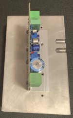
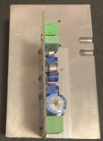
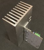
I got some ready-made JLH1969 modules, which came with a piece of aluminium L profile to be mounted to a heatsink. I found some heatsinks, that should be large enough and there are some threaded holes already. These would be perfect to fix the board exactly in the middle of the heatsink (2 holes fit). The heatsink will be placed upright, so I wonder if there was any benefit to placing the board as close to the bottom as possible - I would have to drill and tap one extra hole (see the pictures)

And my second question would be to the mounting of the L profile to the heatsink - if I am correct, I should sand and polish the matching surfaces and then apply just a little amount of heat conducting paste between them. Or should I skip the heat conducting paste if the surfaces are perfectly treated? Do I need a metal bar to press the L profile better or would just large washers do fine?

Attachments

  • C5065D69-E7DF-466E-BCBD-9ABE27F50B56.jpeg
    C5065D69-E7DF-466E-BCBD-9ABE27F50B56.jpeg
    278 KB · Views: 152
  • 5F877C52-593E-46D7-AF97-0C6F913DDD2A.jpeg
    5F877C52-593E-46D7-AF97-0C6F913DDD2A.jpeg
    313.3 KB · Views: 153
  • 2D387E85-7BAB-40F6-B21E-C791E7B0B3F6.jpeg
    2D387E85-7BAB-40F6-B21E-C791E7B0B3F6.jpeg
    482.8 KB · Views: 154

Bookshelf enclosure for the Lii Audio 6

Hello Brains trust
Recently acquired a pair of the Lii audio 15's and plan to open baffle them in due course. Due to the very, very slow delivery, Lii Audio also sent a pair of the 6 inch speakers as a 'sorry it took so long' for free! This gives me an opportunity to build another pair of speaker boxes, preferably of a bookshelf size (can do a max of 30cm wide, 30cm's deep, 50cm's high). I'm not good at design and from reading around the forum, the Lii's measured figures differ from what they actually achieve. They can obviously be smaller in size and I wonder if anyone has had experience with them already or could suggest a box that suits them nicely.
I thought about copying the silver 6 dimensions from their website, but there are no details about what's inside the box.
Amp is a little Yamaha desktop with about 15 watts and they'll be in a large space for background music at work.
All suggestions appreciated and thanks in advance, James

Looking for SS Phono Preamp

Hello everyone,

Atm, my system is as follows:

B&W 804 Matrix
Forté Audio Model 3
PS Audio 6.1
Arcam rPhono
Rega P3 w/ Goldring 1042

I'm looking to upgrade my phono preamp and was looking at spending as much as €1k for something like the Rega Aria. But going down the DIY path might achieve the same/better results for less. I'm looking for as much RIAA accuracy as possible (my Arcam is rated at 0.2db, so I'd like to get to the 0.1db camp), low noise floor and good shielding/grounding since I've had hum issues in the past. I need it to feel like a real upgrade if I'm spending the money.

I thought about tubes, but since one of my main goals is improving SNR, I don't think that's a good idea. And to keep it cheaper, SS is the way to go imo.

MM and MC could be an option, unless you guys tell me a step-up in the future might yield better results. What I need is a few gain and capacitance options for MM and a Mono button if possible.

Is there something that fits all of this given how much I'd like to spend? I know I said €1k for the Rega, but if I can achieve the same/better for as much as half, I'd be a happy man.

PS: I'd not be the one building it. It would be a skilled engineer I know, so even though kits could be a solution, schematics are green light too.

Let's hear it. Thank you!

For Sale First Watt Aleph J clone with dual power supply

First Watt Aleph-J clone for sale, made with a dual mono power supply. The case is from Modushop and the power supply is from the DIY Audio store (x2). The two oversized transformers make this a very heavy amp. The speaker connectors are rhodium plated models from GaoFei and are very heavy duty. Inrush current is limited by CL-60 inrush current limiters, which are bypassed after a minute or two by hospital-grade relays. Amphenol D-shell RCA connectors are used, which cannot come loose like ordinary RCA connectors sometimes can. Everything is in excellent condition; the only flaw is a small nick in the top of the front plate. This is an extremely reliable amp, practically bulletproof, with a nice sweet sound. Asking $975 + shipping.
DSC03716.JPG

DSC03709.JPG

DSC02448.JPG

DSC03719.JPG

DSC02433.JPG

DSC02444.JPG

DSC03712.JPG

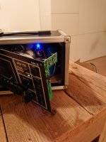
Making a boombox from an old portable DAN-SOUND tapedeck

Hi everyone, I'm not sure if Class D is the right subforum for this, so let me know if there's a better section on the site for this.

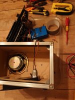
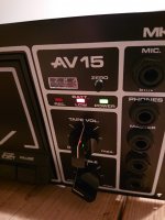
A while ago, I got this old portable tapedeck from work, the kind they used for learning languages at school and for the Cooper test at gymnastics in the 80's en 90's. This one was a DAN-SOUND AV-15. It was powered by 230V or 6x 1,5V batteries.

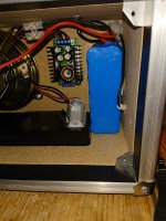
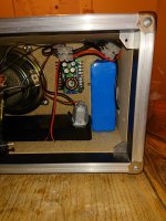
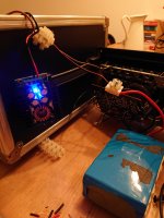
I also had this lithium battery lying around, which I intended to use in an electric scooter, but was the wrong voltage.

So I thought: why not combine both to make a great oldschool boombox? I did and it worked!

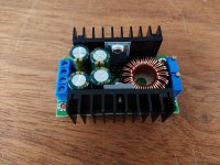
By using a step-down converter I created the necessary 12V to power the tapedeck and the amplifier itself. And by installing a car USB charger I can now connect a bluetooth transmitter and charge my phone. The USB adapter includes a voltmeter to see remaining battery power.

The disadvantage of this deck is that it has only one woofer, so only mono sound. The sound quality is poor overall, lot of hiss. And no high frequencies. I'm planning to attach cheap old portable stereo mini speakers which run on 4,5V battery power. Just to add some stereo sound & more high frequencies.

It has been a fun project so far. I'm certainly not planning to create a perfect sounding machine out of this.

 Warning: working with 24V DC lithium batteries can cause a lethal electrical shock. Take appropriate safety measures.

Attachments

  • DSC_1048.JPG
    DSC_1048.JPG
    310.6 KB · Views: 101
  • DSC_1046.JPG
    DSC_1046.JPG
    364.2 KB · Views: 90
  • DSC_1042.JPG
    DSC_1042.JPG
    451.1 KB · Views: 102
  • DSC_1041.JPG
    DSC_1041.JPG
    542.3 KB · Views: 94
  • DSC_1039.JPG
    DSC_1039.JPG
    384.8 KB · Views: 90
  • DSC_1033.JPG
    DSC_1033.JPG
    460.3 KB · Views: 98
  • DSC_1016.JPG
    DSC_1016.JPG
    487 KB · Views: 90
  • DSC_1014.JPG
    DSC_1014.JPG
    310.2 KB · Views: 88

Twisted Sounds TS3.5KW Advice.

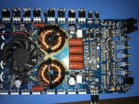
I need advice on a Twisted Sounds 3.5K.

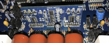
The amp came in with the following damage:
  • Power Supply(PS) MOSFETs failed
  • PS gate resistors failed
  • One bank of PS drivers leaking
  • Rail Capacitors failed
  • One section of the audio output failed
  • Audio MOSFET Driver Transistors seemed to be leaky on failed section. Uses KTA1715 and KTC2814 drivers

The PS section was repaired, defective audio section MOSFETs removed, but the amp will not run without shutting down the remaining audio section. This was accomplished by pulling pin 2 on the IRS21844S low.

With the audio section disabled I was able to verify the following:
  • Rail voltages as expected, +110V and -110V. (For others, I believe this amp uses transformers in series)
  • The +15V and -15V regulators are working as expected and all opamps on the main board had +-15V
  • The 12V (above the negative rail) is produced by a transistor boosted zener circuit and is working as expected. Output is 11.6V on the emitter
  • Audio signal is reaching pin 5 (center header) on the class D PCB maximum of about 10V p-p
  • The ZNCM_HP V10 board is used
  • There are no obvious shorts on the IRS21844S drivers, when testing the two LO and HO.
  • I do see some input close to the negative rail on pin 1 of the IRS21844S drivers.

I am sure this is a generic design. Does anyone have a schematic diagram that may be close?

What is the next steps in this repair? It seems that everyone suggest just replacing the 21844 drivers, even if I cannot determine definitively that they have failed.

Thanks All for the help!

Attachments

  • IMG_2930.jpg
    IMG_2930.jpg
    750.7 KB · Views: 446
  • IMG_2892_C.jpg
    IMG_2892_C.jpg
    580.6 KB · Views: 366
  • IMG_2893.jpg
    IMG_2893.jpg
    1 MB · Views: 432

3FE25 UTP Cat 5 star quad - speaker cable

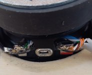
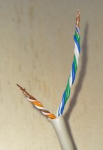
I changed the wiring of the MDD3ZC350 prototype using UTP category 5 network cable. The orange, orange-white, brown, brown-white wires are in parallel in the positive pole. In the negative pole the green, green-white, blue, blue-white wires are in parallel. The twisted pairs are diagonally in a star quad configuration.

The positive pole wires are 25 mm shorter than the negative pole wires which pass behind the spoke of the 3FE25 driver's steel basket. Care must be taken to maintain at least one mm of distance between the spider and the negative pole which passes behind the spoke of the basket. Both poles are soldered directly onto the driver terminals and the couple of meters long lead goes directly to the amplifier with 4mm banana plugs.

Listening to it I noticed an improvement which however could be due to the elimination of the crack in the left channel flange. It is a simple wiring to make, very cheap and effective in minimizing electromagnetic disturbances, I will also use it in the next prototypes.

In recent years I have documented the optimal RLC parameters that the cable connecting the speakers should have. My conclusion is that since these are linear parameters they cannot degrade the quality of the reproduced sound. There are many simple and inexpensive techniques that reduce the three parameters to levels suitable for a home system. With capacitances and inductances that are too high, the frequency response is affected above all.

This wiring has a capacitance of approximately 100 pF/m and keeps the inductance at low levels (reduces the magnetic field emitted). The reduced section of the cables is not a limitation in this case, with the 3FE25 driver from Faital-Pro with one watt it exceeds 90 dB at one meter. Going further can disturb family members, neighbors and even your own ears as the driver starts generating distortion.

The main advantage of this wiring is the particular geometry which reduces the effect of electromagnetic interactions. In particular, it reduces the emissions of the cable itself which can generate non-linear phenomena by interacting with the driver and the amplifier. In star quad wiring, for each circuit that generates a magnetic field, there is a second that generates a magnetic field of opposite sign at a distance of a few millimetres. The elimination of the connectors avoids having surfaces of a few square centimeters capable of emitting magnetic fields. Passing the negative pole wire behind the spoke of the driver basket avoids inserting ferromagnetic material into the circuit.

Star quad cabling with a single UTP cat 5 cable can be used for powers up to about ten watts, with an impedance of 8 Ohm the electric current remains less than an ampere. The low capacitance makes it suitable even with low power amplifiers.

The proximity of conductors forming four circuits in opposite orientations reduces total inductance and minimizes interaction with ferromagnetic material in the vicinity of the speaker wire. Each ferromagnetic object greatly increases the magnetic field in the area in which it is located and also the magnetic flux chained in nearby circuits. The effect is more pronounced if ferromagnetic material is inside the circuit. In the case of the radius of the drive basket with the standard connection a non-linear component is created in the inductance of the circuit, when listening at low volume or in the car it does not create problems, if you listen to a flac song with a quality system you can perceive the distortion.

Thanks for your attention.

links:
https://www.claudiogandolfi.it
https://www.claudiogandolfi.it/662g.html

Attachments

  • c504.jpg
    c504.jpg
    133.5 KB · Views: 111
  • c501.jpg
    c501.jpg
    60.6 KB · Views: 115

Single 6N6P preamplifier has no bass to speak of...

I have a 6N6P 2 channel preamplifier that uses a single 6N6P tube it does work but the bass is virtually non existent.
and it has no tube warmth.
I suspect a too low bias point as I have already tried to find many possible causes for this.
The tube runs at 122 V on the Anode B+ is 162 V
Anode resistor is 5k12 voltage drop is 40V so current is 7mA
Cathode resistor is 565 Ohm voltage on Cathode is 4.4 V
Input impedance is 47k Ohm
Output capacitor is 1µF load is 40k Ohm it is a transformer.
Can someone please help me make this thing sing?
Thanks!

Digital recording artifacts

I'm having a hard time making acceptable quality digital recordings of an 8-bit computer synthesizer - that is with the line-out of the synth plugged into the line-in on my soundcard. The voices of the synth are programmable-frequency square wave generators.

Max level is 8-10 dB below clipping on record, but single discrete notes that sound pure directly from the synth acquire an annoying degree of "graininess" when recorded and played back - like there is a lot of FM modulation.

When playing chords of closely spaced keys in the same octave, additional and distinctly annoying artifacts are produced. It's present on the initial uncompressed WAV recordings but is exacerbated when the recording is compressed, which you can't avoid when uploading to a video sharing site.

The chord playing artifacts (especially after compression) make the digitally recorded audio sound remarkably like something being played back from a scratchy LP record.

The synth analog out has a single-pole roll-off at around 18 kHz. There is no undue noise or anything else.

I am wondering if there is still enough high-energy harmonic content in the squarewaves to play havoc with my audio cards digital sampling. My card is a not too flash Asus "Xonar" thing that set me back in the region of $35 maybe 10 years ago.

Has anyone else had similar experience or has enough insight into the robustness of anti-aliasing filtering on run-of-the-mill soundcards?

Acoustic 260 amp shorted outputs??

Trying to bring a Acoustic 260 head back to life.
Had a blown fuse, replaced fuse and plugged it using my light bulb series power tester, bulb
stays fully lit.

Pull all four of the output transistors, easy to do as they are plug in socket mounted, short
is gone, bulb briefly lights bright and fades down to barely glowing.

Using a multimeter in diode test mode all transistors show they should be good.
Checked the two driver transistors the same way and they check good as well.

Output transistors are 40411 NPN RCA's

Anyone else dove into one these, schematics seem to be non existent,

Would it be worth just replacing the outputs with something like a set of MJ15024 or 2N3773 transistors and see
where that takes me?

Mike C.

EL 84 SE 5K Output Transformer

Hi,
I have a class a se amp project with EL84 tube. But I can't find output transformer in my country. I am looking for the winding technical information of the transformer with technical data below.
-Primary part wire cross-section and number of turns.
-Secondary part wire cross-section and number of turns.
I'm sorry, my English is not very good.

Primary impedance : 5K
Secondary impedance : 0 - 4 - 8 ohm
frequency response : 20Hz ~ 40KHz
output power : 8 ~10 watt

Topping Preamp pre90

Hi I just purchase Topping Pre90 and connected to ML 5302 using both XLR input from my DAC and XLR output to amp. I double check the connection, turn the power on Pre90 and turn the power on ML 5302 and almost blow up my speaker. Luckily protection circuit was kick in and disconnecting save my speakers. Any idea what is going on?
The DAC was off and there is no source signal. Pre90 volume was set at safe level -40 dB. Defective units? I purchased the Pre90 because of such good reviews but very disappointed. Thanks
  • Like
Reactions: Rewind

Split pair of channels in stereo head

Hi
I am looking to add another pair of outputs to an old car stereo head, so there are 6 instead of 4 (pre-amp level) channels out, all with the same output level.

So - I am looking to take one of those stereo pairs and duplicate them, with the resulting pairs being the same output level as the single outputs with some sort of buffer amplifiers (so I have three stereo pairs coming from the amp, albeit with two of those tied together on the fader control).

This is presumably a basic generic circuit - but I can't find quite what I'm looking for on the web, or the name this sort of circuit goes by (buffered splitter?).

I don't know what the exact output levels coming from the stereo head pre-amp channels are, but they must be within standard range because it works ok on several different car amps.

Making a circuit board is no problem, but I am after some advice on the right design for this purpose. Or else perhaps there is a cheap Ali-express unit which does this job for pennys (what would that item be called?) - though I am happy to make my own DIY board.

Thanks

Help please, powering up a pair of huge diy amps .

Hi guys,
First of all I should mention that I’m not in the league of many of you , I’ve changed a few capacitors and upgraded cables on amps and speakers , I now have these huge power amps which I believe haven’t been switched on for about 10 years, I wish to power them up myself but can this only be done safely with a variac ? And if so how do I know how many amps the variac needs to be etc . They are 240v and I’m told are 1000w ( output) each .
Obviously I don’t want to simply plug them in and hope for the best so what’s the best plan of action please?
3683048A-1B88-4D74-B011-298E263D226A.jpeg
DC9DB6F3-E358-44DB-9951-01832730364E.jpeg

Adding fonts in QuickPanel

I'm playing with both QuickPanel and Front Panel Designer, seeing how the prices and software compare. I find the instant online quotes pretty impressive. Schaeffer appear to be more expensive but the software is better in my opinion.
Quickpanel only has one font loaded in.
Is there an easy way to load in the fonts we would find in our computers in Windows for instance .? The tutorial on adding text which I assume is maybe a vector type is way beyond my pay grade.!

.

Looking for plans for a Tapped sub

I used to have a pair of DTS10 subs in my last HT (which I loved), but I sold them when I moved...plus they would be too big for my current location. I am looking for a design for a tapped sub that is 3' wide, 2-3' tall, and 2' deep. I would like it to go flat 40-60Hz down to 20hz (corner loaded with concrete floors, and walls), and prefer an inexpensive woofer (woofer prices have skyrocketed in the past 5 years). The sub will go under my K402MEH horns...hence the dimensions I listed. I would like it to be able to put out about 120db @1 meter and will be powered by a Icepower 125asx BTL amp module.

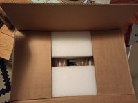
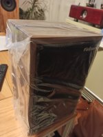
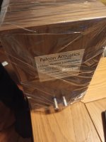
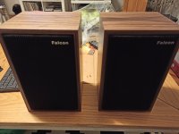
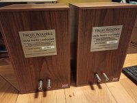
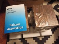
Falcon acoustics Silver Badge LS3/5A

New loudspeakers - unpacked, tried and returned to the box.
Walnut finish.
They sound sublime.
Price would be 2100EUR.

Attachments

  • IMG_20221107_222020.jpg
    IMG_20221107_222020.jpg
    358.9 KB · Views: 108
  • IMG_20221107_222141.jpg
    IMG_20221107_222141.jpg
    345.5 KB · Views: 115
  • IMG_20221107_222200.jpg
    IMG_20221107_222200.jpg
    271.2 KB · Views: 102
  • IMG_20221107_222207.jpg
    IMG_20221107_222207.jpg
    273.8 KB · Views: 114
  • IMG_20221107_222529.jpg
    IMG_20221107_222529.jpg
    315.9 KB · Views: 115
  • IMG_20221107_222541.jpg
    IMG_20221107_222541.jpg
    419.2 KB · Views: 110

old PSPICE files

I have an old PSPICE schematic that I would like to plot. I went to Orcad and started the process of downloading the "free" version, but it seems they want to sell you a complete CAD system. You have to send a request, get an email, ... It's not really worth it for me. If I could run an old version, that would be fine, and just PSPICE, no CAD stuff. I have mostly repeated my work in LTC spice, so the need for a PSPICE viewer diminishes. But I would still like a small simple file viewer. Any suggestions?

Can you use active crossover to help design passive crossover?

Hi

Im doing a my first "real" 2-way speaker design, i have have dabbled before with few designs but this time will do it correctly taking time, measuring, building foamcore prototypes and modeling with vituixcad.

Thing is that i am wondering, is could active crossover help with design? (My midwoofer is Audio Technology 18H52)
I would need to try few crossover points to find out which could work out best for my taste, like 1600hz, 2200hz, 3000hz, 3400hz etc..
(with particular tweeter im testing)


Active could help out making this easy to try what i like, so i will know what crossover point i will take when i start modeling, right?

Class A board DOA33. PSU Help!

Hi Guys,

I bought this Class A board. The auction states 28v is ok. On the board itself it says 33v +-

The auction also states 30va is good enough. So I bought a 50va 25v stuck it in the 6a (I think) bridge rectifier and got out 56v.

I presume this is 56v +- so I stuck it in the 33+- and got a loud buzzing.

I'm probably doing a thousand things wrong!

Thanks in advance!

Attachments

  • IMG_20190502_001316733.jpg
    IMG_20190502_001316733.jpg
    354.8 KB · Views: 328
  • IMG_20190502_001301652.jpg
    IMG_20190502_001301652.jpg
    378.1 KB · Views: 331
  • IMG_20190502_001338138.jpg
    IMG_20190502_001338138.jpg
    279.8 KB · Views: 329

Biketronics Amps and Fuse sizing?

What are the recommended fuses to be used for each of these Amps to make MAX power and what are you getting with the fuse amperage you are using?

BT2180 = 2 x 180w UcD OEMLP modules
BT4180 = 4 x 180w UcD OEMLP modules
BT2250 = 2 x 250w UcD OEMLP modules
BT4250 = 4 x 250w UcD OEMLP modules
BT6180 = 6 x 180w UcD OEMLP modules
BT2700-2 = 2 x 700w UcD OEMLP modules

New to valves/ tubes. cant seem to get this to work

Hello all

So I have been playing with this amp for a bit and reading the fourth edition of Valve Amplifiers. I have finally gotten the output to be a decent voltage without distortion. However I am running into the issue that lower frequencies really drop in voltage and the higher frequencies spike. cant seem to figure out how to address this, any advice will be appreciated, if my design sucks, please tell me.

Attachments

Looking for answers with Revel Ultima Studio

I am considering purchasing a set of Revels. The Ultimate Studio. Not the 2 version. Anybody have a pair out there?? Was listening to them in a dedicated showroom that was set up for listening. The speakers were on the short wall shooting down the length. Room was about12' wide by 18 long. I heard and also measured with FFT on phone a huge suckout at 40-50 hz. This was straddled by big peaks at 60hz and 30hz. Just wondering if anyone has in home measurements on this speaker? Saw a Stereophile review that show a shallow suckout at the same frequency about 2-3db. What I was measuring was about 20db!!

Troels Gravesen's Nomex 164 mkII

FS: Troels Gravesen's Nomex 164 mkII

SOLD


For sale a beautiful set of these really good sounding 2.5 ways towers!

New price request 500€ + shipping costs (to be defined, in case).

You can see the pictures of them at this dropbox folder link.

The items are in Italy (Florence), built by myself at the end of last year.
I'm selling them because I'm moving to a new house and there will not be enough space for them (at least this is my wife idea, and I had to follow her decision!).

They are well built and sound really good. Veneer is still to be applied, so you can choose the finish.

At this page you can find all the technical informations.

I can ship without problem, and I can ensure a solid and secure box; anyway, it will take me some time to prepare it and for sure the shipping will be a little expensive (not my fault, I will not ask anything for materials and labour).

Of course picking them in person after listening is more then welcome!

Waiting for your response,
best.
Giacomo!

NS1000 clone and or similar performing mid...

Hi,
I have a pair of NS1000m (s) but am aware that they are "old" with unobtainable parts. I love the dynamic midrange.

I perceive that the large magnet, and hard dome are the primary contributors to the efficiency and transparency.

Therefore in the 21st century, are there any drivers which offer similar performance, particularly embodying the qualities that I think the NS1000 mid excel at:

dynamics / transients
transparency
efficiency

My ongoing search for the perfect mid lead me to acquiring some ceramic magnet 5" Accutons, but they are not particularly efficient.

Budget: ideally less than £100 each, but flexible, current ish production.

I have multiple speaker projects on the go at present, mostly waiting for my time and workshop to be finished, (almost is!!!) so this is a slow moving request...

Thank you for humoring me in my quest for the perfect mid.


Current speaker projects for the curios:

Shackman based 2 way. Parts acquired.

Bozak homage, Bandor 2" and Monitor Audio 10" bass (active, current drive) in Goodmans Magnum box! parts aquired.

monster LX5... Linaeum tweeters, Accuton mid Kef B139 bass (4 per side). parts acquired.

Serviceable 3 way monitor / NS1000 clone. still in the thought phase.

Sending subwoofer signal to the main speakers

I'm experimenting with a bi-amping setup. The active crossover used is an a/d/s/ 642ix car electronic crossover. It has a feature that allows it to feed subwoofer signal, i.e. bass lower than 80 Hz filtered by subwoofer channel low-pass, to main speakers. The main speaker is a floor-standing type with two 10-inch woofers per side. The subwoofer signal would be set to MONO operation. My question is whether I need to use a "band-pass" filter on the woofers of the main speaker. Or can I use the main speaker as a full-range speaker? Because the subwoofer signal is set to mono and will be fed to the main speakers, I'm concerned that the stereo bass of the woofers and the mono bass of the subwoofer signal will interfere with each other.

System configuration:

(A) Run the main speaker as a full-range.
Tweeter = 5 k - 20 kHz
Midrange = 500 - 5 kHz
Woofer = 20 - 500 Hz
Subwoofer (fed to the woofer) = 20 - 80 Hz

(B) Apply a band-pass filter to the woofer.
Tweeter = 5 k - 20 kHz
Midrange = 500 - 5 kHz
Woofer = 80 - 500 Hz
Subwoofer (fed to the woofer) = 20 - 80 Hz

Which option should be chosen? Please advise.

Newbie Help - Testing LM1875 boards

Help needed…

I dug out these two stereo LM1875 boards from my parts bin, looked up the supply spec from the data sheet and have hooked up a twin secondary 15-0-15 80VA supply that I had on hand, I figured this would be good for testing four chips.

These boards utilise a dedicated AC/DC regulation chip KPB307 per LM1875 chip that with along with 2x1000uf 35v CAPS per rail should provide approx 19-20vdc dependant on mains supply by my rough calculation which is within specification of the chip.

As these boards are off the shelf I made assumptions that they would be plug n play. I tested to see if resistors were in spec and soldered properly. One resistor required replacing due to mechanical damage.

So I used a 2amp quick blow resistor and powered up but quickly noticed burning smell, powered it down and have noticed casing of one chip has split.

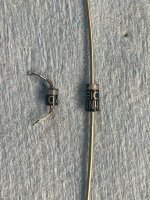
Have I made a grave error that has caused the damage to the chip or is this likely a failure of a dodgy fake chip?

The chips do not appear to match the genuine case format of lm1875 on data sheet.

I have removed some cables during test so this is not reflective of how it was when powered up as some wires not present in pic.

Attachments

  • EBDCDA40-4799-4F0D-ADCC-381460C8D1DF.jpeg
    EBDCDA40-4799-4F0D-ADCC-381460C8D1DF.jpeg
    596.6 KB · Views: 157

Just picked up an HP 333A got a few questions

As the title says, I found a nice HP 333A locally on Craigslist for $25 and although I already have a QA400 I thought why not at that price. The unit is quite clean and the guy I bought it from told me he picked it up from the lab that he worked at where they were getting rid of a bunch of old equipment. The RMS voltmeter is pretty much spot on and works great, the distortion meter however is not working all that great.

I tested it on one of my Aleph's and the QA400 was showing about .12% distortion under test where the 333A shows about .7% distortion. The unit nulled the signal manually and it seemed that the auto nulling was working fine as well when it was switched in.

I have searched the net a bit and I have the service manual. I noticed that a lot of people are replacing the dated electrolytics. A quick glance in mine shows a lot of 1975 date codes on the caps. I'm going to go through the steps outlined in section 5-40 of the manual for troubleshooting the distortion function. I was just wondering if some of you folks that are quite familiar with the HP equipment have any tips or things to check when the dist. meter is out of line?

Conflicting OB driver spec.

Its not easy being a loudspeaker designer and it likely take years to understand what to look for and in part to chose what to give up. I have been reading books and articles for a long time, but spite this, I sometimes feel stupider than when I started... LOL, and this time I want to focus on open baffle driver specifications. So lets look at what is commonly said about drivers.

One factor or indicator to look at is the EBP (Efficient Bandwidth Product) – The efficiency bandwidth product is a rough indicator measure. A common rule of thumb indicates that for when EBP >100, the driver is perhaps best used in a vented enclosure (ported, aperiodic and transmission line), while EBP<50 indicates a sealed enclosure. For EBP 50><100 either enclosure may be used effectively. Because a sealed cabinet offers cone or membrane support to a higher degree than in open air, the requirements of the suspension is different. The former can be looser so to speak. Lets check if this is correct

I am going to use two drivers from SB Audience because they perfectly encapsulate the issue at hand. Both drivers are 12". Driver #1 is the BIANCO-12OB150-01 which is marketed as an open baffle driver. Driver #2 is the BIANCO-12MW200 "non OB. According to the theory, the open baffle driver should have better suspension compliance and higher EPB values.

Driver - efficiency - Qms - Le - CMS - Rms - EPB

1) BIANCO-12OB150-01 (OB) - 96dB - 6.39 - 1.18mH - 0.25mm/N - 2.26kg/s - 64
2) BIANCO-12MW200 (non OB) - 99dB - 14.33 - 0.38mH - 0.15mm/N - 1.45kg/s - 100

Qms: A unitless measurement, characterizing the mechanical damping of the driver, that is, the losses in the suspension (surround and spider). It varies roughly between 0.5 and 10, with a typical value around 3. High Qms indicates lower mechanical losses, and low Qms indicates higher losses.
Cms: Measured in meter per newton (m/N). Describes the compliance (i.e., the inverse of stiffness) of the suspension. The more compliant a suspension system is, the lower its stiffness - The higher the force on the cone and suspension assembly the further it travels.

If we look at both Qms and Cms we can see that the are inverse to one another. As the Qms increases, Cms will decrease. An open baffle driver should therefore and theoretically have a high Qms and low Cms to be stiff enough to withstand external forces, compared to a driver mounted to a finite cabinet like mentioned before. Also, if we have a stiff suspension and high efficiency, all the better and together with a low Le, such a driver should be well suited for an open air operation or open baffle.

Q: Why then is the driver with less stiffness and less EBP (BIANCO-12OB150-01) recommended for open baffle ?

Sources:
1. https://en.wikipedia.org/wiki/Thiele/Small_parameters
2 http://www.sbaudience.com/index.php/products/woofers/bianco-12mw200/
3 http://www.sbaudience.com/index.php/products/open-baffle-drivers/bianco-12ob150/

dynamics in phono stage

I’m curious about few things and I would like to know!

I have built several stages of DIY phono, some published in DIYAUDIO, but I always have the doubt that is what gives good dynamics to a preamplifier.

I have passive phono preamps; assets; mixed some I like their sound but they do not have good dynamics and vice versa.

In all of them I use the same power source (50 watts and ultra-fast diodes); and the rest of the audio system is the same

Please what is the factor for good dynamics to be obtained?

I must be doing something really dumb?

I have an old Dac Magic DAC that takes 12V AC input from a wall wart plug. I measured the input voltage at 14V AC with the load on. I have heard many stories of improved sound with a larger/better transformer.....So I though well I have this huge oversize 16A Variac, so why not turn this down and try it before spending money on a dedicated 'better' transformer. Well I did, and when it was turned down to 14V I plugged into the DAC Magic, and it tripped the main 100A house RCD, not even the local consumer unit one I dedicate to the Hifi Circuit?!? so I tied it again, and the same thing happened.

I have taken the Neutral to the -ve and the Live to the +ve of the transformer secondary into the 2.5mm plug into the DMagic.

I figure this has something to do with the Earth and Neutral connections on the output of the Variac, but I thought the trip from an RCD was if you used the earth as a return not neutral?

Confused!?!?!

Thanks

Low noise current sink for LTP

I am working on a differential tube preamp with a CCS for the LTP. I would like to design a low noise, high impedance current source with reasonable temperature stability and would like to understand the pros and cons of using a BJT vs JFET vs MOSFET. I am looking for 10-15mA and have about 25V to work with. I don't mind some circuit complexity (although I don't have tons of space) or spending some $$ to get the best performance.

I was considering an op-amp based circuit using a precision voltage reference driving a MOSFET, but I'm not sure if this would deliver the best performance.

Thanks for any assistance.

Heat sink screws and washers - TO-220 and TO-264

Hi,

I'm screwing TO-220 and TO-264 transistors onto a heatsink. Any tips on type of screw, washer etc. to make a good thermal solution that is also durable with years of thermal cycling?

In my case, it's OK that the transistor package, heatsink (probably Cu) and screw are electrically connected.

It could be so easy that what I'm looking for is M3 screws, a drop of Loctite and a springy washer. Of these, locating the right kind of washer is probably the hardest part since it must prevent overtorquing and thermal expansion / contraction from breaking the transistor while maintaining thermal conduction.

Thanks,
Børge
Projects by fanatics, for fanatics
Get answers and advice for everyone wanting to learn the art of audio.
Join the Community
507,540
Members
7,876,075
Messages

Filter

Forum Statistics

Threads
405,677
Messages
7,876,075
Members
507,540
Latest member
Tgeb