You are using an out of date browser. It may not display this or other websites correctly.
You should upgrade or use an alternative browser.
You should upgrade or use an alternative browser.
Filters
Show only:
Elipson AS 30 Homage
- By mikers313
- Full Range
- 1 Replies
Hello! My name is Mike Ruiz Serra, I am a furniture designer based in NYC. Over the past few years I've been mastering the craft of plaster based composites for custom furnishings. I've developed an appreciation for vintage Elipson loudspeakers, as they were using similar materials and production processes.
Last year I built this set of speakers (images below) as a sort of homage to the Elipson AS 30's. I wanted to capture the aesthetic qualities and feel of the vintage Elipson's while using more modern components. For these I used Seas Prestige FA22RCZ full range drivers and designed the cabinets and ports based on the recommendations from Madisound. I use these everyday and they sound great, but I'm interested in producing more of these speakers for select clients and friends. But because I'm not formally trained in speaker design, I'm looking for some guidance.
I really love the Seas drivers, but I'm thinking about switching to Supravox speakers. Specifically the 215 Bi-Cone Signature model. I'm thinking about switching to Supravox because I heard these were the speakers that Elipson used to use, so maybe they're better optimized for this unconventional cabinet design? Sadly I'm unable to get a hold of anyone from Supravox and I was wondering if anyone has any experience with these speakers. I'm mainly trying to figure out: What is the recommended cabinet volume and port size/depth? Is dampening necessary on the inside? I'm also trying to figure out the ideal wall thickness for my material, not sure if this matters.
I'm also considering just sticking with the Seas drivers, as there seems to be more support for these.
Looking forward to hearing your thoughts on this, thanks!

Alpine 3566 issues
Hello, I have an Alpine 3566 that was purchased from a Japan site. The seller claimed the amp was working, however there was no audio output.
I completely replaced all electrolytic caps in the amp. The amp now powers up but goes into protection mode for about four minutes, then the protection led goes green and the amp provides audio. The four 2SC4024 transistors in the "cancel" circuit of the inverter get quite warm after a few minutes , I then pull power away to eliminate any further damage. I probed the uPC4094C chip . Pin 5 has a sawtooth pattern, both pins 9 and 10 have the square wave but the wave looks distorted to me. pins 13 and 14 have 5 volts. I have since taken out the rectifiers to disconnect the power supply from the output section. The protection led immediately goes green and the power section stays on. The four 2SC4024 transistors only get warm now but the square wave still concerns me. Any ideas on what to check? Thank you.


I completely replaced all electrolytic caps in the amp. The amp now powers up but goes into protection mode for about four minutes, then the protection led goes green and the amp provides audio. The four 2SC4024 transistors in the "cancel" circuit of the inverter get quite warm after a few minutes , I then pull power away to eliminate any further damage. I probed the uPC4094C chip . Pin 5 has a sawtooth pattern, both pins 9 and 10 have the square wave but the wave looks distorted to me. pins 13 and 14 have 5 volts. I have since taken out the rectifiers to disconnect the power supply from the output section. The protection led immediately goes green and the power section stays on. The four 2SC4024 transistors only get warm now but the square wave still concerns me. Any ideas on what to check? Thank you.
speaker protection
- By milosus
- Solid State
- 59 Replies
Hello everzbody, i looking for speaker protection (dc protection) but without power supply that i can mount directly on speaker , i saw couple of these devices but i cannot find schematic
Twin Sub Towers, 8.2 Ft^3 20hz Tuned Bass Reflex with Dayton MX15-22 Drivers
- By MalVeauX
- Subwoofers
- 13 Replies
Hi all,
I completed my latest project, a high value inexpensive build based on the Dayton MX15-22 drivers that were on sale a while back for a pretty deep discount from PartsExpress. Pretty decent driver for the cost when on sale. These towers are 50 inches tall by 20 inches by 20 inches. The slot port is at the top and exits behind it with a 3" x 18.75" opening and a total length of 34.6 inches. I modeled them in larger cabinets in WinISD and then built a physical model with scrap to verify my calculations for my port and my final cabinets show the 20hz tuning pretty precisely so I'm happy with how it all worked out. The front is double baffled and I used 1.5x2.5 stud for bracing. Each driver is powered by a single Behringer NX3000 that I got on deep sale (50% off) in bridged mode and they're handled by a miniDSP 2x4 HD. The cabinets are made with 3/4th inch ply that already had Birch veneer on them that I found at Lowes for an ok price and I stained them with Early American minwax and sealed with a satin poly.
50" x 20" x 20" Cabinets
Bass Reflex, 20hz Port Tuning Frequency
Net Internal Volume 8.2 cubic feet
Dayton MX15-22 Drivers (wired in series; 4ohm)
Behringer NX3000 Amplifier (Bridged; each)
MiniDSP HD 2x4

Cabinet 1 DATS V3 Impedance Sweep to verify port tuning frequency:

Cabinet 2 DATS V3 Impedance Sweep to verify port tuning frequency:

Near field measurement of the driver and the port to show the relationship and also examine the port's output which has a nice gentle peak SPL output at the 19~20hz area.

Here's the two towers referenced at 95db individually and then with time/phase alignment in the miniDSP to get a summation result in in the dark blue line. The final net summation gain is about +5db from 17hz to about 60hz. No smoothing applied.

And finally, I use the summation results to then apply a heavy house curve EQ that has an overall 15db slope down to 19hz; again no smoothing applied. The room is 18 feet x 14 feet x 8 feet. Currently I have -6db in the miniDSP on the output as I have lots of headroom still from the summation gain and was peaking 115db while watching a few heavy scenes with my AVR at -12 and -10 to get an idea of things while auditioning and running REW RTA to see the peaks. So the amp limiter lights never blink and I'm comfortable with the 110db peaks. More than that and It starts to be too loud for comfort. At max output, everything rattles and shakes, and I'm not about that kind of noise. Overall they effortlessly do their job with lots of room to spare.

Very best,
I completed my latest project, a high value inexpensive build based on the Dayton MX15-22 drivers that were on sale a while back for a pretty deep discount from PartsExpress. Pretty decent driver for the cost when on sale. These towers are 50 inches tall by 20 inches by 20 inches. The slot port is at the top and exits behind it with a 3" x 18.75" opening and a total length of 34.6 inches. I modeled them in larger cabinets in WinISD and then built a physical model with scrap to verify my calculations for my port and my final cabinets show the 20hz tuning pretty precisely so I'm happy with how it all worked out. The front is double baffled and I used 1.5x2.5 stud for bracing. Each driver is powered by a single Behringer NX3000 that I got on deep sale (50% off) in bridged mode and they're handled by a miniDSP 2x4 HD. The cabinets are made with 3/4th inch ply that already had Birch veneer on them that I found at Lowes for an ok price and I stained them with Early American minwax and sealed with a satin poly.
50" x 20" x 20" Cabinets
Bass Reflex, 20hz Port Tuning Frequency
Net Internal Volume 8.2 cubic feet
Dayton MX15-22 Drivers (wired in series; 4ohm)
Behringer NX3000 Amplifier (Bridged; each)
MiniDSP HD 2x4
Cabinet 1 DATS V3 Impedance Sweep to verify port tuning frequency:
Cabinet 2 DATS V3 Impedance Sweep to verify port tuning frequency:
Near field measurement of the driver and the port to show the relationship and also examine the port's output which has a nice gentle peak SPL output at the 19~20hz area.
Here's the two towers referenced at 95db individually and then with time/phase alignment in the miniDSP to get a summation result in in the dark blue line. The final net summation gain is about +5db from 17hz to about 60hz. No smoothing applied.
And finally, I use the summation results to then apply a heavy house curve EQ that has an overall 15db slope down to 19hz; again no smoothing applied. The room is 18 feet x 14 feet x 8 feet. Currently I have -6db in the miniDSP on the output as I have lots of headroom still from the summation gain and was peaking 115db while watching a few heavy scenes with my AVR at -12 and -10 to get an idea of things while auditioning and running REW RTA to see the peaks. So the amp limiter lights never blink and I'm comfortable with the 110db peaks. More than that and It starts to be too loud for comfort. At max output, everything rattles and shakes, and I'm not about that kind of noise. Overall they effortlessly do their job with lots of room to spare.
Very best,
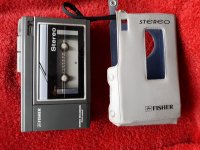
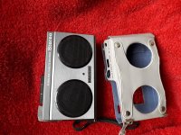
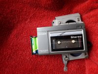
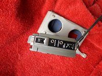
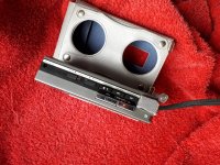
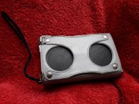
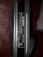
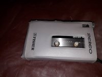
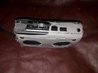
Fisher PH 55 walkman
I have no ideea how much I should ask on it, but looks pretty rare.Do you have an ideea for a good price?It has stereo mike for recording and the speed pitch control has a huge range.
Attachments
-
 20221216_133959.jpg473.8 KB · Views: 197
 -
 20221216_134010.jpg624.5 KB · Views: 141
 -
 20221216_134105.jpg587.6 KB · Views: 149
 -
 20221216_134122.jpg423.9 KB · Views: 130
 -
 20221216_134136.jpg667.7 KB · Views: 132
 -
 20221216_134030.jpg516.1 KB · Views: 125
 -
 20221216_133929.jpg580.9 KB · Views: 124
 -
 20221216_050242.jpg636.7 KB · Views: 145
 -
 20221216_050255.jpg364 KB · Views: 124
 -
 20221216_050502.jpg473.7 KB · Views: 129
 -
 20221216_050525.jpg401.1 KB · Views: 132
Should mid speakers be above ear level?
- By oon_the_kid
- Multi-Way
- 21 Replies
Hi,
By and large I think most speakers would place the mids below ear level with the tweeter at ear level. However if you think about it, most of the time the source of sound will be above you. In a jazz bar, you are sitting down and the singer is on stage and the PA speakers are on stands. In an orchestra the you are sitting below and the musicians are on top of a stage. So in most cases the sound source is above ear height. To achieve most accurate imaging. I believe speakers should be slightly above you
What are your thoughts and arguments for or against this?
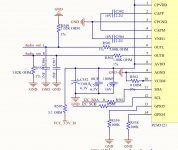
Voltage divider Input line class D tpa3110d2
Here is a schematic of jbl charge 3 i just want to ask why 1k resistor divider is used in audio output from main chip and it goes to amplifier input , and what if i use 1k alone in series instead of divider ? I m making a Bluetooth speaker and I just want to reduce disortion at full volume..please help..
Attachments
Multi-component controller
- By ASEMechanic
- Room Acoustics & Mods
- 10 Replies
Looking to build a listening room in my basement with different combinations of pre-amps, amplifiers and speakers. It be strictly a 2 channel system with variations of tube and solid state equipment as well as a variety of speakers.
Does anyone have a suggestion or recommendation on a switching controller that could handle input and output selctions, sort of like what they have in profesional listening rooms? Something where I can select different combinations? For example, select pre-amp A, run through amplifer C, and then output to speaker set B.
I'm sure I can call a few local places in ATL, but thought I'd check here first. Google isn't coming up with squat.
Thanks!
Seas Thor Crossover help
Hello,
I have inherited a pair of speakers: seas thor kit in Planet 10 quarterwave transmission line cabinets which are 49.5 x 9 x 13 inches. These belonged to two great men in my audio club and now I have inherited them. I believe they have the original crossover or something else that does not work. The speakers produce phenomenal (overpowering) deep bass and and a very forward midrange and treble that is highly detailed and fatiguing. I am looking for a crossover schematic that will suit this speaker without throwing out all the great bass and detail. I am happy to splurge on high quality components for the crossover as the drivers are excellent.
My friend that had these speakers said that this forum has had several different clever people work on this before and I am hoping that I can refine these beauties with help from the DIY community.
Regards
Rhett
Attachments
Tomcat Audio Tube Mono Blocks FS:
- Swap Meet
- 1 Replies
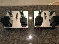
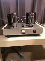
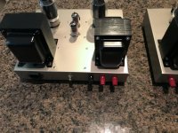
This is a pair of Tomcat Audio Mono Blocks.
They are rated at 60 watts,the power tubes are Tung Sol KT120 you can also use KT88 or EL34.
The phase splitter uses 12au7 the Driver tube can use 12at7 or 12au7
They use very nice Hammond Transformers.
Front illuminated Bias Meter with adjustable bias for each power tube.
They are less than 6 months old with little play time on them.
Great sounding mono blocks with plenty of power to spare.
Local pickup only Huntersville,NC. $1350
Attachments


Pioneer CDP non runner
- By peteramp
- Digital Source
- 2 Replies
Hello all
I purchased a Pioneer PD-S505 CD player as a non runner.
The symptoms are:
Turntable starts slowly and runs continuosly with no way of being able to stop it other than disconnecting the mains plug.
The carriage motor moves the mechanism to the outside of the disc, and if not shut off, will repeatedly bottom against the end stop.
The laser tries to focus, however there is no evidence of any beam. The lens is affixed to the laser assy (hasn't fallen out).
If put in Test Mode, the REW and FF buttons on the front panel move the carriage in the opposite directions, ie REW sees the carriage moving towards the outside of the disc.
The disc spins up without any button prompts. No other buttons are effective in Test Mode.
Voltages at test points look OK.
The tray switch and the INSD (inside switch) are both functioning.
Both carriage and spindle motors ar OK.
Any thoughts on this?
Cheers
Single tube, Single ended, 20W, impossible?
- By dannydanger
- Tubes / Valves
- 61 Replies
Ok, going way out on a limb here perhaps but, is there a valve in existence, a large transmitting tube perhaps, that is capable of producing 15-20W in a single ended design, with no driver? I imagine it being some super high voltage monster, is there a valve that could do it or is it a pipe dream?
BAT Vk-500 schematics info??
- By Zero Cool
- Solid State
- 3 Replies
anyone have any service info or schematics for a VK-500 power amp?
Speaker box with multiple drivers understanding the sum of db curves of each driver
- Multi-Way
- 7 Replies
So when calculating boxes for a speaker with multiple drivers you get a curve for each driver
One driver will produce -18db of 70hz
The second driver will produce -6db of 70hz
Just looking at curves for each driver
Does this mean the the final product, the speaker will have a curve which sums the bass output of both drivers and will look flatter than each individual curve?
Attached is an example of mark audio alpair 5 gen 3 + peerless 5.25 woofer. Alpair will have its own sealed box which will be encapsulated into a bigger box containing peerless woofer
Red curve is mark audio alpair 5 gen 3 in .5 liter box.
Blue curve is peerless sds-135F25CP02-04 in a closed 3L box.
Green curve is peerless sds-135F25CP02-04 in a vented 3L box.
If I decide to make a complete closed box system will the final speaker bass performance be the sum of red + blue curves?
How to calculate how much bass will be contributed by alpair 5 to final result. Doesn't it ad like 3db to final result. Is it just adding the DB values st a certain frequency?
Reason I decided to keep alpair 5 in closed box is so it could handle more power and not bottom out. I like to have good amount of headroom.
For Sale Salas L Adapter on Raspberry Pi footprint header powered
- By thetraveller
- Swap Meet
- 0 Replies
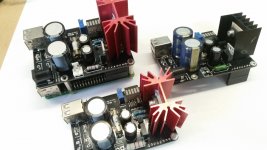
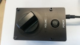
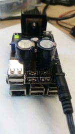
As mentioned on my earlier thread here are some more Salas L adapter circuits placed on a raspberry pi board outline for music servers that run Moode Audio. I have made some new ones with a changed component footprint positioning to better suit the other boards in my stack, So the old ones are for sale if anyone is interested. I will list them as I swap out my old ones.
The 3 shown here power the Pi through the IO header. White connectors supply 5VDC. The usb is across the output and supplies 5v. It is basically Mr Salas fine circuit with a few add ons. My Pi running Moode only drew about 500mA. If you were drawing more you might need a bigger heatsink. My heatsinks didnt get hot. It was supplied by 9v dc by an old linear wall pack. There is a provision on the board to fit diodes if you wanted to power it by a suitable AC voltage but I only fed it from 9 VDC.
$45 AUD each. I will throw in a volume pcb front panel if you want one. I have made PCB front panels for a few of my projects and the end result can look quite good. I fitted a rotary encoder on these and connected it to 3 pins of IO and used it for volume control in Moode. It worked well.
prefer Australian or NZ postage.
Attachments


WTB Philips AD 4800 M Speaker
I am looking for at least 1 of these drivers, however I am willing to buy pairs.
Here is some info: http://telefunken.te.funpic.de/philips61/philips120.jpg
Please let me know if you can help. Thanks!!
Here is some info: http://telefunken.te.funpic.de/philips61/philips120.jpg
Please let me know if you can help. Thanks!!
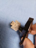
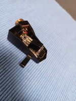
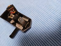
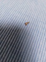
Lab Craft Type 605 Scandinavian Turntable Headshell Issue?
- By CliffR52
- Analogue Source
- 43 Replies
Hi All.
Working on a Lab Craft Type 605 Scandinavian Turntable and noticed the fine screw which holds the Cartridge to the Head is not long enough.
I suspect partial thread stripping in initial part of the cartridge plate.
The Cartridge includes the Markings "2R2 Japan"
The fine screw has under cap thread length of 5mm.
I'd say it needs 7mm-8mm.
What thread size would this be.
Are such screws common or readily available?
Attachments
Capacitors
I have an old poweramp Denon POA2400 that i want to recap and give a little Tlc. The main capacitors in the powersupply are Nippon Chemicon 10000uf 80v
seriesDL which are probably obsolete now, but when i search for it online, it feels more like they dont exist at all. Do anyone here know anything about that specific series?🙂
seriesDL which are probably obsolete now, but when i search for it online, it feels more like they dont exist at all. Do anyone here know anything about that specific series?🙂
Validation as a designer
- By easphyx
- The Lounge
- 98 Replies
How do you deal with the lack of feedback to your designs and general validation as a designer? I'm depressed to be honest...
FS: one pair of Nelson Pass A40 PCBs
FS: Nelson Pass A40 PCBs
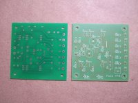
UPDATE: a new batch of PCBs arrived! See post #17 below for photos of a bare PCB, post #28 for the schematic, post #33 for photos of a sample build.
The price is $10 per pair of boards plus shipping. Estimated USPS shipping prices are $5 for the continental U.S., $12 for Canada, $16 for Europe and Australia, and probably for most of the other countries. PM me if interested.
For details on the amplifier see the relevant article on FIRSTWATT web site and another one for substituting modern parts. The PCBs are double sided and follow the original 1978 design. Each 3"x3" PCB is for one channel front end only (power stage is off board), so you'd need a pair for stereo.
Attachments
Q: P.Turner's dynamic BIAS circuit
- By LinuksGuru
- Tubes / Valves
- 4 Replies
Hi,
I run across interesting and simple solution of dynamic BIAS circuit designed by P.Turner. Looks like it have pros of both of fixed and cathode BIAS. However, I have some doubts that it works as intended. There are 2 versions of the schematic dated 2003 and 2014, I have attached both, and will refer in latest version in my text.
Web mirror of article, original site doesn't exists anymore.
https://www.vacuum-tube.eu/www.turneraudio.com.au/300w-5-bias-stabilizer.html
At first sight, it even protects tube against over-current and overheating, yet voltage on cathode resistors R12/R13 820 Ohm will decrease when transistors Q1/Q2 start to conduct, leaving protection circuit off. Transistors in dynamic BIAS are in series with resistors only 33 Ohm. Although hard clipping with low-frequency signal and consecutive output tube over-current is an unlikely scenario, circuit need to be more foolproof. I think R20/R21 which are in series with BJTs must be increased to 300 - 400 Ohm.
Please share your opinion and ideas. Thanks in advance.
Attachments
DIY corner bass traps. “Help”.
- By Ibester
- Forum Problems & Feedback
- 6 Replies
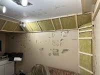
Hello all!! I currently in the process of treating my own mixing and mastering room in my house. I’m building corner bass traps. My dilemma is I see “everywhere” that everyone covers their panels and traps with cloth. But I was going to cover mine with acoustic 1-1/2” or 2-1/2” foam. It would be easier and look nicer, and I’ll get the extra thickness for more sound absorption. “So I think” but I may be blocking the audio, thus not letting the traps do their job. Please help. And thank you. Cloth or foam. Thanks again. I’ll post pics.
Attachments
Earth hum Bad Sherwood DEK-7U
- By Moondog55
- Analogue Source
- 5 Replies
I just got this cheap [ $50-] turntable for the shed and plugging it into my little party mixer I have the worst earth hum.
There is no wire connector with this TT for earth connection to the amp or pre-amp/mixer and the instructions on-line are no help.
Is there a workaround or does simply using the inbuilt preamp and treating it as a line level input work best?
I haven't yet tried using line inpiut as it means taking everything apart and it's almost time for me to start cooking dinner
field coil power supply
- By richmain
- Power Supplies
- 19 Replies
Looking for a variable power supply for a pair of Oleg Rullit lab 8 field coils.Needs 0-120 vdc.Any ideas or circuits would be great.
Yet another Loudspeaker Relay Switch
Hi,
I need to build a system able to connect and remotely switch my 2 amplifiers (Both transistor based) with the same loudspeaker set (Right, Left and Sub out). I've already read many posts about loudspeaker switching (Considering both mechanical and DIY Solid state relay), but I need some suggestions.
The Switch control unit would be arduino (ESP8266) based, and both my amplifiers can be remotely controlled (RS232 and IR), so what i was thinking to prevent any sort of problems (like arcing) is:
And talking about the relay: I was thinking about using a serie of DPDT, Latching relay consisting of:
Should this be a good idea to build a safe Loudspeaker switch? Have you got any suggestions about the relay specs to find?
Why was a Latching relay never considered? It should be better as there is no signal needed to keep the NO state closed or is there something I've not considered specifically for loudspeaker DC output?
Thanks!
I need to build a system able to connect and remotely switch my 2 amplifiers (Both transistor based) with the same loudspeaker set (Right, Left and Sub out). I've already read many posts about loudspeaker switching (Considering both mechanical and DIY Solid state relay), but I need some suggestions.
The Switch control unit would be arduino (ESP8266) based, and both my amplifiers can be remotely controlled (RS232 and IR), so what i was thinking to prevent any sort of problems (like arcing) is:
- Remotely Switch off both the amplifiers outputs
- Select the "Active" amplifier via relay
- Switch on the Active amplifier
And talking about the relay: I was thinking about using a serie of DPDT, Latching relay consisting of:
- One Power Relay used for ground connection for both the loudspeakers
- One Power Relay for each loudspeaker positive
- One Signal Relay for Subwoofer ground connection
- One Signal Relay for Subwoofer positive pole
Should this be a good idea to build a safe Loudspeaker switch? Have you got any suggestions about the relay specs to find?
Why was a Latching relay never considered? It should be better as there is no signal needed to keep the NO state closed or is there something I've not considered specifically for loudspeaker DC output?
Thanks!
External components needed for new dc-dc converter
- By neebster
- Analog Line Level
- 6 Replies
In the past, I have built my preamps using +/- 15v rails coming from a CUI PQP3-D12-D15-D dc-dc converter, fed by a suitably large 12v linear supply. I use the recommended external components for ripple reduction and EM emissions. It's sufficiently quiet, and has worked well for me.
However, I have a new project where I will be using a lot of components, some of which are power-hungry. So I need more juice.
I know it's expensive, but I was looking at a Mean Well DKE10A-15 dc-dc converter. However, the datasheet includes absolutely no reference to external components. It does say that EMC circuitry is built-in, and that it has a 60mV ripple max. But there's no equivalent circuit diagram, either.
So is this a truly "black box" solution? I just need the converter device and no other components? Or should I still bypass it with electrolytics and such? What about a ceramic cap from -v in to gnd out? Again, this may be included already but I have no way of knowing.
don-audio.com
Hi,
Does anybody know if https://www.don-audio.com/Start is still active?
I ordered a pair of Edcor PC600/15K transformers the 21 September. According to their website these should be in stock and the invoice said estimated shipping date 25 September. However, I still haven't received them and logging into my don-audio account I can see that the transformers is still pending shipment. I have tried contacting don-audio using both e-mail and the contact-form on their website without any reply.
Any of your guys bought anything from don-audio recently?
Mogens
Zaph's HiVi B3S problem! Need advice on Tangband W3-881SJF?
- By KevinI
- Full Range
- 10 Replies
So I purchased a pair of W3-871 about 10 years ago, in the hopes of building a small computer speaker. I never did because I couldn't find any small amp to drive it. Now that all these chinese Class D amps are all over I finally finished building it. It sounds ok, and I gave it away to a friend. So I was looking to build another cheap amp and speaker combo.
And I noticed that Zaph has a new HiVi B3S version that he touts as even better than the TB. http://www.zaphaudio.com/audio-speaker18.html
So I bought them, and made one. Well, they sound like crap. He warned that it would sound like crap unless you have an active crossover or a home theater receiver. But I was maybe thinking that he was just a little picky about how muddy the bottom sound. Well he's not wrong, its just bad, really bad. So if any of you think that you might be able to use it the bottom sounds like mush and resonates badly (not sure if I'm saying this correctly?) Well it's a pity because it would be a nice small bookshelf speaker for a computer. I wouldn't consider using this in a HT setup unless you have a really small room? So paring this speaker with a HT setup is odd, and I can't use it as a bookshelf speaker without an amp that can active high pass it properly. It's a loss for me.
Now I'm trying to save it. But I'm not a speaker builder in the sense I only know how to cut wood. So I leave the instructions and designing up to everyone else. I spent yesterday looking at how to design something and this is what I came up with.
The option I'm going towards right now I see is a TB W3-881SJF from PartsExpress. It's $32 dollars (much more expensive than the $12 HiVi) and I don't have any kinds of experience in designing boxes before, but plugging the numbers into WinISD, I'm looking to try and get it into a .089 cuft box with a tuning freq of 90 and a 1-1/2" PVC port with a 3.5" length.
It used to be a .12cu ft box, but I redesigned it to as low as a .089 cuft box. The design takes a minimal amount of cuts. Using 3/4" MDF, I just make one single cut a 5.5 x 7 cut.

WinISD I choose a 90hz tuning (no idea what this means but it looks good?) Graph doesn't look so bad. I downloaded the profile from LoudSpeakerDatabase http://www.loudspeakerdatabase.com/TangBand/W3-881SJF

I choose a ported design with a 1.25" PVC and about 3.6" length for what I think is acceptable port noise at 10W

There's not going to be any notch filter since I have no idea how to make them or how this setup needs them. So it's just going to be a straight plug into the terminals.
Anyone have any suggestions or see any glaring issues with my design above?
And I noticed that Zaph has a new HiVi B3S version that he touts as even better than the TB. http://www.zaphaudio.com/audio-speaker18.html
So I bought them, and made one. Well, they sound like crap. He warned that it would sound like crap unless you have an active crossover or a home theater receiver. But I was maybe thinking that he was just a little picky about how muddy the bottom sound. Well he's not wrong, its just bad, really bad. So if any of you think that you might be able to use it the bottom sounds like mush and resonates badly (not sure if I'm saying this correctly?) Well it's a pity because it would be a nice small bookshelf speaker for a computer. I wouldn't consider using this in a HT setup unless you have a really small room? So paring this speaker with a HT setup is odd, and I can't use it as a bookshelf speaker without an amp that can active high pass it properly. It's a loss for me.
Now I'm trying to save it. But I'm not a speaker builder in the sense I only know how to cut wood. So I leave the instructions and designing up to everyone else. I spent yesterday looking at how to design something and this is what I came up with.
The option I'm going towards right now I see is a TB W3-881SJF from PartsExpress. It's $32 dollars (much more expensive than the $12 HiVi) and I don't have any kinds of experience in designing boxes before, but plugging the numbers into WinISD, I'm looking to try and get it into a .089 cuft box with a tuning freq of 90 and a 1-1/2" PVC port with a 3.5" length.
It used to be a .12cu ft box, but I redesigned it to as low as a .089 cuft box. The design takes a minimal amount of cuts. Using 3/4" MDF, I just make one single cut a 5.5 x 7 cut.
WinISD I choose a 90hz tuning (no idea what this means but it looks good?) Graph doesn't look so bad. I downloaded the profile from LoudSpeakerDatabase http://www.loudspeakerdatabase.com/TangBand/W3-881SJF
I choose a ported design with a 1.25" PVC and about 3.6" length for what I think is acceptable port noise at 10W
There's not going to be any notch filter since I have no idea how to make them or how this setup needs them. So it's just going to be a straight plug into the terminals.
Anyone have any suggestions or see any glaring issues with my design above?
Defective Power Entry Module in Back Panel Kit
- By dmcgown
- The diyAudio Store
- 4 Replies
I was trying to slip on a 0.2 in Faston connector to one of the switch terminals (L), and the blade on the switch was driven into the body of the switch, I managed to pull it back into position, but could not slip on the connector. It was the correct size connector...I used the same on the (N) terminal.
Is there an higher quality version of this module. Maybe Schurter is cutting corners but it seems cheap compared with a similar module I bought a few years ago from Mouser.
David
Is there an higher quality version of this module. Maybe Schurter is cutting corners but it seems cheap compared with a similar module I bought a few years ago from Mouser.
David
Push pull output transformer, no phase splitter?
- By brightcity
- Tubes / Valves
- 23 Replies
Hello, I am using a push pull output transformer without phase splitting the two sides in the following schematic.
Would this work? And what will it sound differently from an addition of a transformer interstage?
Would this work? And what will it sound differently from an addition of a transformer interstage?
Attachments
need help choosing an amplifier
there is a focal ps 165 v1. Which amplifier to choose for it.?
Which is better to choose audison sr 4.500 (130 rms in 1 ch) or audison sr 4.300(85 rms in 1 ch)
Or tell me some other amplifier.
It's hard to choose))
Which is better to choose audison sr 4.500 (130 rms in 1 ch) or audison sr 4.300(85 rms in 1 ch)
Or tell me some other amplifier.
It's hard to choose))
DSP filter electronics: options
I am evaluating DSP options for a 4-way active speaker. The MiniDSP 4x10HD is an obvious choice, the performance is good, and the price is nice.
What other options are out there? I need 2 input channels (analog) and 8 output channels (analog). Either balanced XLR or unbalanced RCA is fine. Spdif / toslink digital inputs are a nice plus, but not necessary.
Thanks !
What other options are out there? I need 2 input channels (analog) and 8 output channels (analog). Either balanced XLR or unbalanced RCA is fine. Spdif / toslink digital inputs are a nice plus, but not necessary.
Thanks !
Upgraded Eminence Alpha15a 15" woofers
- By zs1962
- Full Range
- 7 Replies
Eminence upgrades their legendary Alpha15a and they do it with PureAudioProject.
PureAudioProject launches two 15″ open baffle woofers that are direct upgrades of Eminence legendary Alpha15a.
OB-EA15se - 15” Ferrite Woofer for Open Baffle with 2″ Voice Coil motor and Shorting Ring
OB-EA15neo - 15” Neodymium Woofer for Open Baffle with 2.5″ Voice Coil motor and Shorting Ring


Both are designed and manufactured by Eminence for Open Baffle and exclusively for PureAudioProject

PureAudioProject Trio15TB with OB-EA15neo 15" Drivers
In most cases, both can replace the Alpha15a without the need to change the crossovers.
The new drivers are based around the performance characteristics of the Eminence Alpha15a and are designed to bring further refinement and musicality to our TRIO15 product line, as well as to any Open Baffle speakers !
Here is what Jerry McNutt, Eminence Product Design Manager says about the two drivers:
“These are the higher performance and lower distortion 15” drivers that have been specifically optimized for Open Baffle use. They have the same cone and surround as the Alpha15, but we went with stronger magnets and 2.5” VC motor to gain more motor strength, increase linearity, increase power handling, lower power compression, and to be able to add a shorting ring to lower distortion and lower the Le. To further lower distortion and cut down on basket ringing, with the ferrite model we increased the thickness of the highly ribbed and windowed basket form 18ga to a much heavier 16ga steel and with the Neo model we use our rigid cast Aluminum frame, a very open basket for minimum turbulence and Ridgid cast Al frame and push-button terminals. These new 15"s have 5.55mm and 6.03mm of Xmax to move more air down deep...”
Not only do they play low, their refinement and improved linearity allows them to extend into the mid-range with most natural sounding mid, up to 1.2KHZ and even more, allowing smooth integration with horn and hi-frequency drivers such as the BeymaTP150, Heil AMT and more; and it is for the first time and with our modular Open Baffle concept, audio enthusiasts that are not DIYers can tailor their sonic taste around their drivers of choice, simply by changing the baffles with the mid/hi frequency drivers and their crossover.
Q: How do these drivers sound ?
These drivers have similar sonic feel as the Alpha15a but they are more powerful and faster, more focused and clear, a bit dryer, deeper and punchier... and they play great mid 🙂 in simple words, they are very musical, transparent and realistic !
Q: Can these drivers replace Alpha15a in current configurations ?
Yes they can ! In our Trio15TB the same crossovers work with all three drivers, Alpha15a, OB-A15SE and OB-A15SEN...
Q: How do the two models differ with regards to amplification ?
The OB-EA15SE (Special Edition Ferrite) is a straight forward replacement to the Alpha15a and matches any amplification, incl. low power SE tube amps. The OB-EA15SEN (Special Edition Neodymium) is a perfect match with higher power amps.
Technical Specifications
SPL Alph15a vs EA15se vs EA15neo
Mechanical Drawings OB-EA15se
Mechanical Drawings OB-EA15neo
for more information contact us to info@pureaudioproject.com
PureAudioProject launches two 15″ open baffle woofers that are direct upgrades of Eminence legendary Alpha15a.
OB-EA15se - 15” Ferrite Woofer for Open Baffle with 2″ Voice Coil motor and Shorting Ring
OB-EA15neo - 15” Neodymium Woofer for Open Baffle with 2.5″ Voice Coil motor and Shorting Ring
Both are designed and manufactured by Eminence for Open Baffle and exclusively for PureAudioProject
PureAudioProject Trio15TB with OB-EA15neo 15" Drivers
In most cases, both can replace the Alpha15a without the need to change the crossovers.
The new drivers are based around the performance characteristics of the Eminence Alpha15a and are designed to bring further refinement and musicality to our TRIO15 product line, as well as to any Open Baffle speakers !
Here is what Jerry McNutt, Eminence Product Design Manager says about the two drivers:
“These are the higher performance and lower distortion 15” drivers that have been specifically optimized for Open Baffle use. They have the same cone and surround as the Alpha15, but we went with stronger magnets and 2.5” VC motor to gain more motor strength, increase linearity, increase power handling, lower power compression, and to be able to add a shorting ring to lower distortion and lower the Le. To further lower distortion and cut down on basket ringing, with the ferrite model we increased the thickness of the highly ribbed and windowed basket form 18ga to a much heavier 16ga steel and with the Neo model we use our rigid cast Aluminum frame, a very open basket for minimum turbulence and Ridgid cast Al frame and push-button terminals. These new 15"s have 5.55mm and 6.03mm of Xmax to move more air down deep...”
Not only do they play low, their refinement and improved linearity allows them to extend into the mid-range with most natural sounding mid, up to 1.2KHZ and even more, allowing smooth integration with horn and hi-frequency drivers such as the BeymaTP150, Heil AMT and more; and it is for the first time and with our modular Open Baffle concept, audio enthusiasts that are not DIYers can tailor their sonic taste around their drivers of choice, simply by changing the baffles with the mid/hi frequency drivers and their crossover.
Q: How do these drivers sound ?
These drivers have similar sonic feel as the Alpha15a but they are more powerful and faster, more focused and clear, a bit dryer, deeper and punchier... and they play great mid 🙂 in simple words, they are very musical, transparent and realistic !
Q: Can these drivers replace Alpha15a in current configurations ?
Yes they can ! In our Trio15TB the same crossovers work with all three drivers, Alpha15a, OB-A15SE and OB-A15SEN...
Q: How do the two models differ with regards to amplification ?
The OB-EA15SE (Special Edition Ferrite) is a straight forward replacement to the Alpha15a and matches any amplification, incl. low power SE tube amps. The OB-EA15SEN (Special Edition Neodymium) is a perfect match with higher power amps.
Technical Specifications
SPL Alph15a vs EA15se vs EA15neo
Mechanical Drawings OB-EA15se
Mechanical Drawings OB-EA15neo
for more information contact us to info@pureaudioproject.com
Moset relay volume control?
- By SonocusEric
- Analog Line Level
- 4 Replies
With relay controlled volume array being employed in next gen products two of which are now the best measuring integrate in the market (topping 90 and benchmark headphone amp), i had an idea that the next step would be ditching the high quality relays and using smd mosfets for the job. Yay or nay?
Ways of hiding subwoofer in a table : ideas needed.
- By Sebr023
- Subwoofers
- 51 Replies
Dont want to make a double post,
But I was suggested to ask other people for opinion of possibly doing a slot loaded subwoofer or other type of build or in order to “hide” driver from sight.
I want to build a living room subwoofer for tv and movie watching mostly, and some music. But nothing audiophile quality. I have a denon 1600h and the subwoofer will be driven by a behringer nu6000dsp.
Living room is roughly 10x10, opens on the kitchen and hallway which is 20x20.
the plan is to make and hide it as table. I was thinking of making a down firing subwoofer, but in my other thread, people said that dual opposed would be best to cancel out vibration and resonance, that over it would be best, and more out put.
So for now, I’d go for 2 Dayton UM15 in a 2.5ft^3 each.
I have ~ 40in x 20 x 20 roughly avalaible. I can give or take couple inches to accommodate.
I’d like to see what idea people can come up with in order to « hide » the 2 woofer and
I’m an okay wood worker, but I’m very new to the hobby of DIY loudspeaker, so not very good with design software and all the technical terms.
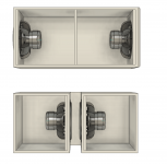
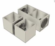
I included a screenshot of the table with 2 15’s in their 2.5ft^3 at each end of the table, and a ‘concept’ of a “slot loaded” type of subwoofer.
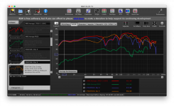
Also, I included a REW screen shot reading of actual subwoofer placement: red and green line. And driver placement at each end of the table : orange and blu-ish line.
But I was suggested to ask other people for opinion of possibly doing a slot loaded subwoofer or other type of build or in order to “hide” driver from sight.
I want to build a living room subwoofer for tv and movie watching mostly, and some music. But nothing audiophile quality. I have a denon 1600h and the subwoofer will be driven by a behringer nu6000dsp.
Living room is roughly 10x10, opens on the kitchen and hallway which is 20x20.
the plan is to make and hide it as table. I was thinking of making a down firing subwoofer, but in my other thread, people said that dual opposed would be best to cancel out vibration and resonance, that over it would be best, and more out put.
So for now, I’d go for 2 Dayton UM15 in a 2.5ft^3 each.
I have ~ 40in x 20 x 20 roughly avalaible. I can give or take couple inches to accommodate.
I’d like to see what idea people can come up with in order to « hide » the 2 woofer and
I’m an okay wood worker, but I’m very new to the hobby of DIY loudspeaker, so not very good with design software and all the technical terms.
I included a screenshot of the table with 2 15’s in their 2.5ft^3 at each end of the table, and a ‘concept’ of a “slot loaded” type of subwoofer.
Also, I included a REW screen shot reading of actual subwoofer placement: red and green line. And driver placement at each end of the table : orange and blu-ish line.
Attachments
WTB (or selling) Single Seas Excel W15CH001
So, it looks like I got scammed on ebay so if anyone has a single Seas Excel W15CH001 driver they'd be willing to let go of I'd be very interested. Ideally new and located within the EU, but more-or-less everything cosidered at this point 🙂
Alternatively, willing to let the driver I have go at a good price. It is new-in-box and with a 2020 date code.
Alternatively, willing to let the driver I have go at a good price. It is new-in-box and with a 2020 date code.
DIY XLR A/B switch pedal
- By fabrihg
- Construction Tips
- 1 Replies
Hi guys! Im having a lot of problems trying to make an a/b switch pedal! I'm trying to replicate this one
https://www.stompbeat.com/index.php?route=product/product&path=61&product_id=64
but I don't find the right diagram for the switch connection! can someone help me?
https://www.stompbeat.com/index.php?route=product/product&path=61&product_id=64
but I don't find the right diagram for the switch connection! can someone help me?
Adding a PHASE PLUG to a FR Speaker
- By Rbertalotto
- Full Range
- 10 Replies
Here is a DIY article on removing the dust cap from a speaker and replacing it with a Phase Plug....I think some might find it educational....
http://rvbprecision.com/stereo/full-range-speaker-phase-plug-addition.html
http://rvbprecision.com/stereo/full-range-speaker-phase-plug-addition.html
Miro AD1862 DAC for sale
SOLD
This my extra set of Miro AD1862 DAC board, fully populated and functional.
You need to have a set of psu to supply +/-12V and +/-5V to the DAC board and also an i2s source of your choice for it to play.
Resistors on the board are high quality, low noise ones from TAMA electric, Nikkohm. The IV resistor is DALE Blue version, which is of military grade offering high precision, tolerance and non-magnetic.
Bypass caps for the logic ICs are Kemet SMD MLCC x7r types.
Bypass caps for the digital and analog stages are Kemet MKP.
Electrolytics bypass are Nichicon FW series and Panasonic FC series for the DAC chips and for the IV op amp section are Nichicon KZ.
Op amp for IV stage in this sale is the dual op amp LME49860, mounted on the dual to single adaptor.
Fact:
1. The AD1862 chips are bought used for my testing. I have been running it for at least 2 weeks or more without a glitch. They work as they should and sound no less than the new ones from my purchase from the Rochester group buy.
2. The positive 12V input pin pad under the board has been partially lifted. However, it will have no problem soldering your pins or cable on the remaining part of the pad, and the pad on the top layer also provide full connection.
For 125USD, coffee for Miro, who has been very helpful and generous, as well as shipping with tracking included.
Lomo KINAP 1A22 compression Drivers. Anyone tried them?
- By fatbattery
- Multi-Way
- 6 Replies
Some have metal diaphragms most have nonmetallic possibly plastic and the early ones seem to have paper. These are the ones that interest me. Searching but not one forum post about sound quality. In English anyway. Can anyone help? I am tempted to buy a pair. I looking for a warm tone. Someone said there good for 600 to 12k someone said 1k to 12k. Lots showing up on the Russian Ukrainian ebay markets cheap.
Conrad Johnson USA
- Solid State
- 1 Replies
I have been emailing thesew guys ,try also to call them used also web contact form but no answer at all
Office is supposed to be at Fairfax VG
any one has an idea ?
Office is supposed to be at Fairfax VG
any one has an idea ?
Convert Jolida CD-100 to DAC?
- By JonnyGee
- Digital Source
- 0 Replies
Hello everyone,
I'm very happy with the sound of my Jolida CD-100 player. What I am not happy with is the sliding drawer mechanism which gets stuck at random times. Being old and short tempered I would like to get rid of that annoying sliding drawer (another pointless complication) by turning the Jolida into a DAC and using a Rega Apollo as the transport.
Can anyone recommend a shop that would be willing to do this conversion? Thanks, much appreciated.
Jonny
The significance of high Qms..?
I started another thread regarding midranges, and from some of the answers I got and quite a bit of frantic reading up and investigation, I made some observations which might be interesting to bounce of the forum...
it really started with an interview with Joachim Gerhard of Audio Physics, posted on Troels Gravesens web-page: http://www.speakerbuilding.com/content/1039/
Here Mr Gerhard comments that many new drivers are very heavily damped in order to give flat frequency response, something which is characterized by low Qms. He then goes on to say that many of the older drivers with much less mechanical damping and high Qms were much more dynamic.
In my previous midrange thread, a surprising many people recommended using pro-drivers for good dynamics and response.
Looking at the data for many of these drivers, I found that most of them had very high Qms, typically 4-8, whilst msot Hi-fi drivers seem to be in the 1-1,5 range.
What I also found was that most of the pro-drivers seemed to have rather ragged frequency response, perhaps a result of poor damping?
It is within this context I find two drivers very interesting as candidates for 200-3000Hz midranges for my active speaker project;
The Vifa WN 17 255 suggested to me by Calvin and the Focal 6W 4311B, which I found on the Zalytron web page.
Looking at the efficiency, suspension compliance and the Qms of these drivers, they seem to have relatively low mechanical damping, yet the frequency plot is very flat, at least compared to a lot of the aforementioned pro-drivers.
The Focal driver has a Qms of over 8, a number many times higher than for any other hi-fi unit I have seen. The frequency response is perhaps not as smooth as that of the Vifa unit, but still looks OK.
So, what I'm thinking is that these drivers represents examples of drivers which are actually reasonably linear without relying to heavily on mechanical damping, which to the best of my understanding is conductive to good dynamics and transient response.. (?)
Or am I making totally stupid conclusions here??
😀
Of course, drivers with low mechanical damping will still need to be controlled somehow if they are not to resonate and flap about uncontrolled so to speak, but an amplifier with good damping factor should contribute towards this i suppose?
Anyway, some viewpoints,and by all means corrections, on this topic would be very interesting! 🙂
Adding sub to 300b
- By Jcris
- Subwoofers
- 8 Replies
Hey
I would like to add a subwoofer to my system. I have 300b monoblocks and a 6sn7 based preamp with full range speakers (MarkAudio 12p). The preamp does have a sub output. Just looking to supplement the lower end a touch. Thinking perhaps a powered sub but not sure. Suggestions are welcome.
Thanks
I would like to add a subwoofer to my system. I have 300b monoblocks and a 6sn7 based preamp with full range speakers (MarkAudio 12p). The preamp does have a sub output. Just looking to supplement the lower end a touch. Thinking perhaps a powered sub but not sure. Suggestions are welcome.
Thanks
Musical Fidelity A100 Fans Problem
- By DrSamantha
- Solid State
- 7 Replies
I have inherited from my dad this wonderful amp (it used to be mine till I have it ti him) and my idiot incompetent brother had taken it to bits. I have rebuilt it (surprised myself there) so it works for a short time then cuts out due to that cut out switch, sounded great. My problem is the fans were just in the box loose and I do not know where to connect them. I have seen the nice line diagram put on here and I worked out where one of the fans connects but I cannot work out where the other wire goes. I tried to put a picture on here but I could not work out how. Can anyone help me please.
Forte Mod 1 / 1A
Hello
is there a big difference between Forte Modell1 and Model1A ?
Or they are similar ? A schematic would be very helpful.
On web I couldn´t any detailed informations
thx
Wolfgang
is there a big difference between Forte Modell1 and Model1A ?
Or they are similar ? A schematic would be very helpful.
On web I couldn´t any detailed informations
thx
Wolfgang
Beyma 12br70. Suitable for Sealed enclosure?
- By youknowyou
- Multi-Way
- 12 Replies
I have a Beyma 12br70 and wanted to know if it would be suitable in a 130L sealed ecnlosure.
LOW & MID FREQUENCY 12BR70 | Beyma
thanks!
LOW & MID FREQUENCY 12BR70 | Beyma
thanks!
Help to find XH-A901 NE5532P stereo tone preamp board schematic circuit
- By Mat Ure1
- Analog Line Level
- 8 Replies
Good day to all. I am a mature guy and have been in the electronics trade all my working life, I retired a number of years ago anywho I bought an XH-P901 pre amp board a couple of years ago and It has worked well up till recently it has now developed a fault. The sound is low and there is a lot of hum. I have changed the pair of NE5532P op amps and the electrolytic capacitors.
I would like to find a schematic circuit so I can investigate further.
I realise a lot of folks turn their noses up at this gear and I could buy a new board or in fact a better board for very little money but I like to tinker, it fills my time in 😴.
Thanks
I would like to find a schematic circuit so I can investigate further.
I realise a lot of folks turn their noses up at this gear and I could buy a new board or in fact a better board for very little money but I like to tinker, it fills my time in 😴.
Thanks
Mannsize. 3.5way active cardioid´ish
Mannsize. 3.5way active cardioid´ish project
Gear from old steel is real thread has time to go for 2020.
New idea is to use jbl 3730 mid/high waveguides and 4x12" on front and one 12" on the rear of the box, 4channels active.
height is gonna be 160-180cm
Gear from old steel is real thread has time to go for 2020.
New idea is to use jbl 3730 mid/high waveguides and 4x12" on front and one 12" on the rear of the box, 4channels active.
height is gonna be 160-180cm
Ground Zero GZNA 1.2500D
Hello, I would like to know if I can put irfb4115
instead of irfb31n20 thank
instead of irfb31n20 thank
Has anyone built a mini Pipe Oh?
- By tonyEE
- Subwoofers
- 12 Replies
Has anyone built the mini Pipe Oh hinted by the design notes of the Pipe Oh?
You know the six footer with a single 8 inch driver?
What kind of equalization would I need? Would a pair of Aleph 5 be enough to drive them? Or maybe a Conrad Johnson MF2100?
https://www.firstwatt.com/pdf/art_elpipeo.pdf
I want something that will add just a little bit of bass oomph to a Maggie 1.7 / A2 combo.
ADCOM Power Supplies and input circuit boards
- By Phloodpants
- Vendor's Bazaar
- 8 Replies
Hi Everyone,
I'm terrible at marketing; I'd rather be working at the bench, so I don't think many people even know I exist!
I sell fun DIY power supply and input board kits for ADCOM amplifiers.
My first product was a replacement GFA-565 circuit board, to fix the famous capacitor leakage issue with that model, and it's still my most popular item.
My shop is here.
Hoppe's Brain - Shop for ADCOM upgrade circuit boards
(Pronounced "Hoppy")
Thanks for looking!
Products:
ADCOM GFA-565 Upgraded input board (Bare board or fully assembled and tested.)

ADCOM GFA-555 Upgraded input board (Bare board or unassembled kit.)

NOTE: GFA-555 MK2 Boards are coming soon!
ADCOM GFA-535 MK1 Power Supply Upgrade Kit

ADCOM GFA-535 MK2 Power Supply Upgrade Kit

ADCOM GFA-555 Soft-Start Power Supply Upgrade Kit

ADCOM GFA-585 Replacement Circuit Boards (PAIR)

ADCOM GFA-545 Upgraded Power Supply Kit

Universal Amplifier Soft-Start Power Supply Board

I'm terrible at marketing; I'd rather be working at the bench, so I don't think many people even know I exist!
I sell fun DIY power supply and input board kits for ADCOM amplifiers.
My first product was a replacement GFA-565 circuit board, to fix the famous capacitor leakage issue with that model, and it's still my most popular item.
My shop is here.
Hoppe's Brain - Shop for ADCOM upgrade circuit boards
(Pronounced "Hoppy")
Thanks for looking!
Products:
ADCOM GFA-565 Upgraded input board (Bare board or fully assembled and tested.)
ADCOM GFA-555 Upgraded input board (Bare board or unassembled kit.)
NOTE: GFA-555 MK2 Boards are coming soon!
ADCOM GFA-535 MK1 Power Supply Upgrade Kit
ADCOM GFA-535 MK2 Power Supply Upgrade Kit
ADCOM GFA-555 Soft-Start Power Supply Upgrade Kit
ADCOM GFA-585 Replacement Circuit Boards (PAIR)
ADCOM GFA-545 Upgraded Power Supply Kit
Universal Amplifier Soft-Start Power Supply Board
Heatsinking and the Toshiba TTC004B
- By jbau
- Solid State
- 58 Replies
I want to replace the TIP41C outputs in a Class A headphone amp with TTC004B. They will be biased at about 120mA and require heatsinking, just as the 41C's do. I have two concerns/questions.
1. The TTC004B is epoxy-encased. The data sheet warns not to rely on that for insulation, but says nothing about its impact on heat transfer. Is this something to worry about?
2. The pinout of the TTC004B is ECB, the reverse of the 41C. Given #1, will turning it around and attaching the face to the heatsink provide adequate heat transfer?
Here's the link to the data sheet.
stereo pair of mics
- By hifijohn
- Everything Else
- 0 Replies
Probably the most microphone-like mic I ever made.The elements are actual mic elements, the enclosure is a peg for BMX bikes, they are perfect, just the right diameter for the mic element and other side has a 1/4" hole perfect for a 1/4" output jack.These are old designs and came in an ugly green color they look better in gold, sold is very good.
Login to view embedded media
Login to view embedded media
Fifopi vs fifolite comparisons?
- By tubo
- Digital Line Level
- 0 Replies
Hello everyone,
Does anyone have both ian’s fifopi and Andrea’s fifolite? Please let us hear your thoughts with both.
Regards to all.
Happy Holidays
Does anyone have both ian’s fifopi and Andrea’s fifolite? Please let us hear your thoughts with both.
Regards to all.
Happy Holidays
This is sick...
- By dreamth
- The Lounge
- 40 Replies
Help with small club speaker placement...
- By paulys55
- PA Systems
- 20 Replies
Looking for speaker placement suggestions. I normally do home audio/video installs but also do some commercial. Mostly offices and bars. But this client has a bar that has a side room where he would like a dj/dance sound system set up. Unfortunately I can't build the speakers because he requested warranties. So I will probably get some JBL SRX series or something similar. The room is 14ft (4.27m) wide by 60ft (18.29m) long with 12ft (3.66m) ceiling. The client isn't looking for night club levels but more like small dj gigs. Any suggestions welcome.
Technics No. SU-A80 PN:SGT37240
- Analog Line Level
- 10 Replies
Good evening folks, long time lurker here but never had much reason to post until now.
I finally got enough funds to start getting into vintage audio. I happened to pick up the following units:
Now I haven't powered these units up. Knowing that any unknown unit should not be powered until at minimum performing a visual inspection of the circuitry.
I started with the SU-A80 as it seemed it be the easiest of the two to inspected. I figured there isn't much you could damage on a (pre-amp)? Well I was dead wrong with that ***-umption. During my visual inspection of the circuit board I found two transistors that experienced a major thermal event. Both of the transistors are on the power supply section.
See images below:

Now Ive scoured the internet for any and I mean any information on this unit. Outside of parts here and there I can not find a user manual nor repair manual for this unit. I believe this is one of those pieces that could only be acquired if you were in the armed forces at the time. I say that due to the fact that its power supply can be set to 110v, 120v, 220v, and 240v.
Here is my question:
I used NTE Quick Cross to try and find replacement transistors and was recommend the following replacements.
Have a wonderful day and thank you.
I finally got enough funds to start getting into vintage audio. I happened to pick up the following units:
- Technics SU-A80 control amplifier
- Technics SU-A70 power amplifier
I started with the SU-A80 as it seemed it be the easiest of the two to inspected. I figured there isn't much you could damage on a (pre-amp)? Well I was dead wrong with that ***-umption. During my visual inspection of the circuit board I found two transistors that experienced a major thermal event. Both of the transistors are on the power supply section.
See images below:
Now Ive scoured the internet for any and I mean any information on this unit. Outside of parts here and there I can not find a user manual nor repair manual for this unit. I believe this is one of those pieces that could only be acquired if you were in the armed forces at the time. I say that due to the fact that its power supply can be set to 110v, 120v, 220v, and 240v.
Here is my question:
I used NTE Quick Cross to try and find replacement transistors and was recommend the following replacements.
- Original - 2D9 AN78M18. Recommend replacement - NTE958
- Original - 5N5 AN79M18. Recommend replacement - NTE959
Have a wonderful day and thank you.
Marantz PM7200 help finde volume potentiometer replacement
- By Lynyrd
- Solid State
- 11 Replies
Hello.
Need find equivalent of potentiometer volume for integrated amplifier MARANTZ PM7200.
Original potentiometer is dead .
It is 50k pot with 12 legs.
Need find equivalent of potentiometer volume for integrated amplifier MARANTZ PM7200.
Original potentiometer is dead .
It is 50k pot with 12 legs.
Subwoofer Filters & X-Overs: Recommended type and slope?
- By Cableaddict
- Subwoofers
- 3 Replies
I've always tuned my PA systems by ear, with decent results, but have recently decided to get more serious about it.
I bought True Audio's "TrueRTA" software (the 24 band per octave version) and am using very high-end studio omni mic and audio hardware.
So all good, but I'm having a hard time getting smooth results. Granted, I'm currently setup in a large room (using low volume to minimize nodes, etc) but am only going for a rough tweaking. Afterwards I'll do the fine-tuning outdoors.
---------------------------------------------
But I digress.
I'm setting up both 18" sealed subs,, and dual 12" ported subs, paired with EAW KF394 tops which have their HPF factory set to about 65 Hz. (That seems low to me, but that's what it is.) I'm not sure what filter TYPE they use, as it's part of the EAW "Greybox" setting. - I could probably find out, if it matters.
My question is as in the title.
I use an EAW UX3600 processor, so I have a lot of control options.
So specifically:
----------------------------------------------
HPF: Some experts have recommended 24 dB BW at maybe 5-6 Hz below the Fb, but another (A very good tech from one of the driver manufacturers) recommended a 12 dB but a little higher frequency, (closer to the box tuning) and he did not mentioned filter type.
It seems to me the 24 dB would offer more protection, though 12 dB might make sense with the 2X12" box, since the LF extension is somewhat compromised. (Fb is 43 Hz)
LPF: I've read lots of threads on lots of forums, but there's isn't a clear consensus. Folks seem equally divided between BW and L-R, though Ivan Beaver (Danley) seems to be fond of Bessel. BW seems to be the flattest, so I'm surprised it's not the clear winner.
- And slope recommendations are all over the place. Many even recommend over or underlapping at the transition point. I know it ultimately comes down to using my ears, but ughhh ......
LF Compensation: This is the one that puzzles me the most. Is it common to use a shelf filter, so as to get a very smooth result? It seems to me that this would then sort of "fight" the subs' HPF, and maybe cause phase issues? But a bell-type is really hard to dial-in.
If I use a bell-type then should I experiment with a tight Q close to 40 Hz, or a wide Q set a little higher?
-----------------------------
One last question: Is it typically recommended to go for a "roughly flat" response in the 40 Hz area, or do some guys prefer a small bump? (Same question for 80 Hz.)
If it matters, I use these rigs for both a rock band and DJ playback.
Thx.
Which drivers / Kit are these?
Hello Guys, i found a listing of a speaker nearby me. The seller states he got these from a friend who was a "hi-fi enthusiast" who unfortunately passed away.
So he doesnt know much about the speakers. Maybe you guys can help me out. Please see the photo attached. Which drivers are these? Seller only said he knows the Tweeters are from Monacor. May this be a known kit?
Thanks for your help
Login to view embedded media
So he doesnt know much about the speakers. Maybe you guys can help me out. Please see the photo attached. Which drivers are these? Seller only said he knows the Tweeters are from Monacor. May this be a known kit?
Thanks for your help
Login to view embedded media
Rotel RHB 10 caps upgrade
- By Staykov
- Solid State
- 1 Replies
Rotel RHB 10 caps upgrade
The Big one
original caps :Nichicon 22000 µF,80V, 85°C.
new one: RIFA 47000 µF, 100 V, PEH200 Series, 19000 hours @ 85°C ,ESR: 0.007ohm
original caps :Nichicon 6800 µF,80V, 85°C.
new one:RIFA 10000 µF, 100 V, PEH200 Series, 12000 hours @ 85°C
original board caps :Rubycon 1000uF/100V ,
new one Mundorf capacitor Elko 1000uF/100V 105 ° C MLytic ® AG audiograde
the small Rubycon Black Gate caps will stay on the board.
New internal wiring :van den hul d-352 hybrid.
Attachments
-
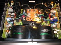 RHB-10a stock.jpg121.7 KB · Views: 556
 -
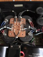 ROTEL RHB-10b.jpg149.2 KB · Views: 491
 -
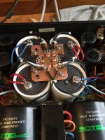 ROTEL RHB-10c.jpg204.2 KB · Views: 429
 -
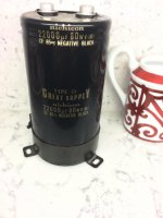 Nichicon.jpg85.9 KB · Views: 409
 -
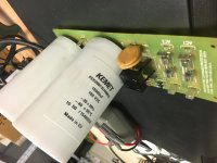 small Rifa bolt on.jpg78.9 KB · Views: 399
 -
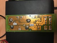 image.jpg95.5 KB · Views: 379
 -
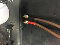 internall wire.jpg57 KB · Views: 343
 -
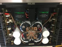 final stage.jpg107.8 KB · Views: 448
 -
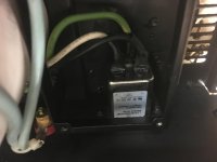 input socket.jpg54.9 KB · Views: 371
 -
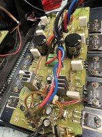 mundorf.jpg205.4 KB · Views: 127
 -
0-02-05-95ef792e64040ee6822eedc8d71507cf8ad3a623f4780748a0f1a83665fe05ad_1c6db55ad2088d.mp42 MB
Simple port question
I think this question is likely much simpler than most others relating to ports...
I'm building a pair of CSS Criton 2TD-X Towers from scratch. The design includes two 2-inch diameter, 7-1/2" long tubular ports located side-by-side in the back panel of each speaker, with the bottom edge of the ports just about an inch from the bottom. They're below the binding post cup (which I won't be using as I'm going with GR Research tube connectors).
The towers are only 8.5" wide (7" inside), and I'd like to stack the two ports vertically instead of placing them side-by-side; I'd also replace the stock straight tubes with the flared 2" Precision Port units. I'd keep the port length the same, seeing no reason to change it.
Anyone see any problem with this?
Thanks!
Component id on power supply
- By Julianhull51
- Power Supplies
- 21 Replies
Evening guys, I’m trying to restore a power supply on a Technics cassette deck and need help identifying the component shown with a blue arrow on the drawing. I assume it’s a resistor by the drawing but it’s in a transistor type casing marked: N 10 W
Any help greatly appreciated

Any help greatly appreciated
sound quality of Dayton RS100-4, Markaudio Alpair 5.3, Markaudio A7ms
- Multi-Way
- 3 Replies
just wanted to hear some opinions on these drivers
mark audio alpair 7ms 5" full range driver
https://www.madisoundspeakerstore.c.../markaudio-alpair-7ms-gold-cone-5-full-range/
mark audio alpair 5 gen 3 3" full range driver
https://www.madisoundspeakerstore.com/approx-3-fullrange/markaudio-alpair-5-gen.3-gold-3-full-range/
dayton audio rs100-4 4"(but people in revews said its 3.5")
https://www.parts-express.com/Dayto...MI1PWEzrr4-wIVC4TICh2wXAdYEAQYASABEgLNX_D_BwE
i dont blast music loud. but would be good to have some headroom for occasional blasts.
enclosures i am trying to keep under 3L
i am a little worried about power handling of mark audio. 3" driver is rated for 5 good watts i assume,
alpair 7ms is rated at 15watts
dayton rs100-4 50watts.
dayton reviews i've seen are mostly by gamers talking in college dorm on how loud these speakers can blast
some people complained that tremble tonality is a little off and they would use a tweeter with rs100-4
could not find anything bad about mark audio drivers.
can anyone comment on sound quality of these.
i am leaning towards mark audio alpair 5.3. dave (planet10) recommended them in another thread and they seem like best thing in under 3 liter volume. my only concern is power handling.
whats the smallest volume that can be used with alpair 7ms
Copying electronic XO to passive - how hard is it?
- Multi-Way
- 3 Replies
My project that I want to start is almost all ready as far as research goes, everything up to this topic has been calculated and figured for but there is this one hurdle….
If and when I design and run my xo network for my complicated unity horn, I need to know, what if any route I can take if I cannot get through learning XOs.
I plan on designing and making a 60X90 2-way unity horn and bench testing it with a dsp amp but I REALLY would like to convert my electronic xo network into a passive network for the high frequency 2-way portion. I know this will be a complicated network first of all with high order xos, and I could even read, build and solder it all but I am just not sure I want to invest the time learning this part to the extremes I need. My goal is to have a passive 2-way network with a third bass driver, this way I could run it all off of one dsp amp 80-20khz 3-way.
So, could I pay someone to convert what I have in electronic and convert it to passive form? Is there a better 3-way amp / dsp something I could buy? Should I just learn how to build a 2-way xo? “really, how hard could it be”…..? <— don’t answer that.
My budget is $1000 for each speaker (finished) and I already have the three dsp amps needing to run them (2-channel amp), I’m just trying not to make it MORE difficult than what it already will be. I’m expecting the 2-way network to be at least $100 each which keeps me in budget as of now.
Thoughts on all this…..?
Looking for info on ST871 and ST872 transistors
Im looking for info on the ST871 and ST872. they are Motorola and I believe they may have been made for Tapco. Any info is appreciated.
Sunvalley - P1616D Power Amplifier
Sunvalley - SV-P1616D Power Amplifier
Coming Soon....
MADE IN JAPAN kit,


P1616D Building Process (SUNVALLEY audio公式ブログ)の画像|エキサイトブログ (blog)
All vacuum tubes are included in the "○○ specifications".
* "COSSOR version", "Mullard CV4024 * 2", "Brimar CV4003 / 12AU7WA / 6189 * 2", "COSSOR WE300B * 2 pair", " VCAP ODAM 0.22" uF * 4 pieces "are included.
* "Western Electric 300B specification", "Mullard CV4024 * 2", "Brimar CV4003 / 12AU7WA / 6189 * 2", "Western Electric WE300B * 2 pair", " VCAP ODAM 0.22uF * 4" are included.
The SV-P1616D / 300B specification is a self-bias amplifier that allows you to use various type of 300Bs without adjustment . P1616D is the highest version of the 1616 series.
P1616D is the most unique kit in the DIY market. P1616D is fun to build kit and good to listening power amp.
It is a traditional push-pull circuit + phase inversion design amp. P1616D is a pure class A operation design.
P1616D is an amplifier that you can enjoy the rich harmonics of 300B.
PCB Format
The power supply section, filament section, and ham balancer section, which are complicated to work with, are assembled in PCB format.
POINT to POINT FORMAT
Amplification section is in point to point format.
This allows the builder to have more flexibility in selecting upgraded parts.
Affordability and good sound, ... MADE IN JAPAN kit, SV-P1616D can satisfy all of you.
(Vacuum tube for upgrade)
Mullard CV4024 (2 required)
Brimar CV4003 / 12AU7WA / 6189 (2 required)
COSSOR WE300B (2 pairs required)
(Recommended option)
Vcap CuTF or ODAM 0.22uF (4 required)
(About sound quality tendency)
The SV-P1616D / 300B specification is characterized by the richest harmonic pitch of our amplifiers. Indirect sound components like those heard in a hall, weaving string harmonies and vocal depth ... Enjoy the rich sound that is most typical of tube amps to your heart's content.
(Assembly difficulty)
★★★★ ☆
COSSOR BLACKplate Cossor Blackplate 300B --> work horse
COSSOR WE300B LinLai COSSOR WE300B
WESTERN ELECTRIC WE300B World Premiere - Western Electric WE300B/2021 Lot REPORT #1
Type: 300B push-pull power amplifier
Input: 1 line with volume control
Wiring method: Manual wiring (power supply part, filament part, ham balancer - PCB board)
SP impedance: 4/8 / 16Ω to 1 system selected at the time of assembly
Vacuum tube: 12AT7 × 2, 12AU 7 x 2, 300B x 2 pairs
* Vacuum tube sold separately
Rated output: 18W + 18W (8Ω, THD: 10%)
Frequency characteristics: 15Hz to 70kHz (1W / 8Ω / -3dB)
Gain: 29dB (8Ω / NFB = 3dB) Time), 26dB (8Ω / NFB = 6dB)
Size mm (including protrusions): W365 x D300 x H190
Weight: 14kg

Coming Soon....
MADE IN JAPAN kit,
P1616D Building Process (SUNVALLEY audio公式ブログ)の画像|エキサイトブログ (blog)
All vacuum tubes are included in the "○○ specifications".
* "COSSOR version", "Mullard CV4024 * 2", "Brimar CV4003 / 12AU7WA / 6189 * 2", "COSSOR WE300B * 2 pair", " VCAP ODAM 0.22" uF * 4 pieces "are included.
* "Western Electric 300B specification", "Mullard CV4024 * 2", "Brimar CV4003 / 12AU7WA / 6189 * 2", "Western Electric WE300B * 2 pair", " VCAP ODAM 0.22uF * 4" are included.
The SV-P1616D / 300B specification is a self-bias amplifier that allows you to use various type of 300Bs without adjustment . P1616D is the highest version of the 1616 series.
P1616D is the most unique kit in the DIY market. P1616D is fun to build kit and good to listening power amp.
It is a traditional push-pull circuit + phase inversion design amp. P1616D is a pure class A operation design.
P1616D is an amplifier that you can enjoy the rich harmonics of 300B.
PCB Format
The power supply section, filament section, and ham balancer section, which are complicated to work with, are assembled in PCB format.
POINT to POINT FORMAT
Amplification section is in point to point format.
This allows the builder to have more flexibility in selecting upgraded parts.
Affordability and good sound, ... MADE IN JAPAN kit, SV-P1616D can satisfy all of you.
(Vacuum tube for upgrade)
Mullard CV4024 (2 required)
Brimar CV4003 / 12AU7WA / 6189 (2 required)
COSSOR WE300B (2 pairs required)
(Recommended option)
Vcap CuTF or ODAM 0.22uF (4 required)
(About sound quality tendency)
The SV-P1616D / 300B specification is characterized by the richest harmonic pitch of our amplifiers. Indirect sound components like those heard in a hall, weaving string harmonies and vocal depth ... Enjoy the rich sound that is most typical of tube amps to your heart's content.
(Assembly difficulty)
★★★★ ☆
COSSOR BLACKplate Cossor Blackplate 300B --> work horse
COSSOR WE300B LinLai COSSOR WE300B
WESTERN ELECTRIC WE300B World Premiere - Western Electric WE300B/2021 Lot REPORT #1
Type: 300B push-pull power amplifier
Input: 1 line with volume control
Wiring method: Manual wiring (power supply part, filament part, ham balancer - PCB board)
SP impedance: 4/8 / 16Ω to 1 system selected at the time of assembly
Vacuum tube: 12AT7 × 2, 12AU 7 x 2, 300B x 2 pairs
* Vacuum tube sold separately
Rated output: 18W + 18W (8Ω, THD: 10%)
Frequency characteristics: 15Hz to 70kHz (1W / 8Ω / -3dB)
Gain: 29dB (8Ω / NFB = 3dB) Time), 26dB (8Ω / NFB = 6dB)
Size mm (including protrusions): W365 x D300 x H190
Weight: 14kg
Tweeters Reference 3A, SerieMaster, Adande Control
- By robbiespanje
- Multi-Way
- 9 Replies
Could somebody tell me which tweeters I need to replace the broken ones?
I can't see the make/type anymore. attached pictures


thanks, Robert

I can't see the make/type anymore. attached pictures
thanks, Robert
Tube op-amp WTF
- By wg_ski
- Tubes / Valves
- 40 Replies
Supposed to be a fairly straightforward balanced to SE converter - “oscillating” with a very strange 120/60 Hz square-ish wave oscillation. Not like it’s just picking up hum, which would be a sine wave (Or at least half sines). I can inject a signal (sine wave or music) but it just rides on this “signal”. There are actually two traces, not quite overlapping which are the two channels at slightly different amplitudes, but the wave shapes are identical and defy explanation. Tubes are 6BQ7’s. Same ones work properly in the phase splitter of the power amp. Power supply is a mosfet regulator - gate voltage comes from a zener stack and filter cap, which feeds two mosfets. One for the power amp front end, the other is feeding this (the supply itself is clean). No clue as to what is going on.
Barring a resolution, next step would be to do away with the global feedback. But that would require degeneration of the LTP to get the gain down to 2X. I don’t have enough voltage overhead for the CCS to put in that big a cathode resistor in each half of the LTP. Last time I did that I had a -200V supply to work with.
Barring a resolution, next step would be to do away with the global feedback. But that would require degeneration of the LTP to get the gain down to 2X. I don’t have enough voltage overhead for the CCS to put in that big a cathode resistor in each half of the LTP. Last time I did that I had a -200V supply to work with.
Attachments

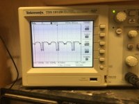
FS Vishay 3020wt
- By Chrisr3521
- Swap Meet
- 4 Replies
I've got 50 of these for some reason, don't need this many as trying to cut down on parts.
£1 each plus shipping at cost ( they are currently £5.96 or equivalent in your currency on mouser not including vat )
£1 each plus shipping at cost ( they are currently £5.96 or equivalent in your currency on mouser not including vat )
Attachments
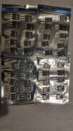
FS Matched 12P20 and 16N25C
- By Chrisr3521
- Swap Meet
- 4 Replies
FS Matched 12P20 and 16N25C fets
More from the job lot I've bought
The 12P20 Matched Quad on the packaging says Matched to 4.854
The 16N25C Matched Quad on the packaging says Matched to 3.812
£30 plus postage tracked and signed for at cost anywhere in the world
More from the job lot I've bought
The 12P20 Matched Quad on the packaging says Matched to 4.854
The 16N25C Matched Quad on the packaging says Matched to 3.812
£30 plus postage tracked and signed for at cost anywhere in the world
Attachments
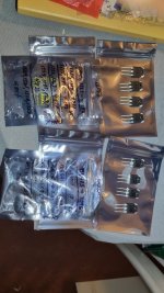
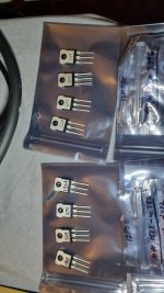
For Sale Toshiba 2SK1530Y + 2SJ201, 4 pairs
- By HelmutHolz
- Swap Meet
- 1 Replies
For Sale: Toshiba 2SK1530Y + 2SJ201, 4 pairs, originals (I guess), I bought them Sept. 2010 from TechDIY LLC.
I don't know, if they are matched and I am able to check that.
I will let them go because time changes as well as projects.
Only the complette set, Europe prefered, 400 € + shipping
I don't know, if they are matched and I am able to check that.
I will let them go because time changes as well as projects.
Only the complette set, Europe prefered, 400 € + shipping
Attachments
Are XOno clones kosher?
I can't see that NP has released the schematics, so I have to wonder if it's OK to build one of the clones available. If it is not allowed/permitted, I will of course stay away from them.
Nice screwdriver bit set from aliexpress
- By rif
- Equipment & Tools
- 9 Replies
Every now and then aliexpress surprises and comes through with something better than junk.
not much to say about it - pictures says it all. Under $30 including shipping.


not much to say about it - pictures says it all. Under $30 including shipping.
Ventilation of soundproofed listening room
- By delapoer
- Room Acoustics & Mods
- 19 Replies
I am in the process of soundproofing a garage to make a listening room. I am interested in ventilating the room and think that a baffle system for an air vent might be the best way to go. Does anyone have any advice about this or can point me at any useful information on the subject? My current thoughts are to a box with inlet and outlet which would be lined with acoustic foam and have partial shelves on alternate sides (also covered with acoustic absorbing foam). Any ideas would be appreciated!
Changed the filters caps on a Carvin FET 450 - resistors blew up
- By esrevinue
- Solid State
- 5 Replies
Hey there!
I purchased a Carvin FET 450 for use with my guitar a couple months ago, and while it initially sounded fine with occasional cutouts, one day it stopped producing sound altogether. Now, I didn't return it because I knew I would have to do some work on this thing and I got a rather good deal on it. I replaced the large bulk caps on it (two 10,000 uf 80v caps) and two of the second largest caps (2,200 uf 25v) and decided to power it on to check my work. I made sure all the quick connects and ribbon cables were inserted exactly as I had found them (obviously before I powered it on). All was fine for a minute - it sounded pretty much as I expected, maybe with a little more hum than was ideal. However, after that period of time, I heard a horrible spitting sound coming from the amplifier and saw smoke starting to leak out of the chassis. I immediately powered it down and opened it back up to observe what had happened. As per the title, some pretty burnt and exploded resistors were there to greet me. Per the markings on the board, R68, 62, 72 and 74 were either beginning to cook or had completely blown up. I excavated all of these to observe the damage, which looked pretty nasty as you can see on the attached images. Some scorching of the board, destroyed traces and what looks like a hole blown through the board, and although I think that was a via that before the resistor above it exploded it and made it larger.
Before I cleaned and removed the blown resistors

Damage on the underside of the board

After I cleaned the board

After looking through the schematic, it's pretty clear the damage occurred only on channel 2, which makes a bit of sense considering that I was only driving one channel of the amp. What doesn't make sense is the fact that it was channel 1 is was driving! Now, before I go ahead and repair the damage, I obviously have to figure out what went wrong. I have a few theories, but this is honestly where my experience with and understanding of electronics ends, which is why I'm coming here for help. My main idea is that someone messed around with the trimmers for the channel bias and the current limiter to match the output of the aging filter caps, (That's P1, 51 and 101) although I can't see how that could draw enough current to blow up what looks like 600 mW carbon film resistors.
If anyone has any ideas as to what went wrong or what I did wrong, it would be very much appreciated! One thing I think I might have done wrong was I think I plugged into and out of channel 2 of the amp, but I don't see how I would have gotten any sound out of it considering I only had the channel one volume turned up and channel two was all the way down.
Sorry for the length of this post, I wanted to be as detailed as I possibly could. If anyone wants any extra information, I'd be happy to provide it.
Thanks in advance!
I purchased a Carvin FET 450 for use with my guitar a couple months ago, and while it initially sounded fine with occasional cutouts, one day it stopped producing sound altogether. Now, I didn't return it because I knew I would have to do some work on this thing and I got a rather good deal on it. I replaced the large bulk caps on it (two 10,000 uf 80v caps) and two of the second largest caps (2,200 uf 25v) and decided to power it on to check my work. I made sure all the quick connects and ribbon cables were inserted exactly as I had found them (obviously before I powered it on). All was fine for a minute - it sounded pretty much as I expected, maybe with a little more hum than was ideal. However, after that period of time, I heard a horrible spitting sound coming from the amplifier and saw smoke starting to leak out of the chassis. I immediately powered it down and opened it back up to observe what had happened. As per the title, some pretty burnt and exploded resistors were there to greet me. Per the markings on the board, R68, 62, 72 and 74 were either beginning to cook or had completely blown up. I excavated all of these to observe the damage, which looked pretty nasty as you can see on the attached images. Some scorching of the board, destroyed traces and what looks like a hole blown through the board, and although I think that was a via that before the resistor above it exploded it and made it larger.
Before I cleaned and removed the blown resistors
Damage on the underside of the board
After I cleaned the board
After looking through the schematic, it's pretty clear the damage occurred only on channel 2, which makes a bit of sense considering that I was only driving one channel of the amp. What doesn't make sense is the fact that it was channel 1 is was driving! Now, before I go ahead and repair the damage, I obviously have to figure out what went wrong. I have a few theories, but this is honestly where my experience with and understanding of electronics ends, which is why I'm coming here for help. My main idea is that someone messed around with the trimmers for the channel bias and the current limiter to match the output of the aging filter caps, (That's P1, 51 and 101) although I can't see how that could draw enough current to blow up what looks like 600 mW carbon film resistors.
If anyone has any ideas as to what went wrong or what I did wrong, it would be very much appreciated! One thing I think I might have done wrong was I think I plugged into and out of channel 2 of the amp, but I don't see how I would have gotten any sound out of it considering I only had the channel one volume turned up and channel two was all the way down.
Sorry for the length of this post, I wanted to be as detailed as I possibly could. If anyone wants any extra information, I'd be happy to provide it.
Thanks in advance!
sound level meter without recalibration
- By arivel
- Equipment & Tools
- 13 Replies
I read that there is a problem with sound level meters, sometimes you have to recalibrate. a possible alternative is to buy a sound level meter combined with a pistonphone but I think the price rises a lot.
so i ask you this, is there a cheap sound level meter that doesn't need to be recalibrated?.
so i ask you this, is there a cheap sound level meter that doesn't need to be recalibrated?.
Thanks To Michael Chua
Thanks to Michael Chua for his well documented Kingfisher III design. I made the bandpass sub taller while keeping the same volume. I went a little more exotic and built a trapezoidal enclosure for the mid/HF drivers. The XO is fairly involved but it sounds great!! Great detail without being overly bright and really tight, fast bass. Thanks to Michael for all of his DIY contributions.
Attachments

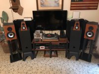
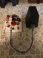
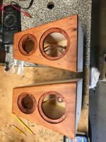
Load more
Projects by fanatics, for fanatics
Get answers and advice for everyone wanting to learn the art of audio.
Join the Community
507,482
Members
7,873,703
Messages