TDA2030 amplifier

I have plenty of TL071CPs lying around, and I am trying to make an amplifier with them. For the input stage, I am using an instrumentation amplifier with a gain of 5. In theory, this should provide pretty high CMRR and could result in a low-noise amplifier.


The input signal comes from my laptop. My power supply is ±12V, and the filter capacitor is not shown in the schematic.


But before I build it, will this work?

Attachments

  • Schematic_WTFAmplifier_2025-05-09.png
    Schematic_WTFAmplifier_2025-05-09.png
    106.3 KB · Views: 155

DIY crossover for replica JBL 4345 horn and tweeter

Hello,

I've a pair of replica JBL 4345 which I've been 4-way actively bi-amping with the DEQX Pre-8.

I'd like to add 2 subwoofers to the mix, and that means I'll have to free up 2 of the 8 channels from the Pre-8.
My idea is to make a passive crossover for the horn (JBL LE 85, 8 Ohm) and tweeter (JBL 077, 8 Ohm), and then run them off of 1 amplifier.

Trouble is I don't have any experience with such activities, so I hope someone here can teach me a thing or two to get started.

What I think I know so far is as follows:
From the JBL 4345 manual they state that the crossover frequency from the horn to the tweeter is at 10kHz, 18dB per octave.
I understand that there are different types of crossovers from 1st to 6th order? They have different names along the way?

After reading around a bit I gather that my crossover needs to be a 3rd order (Due to the 18dB?)

Then I used the link below to calculate what I think is correct:
https://www.diyaudioandvideo.com/Calculator/SpeakerCrossover/

And the result is as follows:
1746692828270.png


In the calculator I had 2 options for a 3rd order, Butterworth and Bessel, what are the differences between these? Which would suit my case the best?


Am I on the right track here? Or is there something I should know about?

How important are the values? Is it okay to be a bit over or under, in case I can't find a capacitor or inductor with the exact value stated?


I hope someone will enlighten me a bit and maybe give some tips if possible.


Best regards,
NavnFugl

Accuton C51-6-286 Pair Unused

I have a pair of these beautiful 2" Ceramic drivers. I mounted one of them in a box, tested it and used it gently for a couple of days. It did not fit the design so now I'm selling them as I don't have any project to put them in and I'm getting rid of some stuff. The driver measured spot on to the advertised specs and sounded great when I briefly listened to music through it (with an active crossover slope of 24db an octave at 800HZ). So you would be getting a brand new pair. I also have the square cell adapters for them, but those were never used. I will throw them in.
https://www.madisoundspeakerstore.c...cuton-cell-c51-6-286-2-ceramic-dome-midrange/
https://www.madisoundspeakerstore.com/midrange/accuton-square-cell-adapter-for-c51/

I'm pricing the pair at $1,200 (plus shipping) but I am more than willing to consider trades for woofers, mid ranges or tweeters so please feel free to ask if you have something around. I tend to use Scanspeak and Purifi stuff.
I am located in Southern California near Temecula
Cheers!

Attachments

  • Accuton both box open.JPG
    Accuton both box open.JPG
    734.5 KB · Views: 166
  • Accuton box with tool.JPG
    Accuton box with tool.JPG
    586 KB · Views: 159
  • Accuton box.JPG
    Accuton box.JPG
    623.9 KB · Views: 156
  • Accuton Seriel number.JPG
    Accuton Seriel number.JPG
    256.1 KB · Views: 158

Recommend a transformer for a DI box for a Guitar

Hey all,

Looking to DIY a DI box for my live electric guitar setup. I have a couple transformers and reading different things for a DI application (10:1, 1:1, etc)...

My setup is a simple analog pedal board ending with a Joyo American Sound. Looking to go direct to a Behringer X18 mixer about 10 feet away via balanced XLR. I am reading I can go direct from Joyo AS to mixer (using a 1/4" to XLR cable), and also reading the DI box would be needed. Looking for advice.

The transformers I have are Sescom MI-52
Specs:
PRIMARY
BLU - YEL 400 ohm (35 ohm dc)
BLK - ORG 400 ohm (32 ohm dc)

SECONDARY
GN - GN/ WT 50k ohm (6k4 dc)

From BLU & BLK tied to YEL & ORG tied is 26 dB @ 1kHz
From YEL to BLK with BLU/ORG tied is 20 dB @ 1kHz

Also have a Sescom MI-8
Specs:

PRIMARY
150 ohm / 600 ohm

SECONDARY
600 ohm

Would either of these work for a DI to mixer?

Open Baffle Analysis

I would like to determine the step frequency of a rear-open baffle speaker. The driver is mounted in a 10"h x 10"w x 12"D enclosure with an open back. Then, I'd like to invoke a sensitivity analysis by changing cabinet dimensions. I'm not sure if it's possible in modeling software, but I would like to compare results against an open driver with no enclosure. The purpose is to demonstrate (via modeling) the effect of a baffle on low-end frequency response. Then, conduct an actual demonstration with an audience.

Paul
  • Like
Reactions: LeifB60

Amplifier based on the Kendall Castor-Perry's Class I output stage

I know I am late for the party, but I wonder if you or anyone did make this amplifier?
After looking at the KCP amplifier previously referred to, I wanted to make one. But I couldn't figure out how to make it complete...
Is the original KCP amp only an 0dB OPS, needing an IPS? With or without global feedback?

Here is what I have done so far:

KPC_skjema.JPG


Original schematic, I think:

media-1174244-class-i-output-stage-fig6.jpg


Thanks for any answers!

🙂 morten
  • Like
Reactions: hbtaudio

Based on Hugh Dean's AKSA 55

A few years ago Destroyer X (with Hugh's permission) published the conceptual schematic of one of Hugh's commercial AKSA 55 kitset products.

Here is the thread for reference:
http://www.diyaudio.com/forums/ever...ugh-thinking-let-us-see-schematics-forum.html

I was learning EAGLE at the time so I drew the schematic and designed a PCB as an exercise. At the time the AKSA 55 was still a commercial product, so I didn't think it was appropriate to publish the PCB. But now, the AKSA 55 is no longer for sale, so I sent the PCB files off to a PCB manufacturer and have now built a few of these amplifiers.

My schematic is a little different from the one that was shown in the reference thread in a couple of ways. I changed a couple of values that were obviously wrong, I used BD139 / BD140 as drivers and I used a BD139 for the VAS. When testing the PCBs I used the recommended transistors mentioned in the quote below.


Here is a quote from Destroyer X's original thread:
  • Differential transistors (Q1, Q2) are matched 2N5401
  • Voltage bias multiplier (Q4) can use BD139
  • Voltage amplifier (Q3) can not inform, a lot of them works there (I used a KSA3505)
  • Drivers (Q5, Q6) are 2SC4793 and 2SA1837
  • Output (Q7, Q8) are 2SC5200 and 2SA1943
  • VBE multiplier transistor (Q4) can be mounted over 2SC5200 (Q7)
  • Bias is 50 mA, and re-adjust again some minutes after first adjustment
  • 100 Ohms resistor connected to Voltage Amplifier transistor is a trimpot, small variable potentiometer
  • If you do not reach the bias current, change R12 value
  • Voltage is plus and minus 36 Volts and power will be 55 Watts RMS over 8 ohms with 0.65 Volts RMS input.

I have actually built one amplifier using BD139 / BD140 transistors and will report on that at a latter date.

Attachments

My Croft super micro schematic

Hi,

I have a couple of questions about my Croft super micro. I tried to create a schematic:

schematic.jpg

It looks similar to the schematics by @Alex M (see here) and also to this one. Please point me to errors in the schematic. There are differences in values (as always with Croft). For example I have 1K8 at R2 and 2K7 at R8 in both channels: the other schematics have 2K7 everywhere. This schematic shows the voltages on top of those resistors: I guess it has to do with the different voltages that sink current through the resistors?

EDIT: schematic updated

Attachments

  • super micro.jpg
    super micro.jpg
    689.8 KB · Views: 182
  • detail.jpg
    detail.jpg
    597.6 KB · Views: 173

Completely wrong DC bias on output stage

Hi everyone,
I'm trying to build this amplifier based on the Sanyo STK465 amplifying module (I attached the originals down below).

And this is my version:
1745403343827.png


I simulated this circuit using LTspice and everything works as I expected. I attached the simulation down below.

The problem is that when I build it in real life the DC bias point of the output stage is not going to 0V DC. It sits close to the positive rail and I can't figure out the reason. I can't proceed further until I get the DC bias point right, so I'm stuck here.

I'm currently using a 10K resistor as the load so i don't fry the output transistors, but the problem persists even with a 10 ohm load. R6 and R7 are there to protect the output transistors as well.

What I tried:
  • I checked the supply rails and they are fine. They come from a dual power supply I built which uses L7812CV and L7912CV linear regulator.
  • I checked the connections a thousand times.
  • Tried to remove all capacitors (excluding the decoupling ones and the compensation capacitor C4) in order to focus on the DC response only.
  • The circuit was originally built on a breadboard. I've now soldered the amplifier on a perf board, while the rest of the circuit (the input section, the output filter, the feedback) is still on the breadboard.
  • I put a 10K potentiometer on the emitter of Q5 and tried to trim it (therefore decreasing the gain of the VAS stage) until I got 0V DC at the output. I couldn't get it to work: as I got closer and closer to zero, the output flipped to the negative rail; I then trimmed the pot on the opposite direction, and the output flipped back to the positive rail. I think this happens because Q5 gets shut completely off, causing the output to swing to the negative rail.

I'm at a loss. Why doesn't the VAS stage bias the Sziklai pairs in the output stage correctly? Do you have any suggestions? Thank you very much for your time and for your help.

Attachments

  • STK465_test_circuit.jpg
    STK465_test_circuit.jpg
    104.8 KB · Views: 92
  • STK465_internal_circuit.jpg
    STK465_internal_circuit.jpg
    90 KB · Views: 95
  • STK_simulation.zip
    STK_simulation.zip
    709.3 KB · Views: 45

Reducing the work on BC1 Bass/Midrange Driver

What is the best way of reducing the Bass - load on a pair of Spender BC1's to protect them from excessive transients when driven at high - ish levels?

Option 1 - A separate Bass Speaker Enclosure with crossover feeding the BC1's, without modification to their crossovers.

Option 2 - A separate Bass Speaker Enclosure, driven by a 405, with filtering at source to split drive between Main Amplifier and 405?

Suggestions for replacement / upgrade of SEAS H254 tweeters?

My two-way active speakers use a Kef B200 SP1014 mid-bass and a Seas H254 tweeter crossing over around 1500Hz. The tweeters have a free-air resonance of 1,400Hz and a recommended operating range of 3k-25kHz, however they use ferrofluid which allows higher power at the lower crossover frequency.

The ferrofluid appears to be drying out as they have developed an 8-dB dip at 10+kHz, so I'm looking for a replacement and given the improvements in driver technology over the years, this seems like an opportunity to upgrade to a driver which can handle the low crossover frequency better and perhaps perform better all round.

According to Falcon Acoustics, who've been very helpful, the Seas H0831-06 is a drop-in replacement, however it has a free-air resonance of 1,200Hz and a recommended operating range of 2-25kHz.

I've looked at a few ranges of tweeters, and found quite a few which may work well, but manufacturers have multiple grades and with their technical data it isn't clear to me whether the improvements with their more expensive offerings are significant.

I'd appreciate suggestions, preferably based on measurements and experience, of good-performing units.

TIA


Seas H254 measurements
2025-05-07 SPL of Seas H254 + 36dB Bessel 1500Hz +3.6dB 2025-05-07 at 08.16.48.png


Speaker response
2025-05-07 Crossover SPL of 36dB Bessel 1500Hz +3.7dB +0mS at 09.15.00.png

For Sale IAN Ucconditioner

Hi!

For sale Ian Canada Ucconditioner 5V MKI & 3.3V MKII boards in perfect condition. 3.3V has never been used, supercapacitors not soldered.
Also for sale 6 uds of BCAP0325 P270 S17 - 325F 2.7V supercapacitors.

Ucconditioner 5V MKI – 40€
Ucconditioner 3.3V MKII – 50€
BCAP0325 P270 S17- 60€ for the pack

best regards,
jm

Attachments

  • 20241110_105706.jpg
    20241110_105706.jpg
    378 KB · Views: 62
  • 20241110_105758.jpg
    20241110_105758.jpg
    272.1 KB · Views: 63
  • 20241110_105854.jpg
    20241110_105854.jpg
    232.8 KB · Views: 65
  • 20241110_105901.jpg
    20241110_105901.jpg
    241.7 KB · Views: 65
  • 20241110_105957.jpg
    20241110_105957.jpg
    348.7 KB · Views: 70

Creation of a MUSES72323 Volume Board for Arduino

Hi there,


since I made already good progress in my modular Arduino based passive pre-Amp project (nearly all stages are in prototyping mode), it is time for me to go to the volume stage.

I want to go with the MUSES72323.

I know that there are already several threats about it, but I did not find one that was really what I am looking for, so I started to dig in by myself.


Goals:
Order a MUSES from Mouser, solder it to a PCB I'll design, control it via Arduino.

Following my idea, I do not want to have anything within my signal way besides the MUSES itself.


I know that the datasheet suggests coupling caps on both sides and output buffers on the output.

But I know that several successful projects (mostly for the MUSES72320) did it without.


But please give me some input!
I know that coupling capacitors are needed to block DC in the signal.
Normally, I expect nearly all source devices to have output coupling capacitors (at least I know that my DIY XONO have some, both of my DAC have it, my old AVR have them (I did not open the new one yet).

So why should I place one in addition here?

Same for the output capacitors.

Most power amps I had on my bench had input coupling capacitors.
And even not, where do we expect the DC to come from?
Or is it known that the MUSES itself tends to create DC?

I simply would prefer to not go, again, into the coupling capacitor rabbit hole + I simply don’t want the pre-amp to change the signal in any way besides the volume.

Also for the buffer, if I want the MUSES to be just a "Volume Pot" I do not see a need.
Specially, when it in fact should just replace a volume pot in an existing chain.


Can you give me some ideas about this?

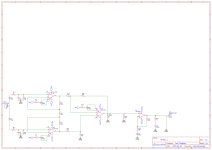
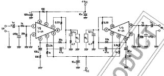
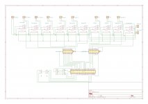
Regarding the schematics, I went through several other projects and build up this schematic:
1737947565560.png


Did I miss anything there or do you think it is good to go?
Do I get it right that GND from the Arduino and GND for the Signal / 15V PSU would be completely separated here?
(I managed so far in the pre-amp that Signal and Digital is completely separated (even there will be one jumper point in case there are issues with the separated GNDs).)
I'm happy for your feedback!

And yes, in case that this works we can talk about sending PCBs to others.

Regards,
Felix

TPA3118, TP2020, TA2024. Which 24VDC Class D amp of today has outclassed these chip amps of yesteryear?

I have one of the 3118 amps in a Lepai 2020A+ (Parts Express) EDIT: No... that amp uses a Tripath TA2020. The 2020TI model (I have both) uses the TPA3118. Regardless, I've used this chip amp quite a lot over the past 4 to 5 years. I like it. It sounds decent and has output protection for my speakers in case an output goes to rail voltage.

But I don't think they even make those chips anymore and I'd bet Class D has improved even a bit more since these were release.

What's the latest trend in Class D 24 volt powered these days?

Tube amp troubleshooting - sympathetic rumbling noises

Hi all, I’ve been enjoying my first DIY amp quite a bit, bringing it out for several gigs, tweaking a few things here and there, and seeing a trajectory of steady improvement with the voicing.
However, there is an issue which I don’t know how to address. I’m hearing an extraneous noise accompanying certain notes, it’s a kind of crunchy rumble. Sometimes I think I’m hearing a distorted sub-tone an octave down.
It only happens on certain notes, and they seem to correlate to mechanical resonance which you can hear if you tap on the tubes or the chassis. The same pitches you hear when doing this, can sometimes get excited into a slow feedback type of noise. The same pitches, when you play them on the guitar, get this extra crunchy whoosh-y rumble added. It doesn’t seem to make a difference how I set the volume on my guitar vs on the amp.
These are behaviors I can notice while playing at home. They’re maybe a bit too subtle to be noticed on a gig scenario. I’m playing louder on gigs, but there’s also other musicians playing and it just gets buried. It would doubtless be a better if the amp didn’t do these things.
Attaching the schematic. V1 is a C3G and yes I’ve got it running at really high gain, but again the offending sound doesn’t seem to care how hard I’m driving the input.
V2 is 6SN7 and this one seems to be the most sensitive, microphonically. The resonance seems to be localized there. I’ve tried swapping in different 6SN7’s, they all act the same. Drivers are 6SL7 and outputs are KT66. Generally the amp sounds pretty good, I’m just pleased it works at all, let alone well enough to play out with.
I hope that someone recognizes the behavior which I’ve described as best I can. Thanks for your thoughts.
Guitar amp rev. 7 page 1.jpeg

Cooling resistors question

Hi,

I am using Ohmite brown devils [200 series] for Cathode bypass and for reducing voltage on the driver valve power supply circuit. The amplifier is a 211 and the power consumed is about 3.5W on each of the cathodes and driver valve circuit uses a resistor that consumes about 9W to drop 300V.

I am able to push air through with some convection and some from low noise fans that move air around the underside of the amplifier near the resistors so they can dissipate some heat BUT they are both placed near some potential complimentary heat sinks (Copper plate 3mm thick and large aluminium plate 19mm thick). Clearly these resistors are designed to be in free space but I can't help but wonder if it would be advantageous to use a direct contact also to the plates to take some additional heat away.

Any more useful thoughts from experienced amplifier builders?

Thanks,

Rich

SEAS 29TTFCD/G H1500-6ohm

A few years ago I purchased some drivers from PartsExpress, and one of the drivers were these Seas H1500 tweeters.
The PE part number was 299-760 and stated "Seas H1500 1" Aluminum", and the sticker on the side shows "29TTFCD/G H 1500-6ohm. Made In Norway".

I can't seem to find any spec sheets on this specific driver though? Does anybody know more about this driver, or have a copy of the spec sheet/pdf file?

Thank you

Placing an object inside a horn

Hi there.

I’ve seen horn loaded designs where there is a large mid range front loaded horn and inside the mouth of that horn there is a high frequency horn (loaded with a compression driver).

My question is, how is the mid range horn designed with an object in its mouth?


I know that wavelengths that are relatively large by comparison with the object will diffract around it and relatively small wavelengths will reflect (in free air, at least). And I realise if the crossover between the mid and high freq horns is at a suitable point, the frequencies that would reflect off the high freq horn would be cut out by the low pass filter on the mid.

However, I don’t know what happens when the object is surrounded by a horn.

Is the horn enlarged and/or shaped to compensate for the volume of the HF horn?

Or does the sound just ‘share’ the air in front of the horn and pass through as if it wasn’t there?

Or something else?

Thanks in advance.

Matching the video in video walls with sound propagation delay in large scale concerts: Are there easy options for it in standard equipment?

In very large scale shows, where the crowd extends to hundreds of meters from the main stage, sound obviously takes a long and noticeable time to reach the crowd, and it becomes a lot delayed relative to the video in large video walls in the stage itself, nothing to do about it in that situation.

But, in even larger scale concerts where additional video walls must be put far from main stage, you could, and perhaps should (in my opinion at least) delay the video in these additional video walls to be in sync with the sound reaching that point of the crowd.

Perhaps this is a rare problem, as usually you don't have such massive crowds where they can't even see the main stage, but this is a reality here in Copacabana, where the crowd extends to 1 kilometer from the main stage, and you need several delay towers plus several video walls so the crowd can see the show.

1746658021482.png


(picture from the Lady Gaga concert in May 3, other concerts here use a similar structure)

The "delay towers" here are themselves a pair of large line arrays with subs (both hanging as a line array behind the mid and treble array and in the ground), and all are, of course, delayed to be in sync with the main stage and with the previous towers.

But, the video and lights in all of those 8 pairs of screens (which are 100 meters from each other) is in sync instead of being delayed to match the sound.

I was in the last screen, sound took over 2 seconds from the main stage, and the video was thus 2 seconds advanced, I only heard what I saw in the video way after.

I think the video should be delayed by the same amount as the audio, so we could feel the video in the closest screen is in sync, or at least almost in sync (as sound itself takes 0.3 s to propagate from one pair of delay towers to the next, so it can't be in sync for everyone anyway, but at least it won't be as gruesome as 2+ seconds).

So, my question is: Is adding a delay in the video on video walls a easy task using the standard equipment used to control them? Like a buffer to store frames and display with a delay?

Sure, if they are to be delayed, so should be the lights over the towers, so the MIDI system should add a delay as well, but this may be not ideal, as it breaks the visual sync in their blinking and changing we can see from far away. But at least would be in sync with the sound.

Precision Power 2150AM Repair

So after 30+ years of sitting in the basement, I pulled my old equipment out to resurrect for my son's car. In a bonehead move while hooking up the 2150AM (Board Rev K) I somehow reversed the input voltage and released some of that magic smoke from the amp. I pulled the amp apart and found the Q50 MOSFET was smoked. I removed that Mosfet and applied power back to the amp. The power light turned on and all components were cool.

In the next bonehead move I decided to see if the amp would still function. I hooked up the input and a 12" to the left channel. Surprisingly the amp was working as it should even without this FET. As I was bragging to my son how they "just dont make em like they use to" something happened and I pulled the power lead. I again touched the power lead to the battery and the power light began blinking then just a bit more smoke came from the FET side of the amp. I removed all 10 FETs from the amp and most are shorted and the others dont seem to test correctly. I had the cover off the back so I am guessing they overheated without being pressed to the heatsink, and the fact it probably is also not intended to work with the missing Mosfet. 🙁

The original ones are labeled as PPI25N06 I cannot seem to find these anywhere. I ordered substitutes from Digikey that seem to be a replacement? FQP30N06FS-ND. Does anyone have any idea if these will work properly with this amp?

https://www.digikey.com/en/products...?s=N4IgTCBcDaIGIEUAKBmADAOTQNjgZQFoMAREAXQF8g

What are the chances anything else was blown during this show? I checked the output transistors, and they all seem to test good.

Thanks for your time! Justin


20250429_201236.jpg

For Sale Dayton PS220-8-8-point-source-full-range speakers

Used pair of Dayton Audio PS220-8 8" Point Source Full-Range speakers. Will ship to lower 48 state, buyer pays. Pm me and I will get a quote.. Great sounding full range drivers solid built. Comes with 3d printed ring baffles asking $150 for the pair.

Attachments

  • IMG_2405.jpeg
    IMG_2405.jpeg
    1.1 MB · Views: 88
  • IMG_2406.jpeg
    IMG_2406.jpeg
    1 MB · Views: 86
  • IMG_2407.jpeg
    IMG_2407.jpeg
    1 MB · Views: 86

DSP Crossover Basics - Phase Alignment Tools

DSP newbie here. I've been spending hours trying to dial in a woofer-to-compression-driver crossover for a large-format soundsystem project, and I've concluded that something just isn't clicking for me. I can't figure out how to get the phases of the two drivers to align for anywhere close to a full octave around my target XO frequency. It seems like there must be some basic tools to deploy or tricks for making this work, but everything I try moves me in the opposite direction. Many google searches hasn't yielded much.

Drivers are a Dayton PA460-8 18" woofer ("W"), and a PRV D2200Ph compression driver ("M") on an 18x10 horn. Target XO point is around 700hz-800hz, I was able to come up with a decent result by crossing the CD at 700hz x 12db, and the woofer at 1khz x 12db, and then delaying the woofer by 0.55ms, but my best case outcome still had a cancellation of around 8-12db at 500hz and a similar one at 1.2khz. I've tried steeper slopes, increasing the target XO point slightly, and even fiddling with all-pass filters but haven't made much progress. It seems to me like the phase curves are just too different at the XO point for any of the tools I am using to make enough of a difference - i.e. flatten the CD curve below 1.5khz or steepen the woofer curve above 500hz. Are these things even possible? Am I screwing up something basic? Any 101-level concepts or tricks to deploy?

Raw phase measurement:
BC Phase Raw 4-15-25.png


12db Filters at 700hz for both drivers:
BC Phase Filtered 4-15-25.png

POWER AMPLIFIER PIONEER M-25

Due to improper installation of my left speaker, the left output burned out. Now I have the problem of not being able to find the MN25 and MP25 germanium transistors, which are internal numbers used only by Pioneer and not a commercial number or model, making them harder to find. Could someone help me with this?

TypeStereo power amplifier
Circuit systemFirst stage differential current mirror load 3-stage Darlington
Parallel push-pull pure complimentary service OCL circuit
Class-AB Operation, DC Amplifier Configuration
Effective output (both channel drive)
8 ohms :120W + 120W (5 Hz to 30 kHz, 0.01% harmonic distortion)
120W + 120W (5 Hz to 80 kHz, Harmonic Distortion Factor 0.05%)
4 ohms :120W + 120W (5 Hz to 20 kHz, 0.02% harmonic distortion)
Harmonic distortion factor (5 Hz to 30 kHz, 8 Ω)Effective power : 0.01%
At 60W output : 0.01%
0.007% at 1W output
Intermodulation distortion factor (50 Hz : 7 kHz = 4 : 1, 8 Ω)Effective power : 0.006%
60W output : 0.005%
0.005% at 1W output
Output Bandwidth (IHF, both channel drives)5 Hz to 45 kHz (Distortion Factor 0.01%)
5 Hz ~ 100 kHz (Distortion Factor 0.05%)
Frequency characteristic5 Hz ~ 200 kHz + 0 -1dB at 1W Output
Input terminalInput : 1V/50k Ω
Output terminal Speaker : 4 Ω ~ 16 Ω
Damping factor100 (20 Hz ~ 20 kHz, 8 Ω)
Signal-to-noise ratio (IHF, A-network, short circuit)120dB
Channel separation1kHz:105dB
100kHz:70dB
Semiconductor usedTransistor : 55
Diode, other : 53 pcs
Power supply voltage100 V, 50Hz/60Hz
Power consumption280W (Electrical Appliance and Material Control Law)
Maximum Power Consumption800W
External dimensionsWidth 420x Height 153x Depth 370 mm
Weight22.5kg

Attachments

  • Pioneer M-25 L-.jpg
    Pioneer M-25 L-.jpg
    146.1 KB · Views: 50
  • Pioneer m-25 R.jpg
    Pioneer m-25 R.jpg
    125.4 KB · Views: 39
  • Pioneer M-25 L.jpg
    Pioneer M-25 L.jpg
    93.4 KB · Views: 42

It’s the Boneman aka bonekrakka I come to bend your earbonez 🤣

My real name is Justin! I was nicknamed Boner by my two older brothers as an adolescent at a ripe old age of 4 years old. Amazingly embarrassing at every critical social interaction. Just happened everyone that heard it found it to be funny and cruel as most young boys are it stuck! I came to the realization I would never escape it and morphed from a BONER “BONG” to correcting people to leave “ER” off and would eccentricity except any form of Bone in pronounceable forms that didn’t sound like I was being referred to as a walking hard on. So now that we have that out of the way……I asked for a sweat modular stereo unit with a Integrated CD player (front vertical loader that you couldn’t snease around less than fifteen feet away from other wise it would skip for longer than this caption) for my 8th birthday with a contribution of about $107 that I had been saving for over a year trying to save enough to buy it myself and couldn’t seem to do obtain it! It also consisted of floor standers a dial tape deck and a topside turntable. Man I thought that tower of frustration was COOL AS HELL. Most people I showed it to (which was everyone that came in my parents house) thought it was cool! 😎 I was the first person in my whole town that had a CD player! Circa 1987! And the audio infatuation was a FULL GO! And will ALWAYS BE!

If I don’t respond don’t take offense!!! I was diagnosed with MS a few years ago and **** is tough sometimes! I most likely will focus my time here on topics like my MEZMERIZE B1 build I am acquisition ING parts for!!!! Boards are here!!! Have about 1000 other projects going but the MEZ is where my heart is 😍curious if anyone has done any recent carnations that are outstanding variations or if the balanced “HOT ROD” is where I should go? I really would like to do mono symmetrical Mez B1’s to enable Tri amplification 🤪any thoughts?

3/4 + 3/4 the strange A1

How can 3/4 plus 3/4 make a wholez?

When two quasi single-ended amplifiers rely on a quarter of the partner. Here is my preliminary finale from the unfortunate thread. It should be noted that the input of the "3/4 + 3/4 = quasi 1 amplifier" would like to be driven with a very low impedance.

HBt.

PS
A test setup will follow.

Attachments

  • new_A1_reboot_v1_1.png
    new_A1_reboot_v1_1.png
    28.1 KB · Views: 439

AMP Volt dB DC meters -- NH USA -- Vintage Original WESTON Model 1011 DC 1.75 Meter Gauge

Message offer in thread of you want the lot.

1) TOTAL payment amount
2) form of payment
3) zip code
https://www.ebay.com/itm/3353294470...2eY4Fe1HR7PA3KKwd8IdbWo6Dw==|tkp:BFBMsN6-ntZl
Vintage Original WESTON Model 1011 DC 1.75 Meter Gauge

Attachments

  • 20250508_161019.jpg
    20250508_161019.jpg
    827.1 KB · Views: 39
  • 20250508_161023.jpg
    20250508_161023.jpg
    859.6 KB · Views: 37

Greetings from Portland, Oregon USA

Hi All,

I'm a Deadhead & Punk from the west coast of the USA. I've lived as far south as La Jolla, CA and as far north as La Conner, WA, but Portland has been my home since 1993. Came to musical life as an Oingo Boingo fan in West LA in the early '80s; by the end of the decade I would have told you my favorite bands were the Dead and the Butthole Surfers. Life was simple!

I had a long technical career and am now involved in an overgrown side hustle of guitar amp repair in Portland. A lot of the work I do is on vintage Fender amps (such a pleasure). I care a lot about getting it right & doing clean work; I'll be coming here to look for insight that combing the Internet hasn't made me feel sure of.

Regards,

Mark

Need help identifying components for Lavry DA11 headphone repair

Hello everyone,
I hope you’re all doing well! I’m reaching out to this wonderful community because I’m in a bit of a pickle with my beloved Lavry DA11 DAC.
The headphone output has stopped working, and upon inspection, I found several burnt components (transistors, resistors, and capacitors) in the headphone section. Unfortunately, the markings on these components are now completely unreadable.
I’ve tried contacting Lavry support several times for component identification, but haven’t had any luck getting a response. As a former Lavry dealer in France (2007-2010), I really love this DAC and would hate to see it end up in a landfill over something potentially fixable.
What I’m looking for:
• If anyone owns a working Lavry DA11 and wouldn’t mind taking clear photos of the headphone circuit components
• Any repair technician who has worked on these units and might recognize the components
• Someone who might have schematics or component list for this section
I’ve attached photos of my unit showing the damaged parts. Any help in identifying these components would be greatly appreciated!
This community has always been amazingly helpful, and I’m grateful for any assistance you can provide.
Thank you in advance,

Attachments

  • IMG_2573.jpeg
    IMG_2573.jpeg
    837.8 KB · Views: 114
  • IMG_2570.jpeg
    IMG_2570.jpeg
    732.9 KB · Views: 102

Add a switch and circuit to change between ultra-linear and triode mode in a Dynavox VR 70 E II.

Hi all....did you know how to d it? Thanks. I just buy this amplifier low cost and good quality, I think, also with the tube preamp TPR-3.
I think it will be improved with this circuit and switch, normally used in others amplifiers as Cayin.. So, thanks for your help.
By the way, my amplifier JCV AX-Z911BK is in the workshop.

8 Litre sub challenge!

Ok so this is technically car audio but I'm looking for any other options for bass in approximately 8l of space(0.3cuft).

Firstly yes I know it's tiny and not to expect a lot. Power is around 2 to 300 wrms which should be more than anything in a box that size can use.

Aiming for 40-80hz in car. Just a little fatness in the bottom end, not window rattling.

My constraints are using an existing enclosure with room for what appears to be a single 6.5 inch driver. I AM ABSOLUTELY open to modding the enclosure with bigger cutouts etc or even glassing in a baffle of some sort.

Enclosure is mounted under a seat and is an odd shape. There is room for a passive radiator by the looks, but at most an 8". Woofer depth is limited to about 125mm (5") and above baffle maybe 3/4 inch including surround excursion.

Really keen to see what driver choices are tucked away. I probably could just find a small enclosure 8 and shoehorn it in (Even an Alpine R 8 says as small as 0.15cuft sealed). Also eyeballing the tangband drivers too. Kenwood shallow 8? Even a pair of 5" subwoofers mounted on the front with the existing hole glasses shut? Pic attached of front side of enclosure, OEM woofer is behind grille on too side. Top is approximately 21.5cm square. Bottom is bigger/longer and front is 22cmx14cm

Open to suggestions for crazy small box drivers🙂

Attachments

  • PXL_20210513_013856455.jpg
    PXL_20210513_013856455.jpg
    979.3 KB · Views: 666

Greetings diyAudio!

My name is Fernando Gonzalez. Some call me "Nano" for short. I am 44 years old. Don't act it, or feel it. I feel like an ignorant child most of the time. But anyway, I just started learning about circuit design about 5 months ago. I started out reading "The Art of Electronics" and watching youtube videos. I mainly focus on building condenser mics and preamps for recording music. I'm not really part of the high-fi world, but I respect it. I will probably ask alot of stupid questions, and stumble around the forum like a drunk old homeless man, begging for bits of knowledge from "real" electronic engineers. You see, I went to college for Psychology. What a waste.. Should have majored in electronic engineering. Anyway, thats it. Thanks for reading.

Measure THD of power amp with sound card - attenuator

Just need a bit of help regarding connecting my sound card to the output of my amp. I have an 8ohm 25watt dummy resistor. The amp works perfectly, however, when the sound card is connected, the dummy resistor starts to burn hot. When replace the resistor with a speaker, you can hear the amp get thrown out as soon as the output is connected to the sound card. The laptop is run off batteries. Sound card is a Behringer uca202. Do I need a DC blocking capacitor, or a massive 500k resistor in series with the sound card input?

So i impulse bought a sub. What would you do with it?

Yeah so i bought a sub on a whim. Its a skar vxf 15 d4.
T/S Parameters
Bl 39.1 n/a
Fs 35.4 Hz
Re Dual 4 Ω
Sd 779.3 cm2
Cms 0.05 mm/N
Mms 384.3 gr
Qes 0.43
Qms 4.78
Qts 0.40
Vas 47.7 L
Nref 0.47%
Xmax 30 mm (one-way)
Sensitvity
88.7 dB
I plan on attempting to build an hroar box for it. So far i have modeled it in a roar box with very nice response from 26hz-80hz. I havent figured out how to translate bp8s function in hornresp to hroar, but i have a good idea what will work without modeling it. Ill post a hornresp response later today. I really have no particular need for this, i just want to build it and see what it does. Ill probably try it in my ht but inevitably it needs to be in an suv or something, so ill probably sell it haha. What would you do with it?
  • Like
Reactions: Booger weldz

Building process - The loudspeaker 1

Greetings to all of you.
After lurking in the shadows of the DIY community I decided to get socially involved in my next project, and present you the building process of THE LOUDSPEAKER 1 of Troels Gravesen.

Objectives:
-Taking the time in design. I truly believe in aesthetics. A nice presented dish is part of the meal, so is with speakers... I enjoy the process of trying and finding a pleasing form etc. Would be great if you could help me with this part of the process. I well know that tastes are different thou there is a common silver lining, I would like to find it with your help!
-going full monty in building process, meaning, giving 110% of my abilitys. I am a young carpenter, so I I have the tools. What I luck is experience...
-making this speaker as if I would make it for a costumer (and a wealthy one as well 🙂 thinking dubai luxury is a good guide line.
-sharing ideas and experiences with you guys, gone are the days of working alone in a basement. This part I am specially excited about!

Inspiration

As for now, the living voice vox project is my inspiration. I foresee disagreement on the aesthetic side but one thing is clear, the vox project is the most perfect, implacable wood working I've seen anywhere! That's exactly what I'm on about.


Disclaimer
So, to summarise, I will take the time with this one so please do not expect quick results.... 🙂 let's make it insane.

Could be cool if you could check other works of mine:
Troels Gravesen DIY loudspeakers - YouTube
And
NEXT4 DIY Loudspeaker Project - YouTube

So, looking forward for you insights. I take all comments as long as it's stays constructive and positive 🙂

Update 8.3.2013- you can now skip the page turning and see the video here:
Login to view embedded media

Raspberry based input selector

I started a project to use Raspberry Zero W to control audio inputs, to turn on/off Tape2Monitor and switch Stereo to mono reproduction.


There are

  • Two turntable connectors (switchable by Rasp)
  • Tuner
  • CD/DVD
  • TV/Cable
  • Tape In
  • Aux
The current status is presented on two 2x16 displays and all is controlled with four push buttons.


I am planning to use ten Takamisawa (Panasonic) RY5W-K relays and two ULN2003AN IC to pass control from Rasp to relays.


Software (Python) is done, all switches are working, displays are showing proper status and corresponding 3.5V from Rasp is sent to two ICs.


I have one dilemma: in order to feed 5V to specific relays (there is going to be up to 4 of them turned on at the time, one by first and up to three by second IC) can I use 5V supply from Rasp (pin 39 from schema) or should I provide additional 5V supply and connect it to pins 9 on both ICs?


Attached is a schematic and I’ll add Python script if anyone is interested.


Thanks,
Marin

Attachments

  • Stampa.jpg
    Stampa.jpg
    447.3 KB · Views: 306

Clon JC2

hello again I put another preamp that is pretty good, the price is something more than the C-3850, but it is still cheap, has good measures something offset 40mv, but once it is with signal there is no noise and much more open sound than the C-3850, I like it more I have tried with several OPA and there is little difference, so I put screenshots, greetings.
2.jpeg
jrc5534 vs muse.jpeg

Muse 03 Yellow Op07 Pink 300khz
NE5534 OP07.jpeg
WhatsApp Image 2024-08-24 at 12.16.54.jpeg

NE5534 vs OP07 300khz
WhatsApp Image 2024-08-24 at 12.19.26.jpeg
WhatsApp Image 2024-08-24 at 12.16.54.jpeg

NE5534 vs Muse 03 300khz
WhatsApp Image 2024-08-24 at 12.20.47.jpeg

as you can see at 100khz there is almost no difference.
Snap_2024.08.26_19h41m59s_002.jpg
Snap_2024.08.26_19h44m38s_003.jpg

be careful with the first one, the one with the potentiometer has a lot of distortion, I'm going to give it to a friend.

Attachments

  • jrc5534 vs muse.jpeg
    jrc5534 vs muse.jpeg
    284.1 KB · Views: 138
  • Like
Reactions: Kleinhorn

rotary band switch cables for Pioneer A-80

Hello, I'm new here on the forum. Let me introduce myself, my name is Rosario, I'm a 33 year old Italian guy.
Since I was a child I have had a passion for hi-fi, especially for vintage hi-fi. I bought a Pioneer A-80 amplifier, unfortunately it has a broken mechanical cable that acts on the speaker selector (speaker selector off A B A+B); after several failed repair attempts, I give up... Can you help me on where to find this spare part? They were often similar, if not the same, on many amplifiers of the time, but the length certainly changes. I've already seen that they've talked about it in this thread, but I don't know if it solved the problem. Thanks in advance 🙂

Attachments

  • 1.jpg
    1.jpg
    19.1 KB · Views: 28
  • 2.jpg
    2.jpg
    802.6 KB · Views: 31
  • 3.jpg
    3.jpg
    610.3 KB · Views: 29
  • 4.jpg
    4.jpg
    465 KB · Views: 35

Recommendation: Good quality cable for headphones

I am going to make up a stereo unbalanced cable to replace some with a break in them for a headphone application. They will ultimately be terminated in 3.5mm jacks.

I am fully on the "cables don't make a difference" train when it comes to audio quality, but I also do know that good quality cables are more robust and generally nicer to handle.

I normally just go with Van Damme + Neutrik/Ream connectors. But I can't find a Van Damme cable that seems suitable for this application. This is the closest I could find:

https://www.van-damme.com/vandamme_product/van-damme-reduced-od-console-cable/

Using the shield as common ground - but I'm not actually that's correct, and also whether having the L & R as a twisted pair is "correct" either. Finally as it's designed for console use, I guess robustness is possibly also not a primary consideration.

So in short, does any one have any recommendations for decent cable to use for headphones.

Semisouth Aleph J?

I have been reading here, there, and everywhere about the different Pass amps that have been made. I have many questions which is evidenced by my random scatter-brained post. MY question for this thread concerns the possibilty of substituting the Semisouth power J-Fet's in the Aleph J layout. THis uninformed question is based on the firstwatt articles including specifically the Sweet Spot. I am a newb, but have plenty of time to ask questions :devily: while simultaneously trying to figure out what the hell i am talking about. If this is doable, i will probably go ahead and buy the pcb's from Peter if they are still available. MY thinking is that this amp would be similar to the J2. I would just do the F5, which is a much easier build according to most, but i have limited funds and think, at least for now, this is what i want.

Question about resonance frequency on WinISD

I don't know how they made WinISD, but I'm aware that it may be possible that using it to simulate designs far enough outside the norm, it could calculate things wrong, if normally insignificant parameters become significant but aren't included in whatever formulas it uses. Kind of like how I can't believe port dimensions are not considered in the SPL graph.

I'm playing around with what happens if weight is added to the driver, and wanted to try to find how the resonance frequency changes, to better understand what's going on. It doesn't always make sense, and I recently found something that really didn't make sense.

Using the impedance graph to judge the resonance frequency in a closed box, adding drivers raises the resonance according to the peak impedance, but if weight is added to the drivers, then adding drivers decreases the resonance. Well, not exactly. Checking it again, I was able to find conditions such that adding weight to 1 driver lowered FS, 2 drivers increased it slightly, then 3 or more drivers decreased it.

It's a faulty formula, right?

Noisy Threshold

I doubt if this can ever be resolved. I had a S500 that had the same noise. Now I have a s550e which sounds amazing but has a slight buzz through speakers when idling just like the S500 had. NOTHING I do gets rid of it. Lifted gnd on power cord. Removed input cables. Switched to balanced input. Can’t hear when playing music but bothers me to hear noise. It was dead silent until the rectifiers were updated and bias pots replaced and adjusted. This must be common in these amps. I’ve read other posts on this. Has anyone ever resolved it?

Millett Hybrid 3B7

This is the Millett Hybrid amp but with Edcor OPTs. You can read about it on his site.
The chassis is steel and rift sawn Sapele.
I am asking $450 (plus shipping), which is basically the cost of parts. I would prefer to sell locally, if possible but I am located in Santa Fe New Mexico, so that might not work out. If you are interested but would require shipping in the US, feel free to message me.

Cheers,

Attachments

  • IMG_2259.jpeg
    IMG_2259.jpeg
    1.5 MB · Views: 129
  • IMG_2260.jpeg
    IMG_2260.jpeg
    1.3 MB · Views: 109
  • IMG_2261.jpeg
    IMG_2261.jpeg
    1.1 MB · Views: 124
  • IMG_2262.jpeg
    IMG_2262.jpeg
    1.2 MB · Views: 125

WMT powered loudspeaker with active crossovers following Philharmonic BMR questions

Hi everyone. I'm finally joining this community which I've learnt a lot from, but I've a few questions that I'm itching to find good answers.
The topic? Powered BMR monitor speakers with a three-way active crossover.

Tweeter: Raal 64-10 (crossed LR4 3400Hz)
Midrange: Tectonic TEBM46C20N-4B BMR 3" (crossed LR4 400Hz)
Woofer: Dayton Epique 180HE-44 7" in a passive radiator sealed box.

Background: I'm really a big fan of Mr. Dennis Murphy's work and wanted to emulate the philharmonic BMR monitors. The extremely wide horizontal dispersion granted by the BMR midrange and raal ribbon is something very appealing and different from any other three way speaker design and made me want to emulate his design. On the way, why not make it an active speaker? Getting past complex passive crossovers means that the amp will see a simple load&reduce back-emf, lower IMD, reduce power loss, and I don't need to deal with crossover complexities. The Xkits active crossover modules are LR4, and the flat performance of the BMR and 64-10 are perfect together.
As for choice of woofer, why these? Why not? Given enough power, these produce decent bass for a 7inch woofer, and measure decently while being compact. And PRs simplify things a lot. For amplification, I'm using two class AB amps for the midrange and tweeter, and class D for bass, but discussion about these will be limited here to focus on the questions.

So my questions are:
1) Given that a rounded side baffle can improve horizontal radiation, is there such a thing as too much rounding? As I know, a more sudden curve can affect longer frequencies more than shorter ones, and so negatively impact horizontal radiation. If this is the case, a more flat baffle might be appropriate.
- There is a simulation for rounded baffles giving very smooth horizontal radiation.
https://www.audiosciencereview.com/.../philharmonic-bmr-speaker-review.14781/page-5

2) Should I stay with the three way WMT design or go for WMTM?
- As much as I love Mr Dennis's BMR monitor design, I'm really tempted to try out his BMR tower design with WMTM using the same BMR and ribbon
- https://philharmonicaudio.com/products/bmr-tower
- Why MTM?
- a single 3" midrange may benefit from an extra one to allow higher SPL capability, lower distortion, and more controlled (albeit narrower) vertical dispersion
- use of a ribbon means a narrow vertical dispersion anyway
- but there's reason for not needing an extra bmr: https://www.erinsaudiocorner.com/loudspeakers/philharmonic_bmr_v2/
- a single BMR exhibits low HD and performs well in the compression test
- A WMTM will look glorious (99% this is the reason). Really, why not? Just go for it?

Thank you, and appreciate any input regarding this.

Hypex UCD700HG and SMPS1200A180 amp build

Hi All

Thought i would post my amp build.

I liked the simplicity of how everything went together.

Only thing needing adjusting was the DC offset (I've drilled a whole in the heatsink inline with the potentiometer so you can easily adjust it)

All in all a fun built and a great sounding amp.

Kept all cables neat and tidy with short runs.

The amp modules are elevated and the heatsinks were modified from an old project to fit.

IMG_20250404_152335.jpg

IMG_20250502_170825.jpg

IMG_20250504_153225.jpg


IMG_20250504_162508.jpg


IMG_20250504_221755.jpg


IMG_20250506_220055.jpg


IMG_20250508_144712.jpg

IMG_20250508_144835.jpg

IMG_20250508_144842.jpg

IMG_20250508_144904.jpg

Attachments

  • IMG_20250503_162038.jpg
    IMG_20250503_162038.jpg
    496.1 KB · Views: 45
  • IMG_20250504_154937.jpg
    IMG_20250504_154937.jpg
    510.6 KB · Views: 49
  • IMG_20250504_155032.jpg
    IMG_20250504_155032.jpg
    382.2 KB · Views: 49
  • IMG_20250504_155721.jpg
    IMG_20250504_155721.jpg
    433.3 KB · Views: 43
  • IMG_20250504_202302.jpg
    IMG_20250504_202302.jpg
    612.3 KB · Views: 41
  • IMG_20250508_144733.jpg
    IMG_20250508_144733.jpg
    447.7 KB · Views: 43
  • IMG_20250508_144820.jpg
    IMG_20250508_144820.jpg
    525.7 KB · Views: 43

MLTL Cabinet for 416-8B

http://www.hostboard.com/cgi-bin/ultimatebb.cgi/ubb/get_topic/f/3729/t/3273

Greets!

Averaged specs used:

Fs' 28.84
Qts' 0.307
Qms' 4.614
Qes' 0.329
Vas' (L) 473.024
Re' 6.442
Le' 1.295
Sd' 856.336
BL' 15.383
Sens' 97.24
Znom' 8

Being fond of the 800 series cab's baffle proportions, an 81" long folded pipe looks good with internal dims of 40.5" H x 28.5" W x 18.75" D including 3/4" divider, so just a hair over the 12 ft^3 limit with external dims of 42" W x 30" W x 20.25" D. Driver down from top front 8.5" and 6" dia. (or other shape = 28.274"^2) x 2" vent on the rear up 17.56" from the bottom for a ~27 Hz Fb.

GM

Attachments

  • altec 416-8b 27 hz folded mltl (kyle - zelgall).gif
    altec 416-8b 27 hz folded mltl (kyle - zelgall).gif
    6.7 KB · Views: 1,521
  • Like
Reactions: Arez

PASS AM part gathering

I'm looking to build an Aleph Mini, currently trying to gather parts to order, for now I have found:

https://www.ebay.co.uk/itm/266392011176?mkevt=1&mkcid=1&mkrid=710-53481-19255-0 - the pcb
https://www.ebay.com/itm/156560013829 - mosfets
alternatively, but I'm not sure if it'd be best - https://www.ebay.com/itm/115126018088?mkcid=16&mkevt=1&mkrid=711-127632-2357-0&ssspo=wGG0QMocRHa

https://a.aliexpress.com/_EIU0SPC - enclosure

I'm also not quite sure about the PSU, what board / transformer should I use, and how to wire the potentiometer.

SPICE Models for 2SB737 / 2SD786 - MC head amp LTspice simulation

Hello, I'm trying to replicate the simulation of Richard Lee's MC head amp from this document:
https://hifisonix.com/wp-content/uploads/2019/06/Richard-Lees-Ultra-MC-Amp.pdf
The simulated circuit uses 2sb737 and 2sd786 transistors but i can't seem to find the device models anywhere. Any help locating them would be greatly appreciated.

Gallien-Krueger MB150E protection circuit issue

Hello,
After using K2 on the potentiometers that were spluttering, I was unpleasantly surprised to see the amp go into safety mode after reassembly.
I checked the supply voltages and found:
+14V at the output of Q13 (LM317) and -14V on Q12 (LM337) for +/-15V ===> correct.
However, I'm reading +25V instead of 32V on R4 and -28V instead of -35V on R7.
R4 and R7 are fuses, and their checked value is consistent with the schematic.
If I disconnect the preamp, I find +60V and -60V across R4 and R7.
I think the problem is with the preamp, but I don't know how to investigate the fault. Any ideas welcome...
Thank you for your help.

All Hitachi Lateral FET amplifier for DIY described by Paul Kemble

Hello

I open these thread for these all Hitachi Lateral & Jfet amplifier.
Here is the circuit & website.
A Paul Kemble web page - Hitachi Fet designs.
Now for these amplifier the mosfets are still available but the JFet must be replaced because they are no longer on the market.
We started a conversation about these amp on the Naim 140 clon from Ebay thread.
We think it is time to keep that threat to Naim clone and open a new for these.
AndrewT advised to dedicate these amp to Borbely...He was famous using fets in his own high-end amplifiers etc.
There is two amplifier circuit. You all welcome if you interested to comment, redesign etc these amplifier.
To the all Hitachi fet I have all the mosfets at hand just need the JFet.
I really would like to give a try (at least test these amp)but not without modifying the front end since those JFet are past now.

Greetings Gabor🙂

Attachments

  • hitmosfet2.gif
    hitmosfet2.gif
    12.1 KB · Views: 7,672
  • Like
Reactions: Stefano

NAD 705 Display issue - NOT BACKLIGHT!

Hi all.
I have recently got my hands on an NAD 705.
It had a backlight issue which I fixed in no time.
But now I notice the display is fading after about 1 second and it's also jittery (some segments sometimes appear randomly?)
Has anyone ever came across this failure?
Is it the LCD itself?
Can it be the LCD Driver? (Sanyo LC7582)

Please help... 🙏

For Sale B&K ST140 Amplifier Boards (EU-Italy)

Hello everyone,
I have for sale pair of DIY finished boards of B&K st 140 amplifier built on the original exactly schematics.
Construction with components of absolute audio quality and definitely superior to the original:
  • Nichicon Fine Gold audio capacitors
  • Nichicon MUSE audio on the signal path (green)
  • MKP bypass capacitors (Polypropylene)
  • Cornell Dubilier silver mica capacitors
  • ORIGINAL HITACHI K135 and J50 final MOSFETS
  • Construction with Cardas tin.
Calibration as service manual 200ma @ 20kHz and zero DC offset (see photo) and absolutely perfect measurements in terms of bias, DC offset and THD (see measurements).
Power supply required dual 60V DC to have the nominal power of 105Watt/channel on 8 ohms.
Sound very well and powerful with NO hum and perfectly stable in temperature and elecrtical parameters.
Big heat sinks is not included.
Price request 80 Euro plus shipping (From ITALY).
Consider that the Hitachi mosfets alone are worth the asking price.
Some pics:

2.JPG1.JPG3.JPG4.JPG5.JPG6.JPG

How to make a whizzer cone

Here I described how to remove a dustcap

https://www.diyaudio.com/community/threads/how-to-remove-a-dustcap.397165/

Now I show an easy way to make a metal whizzer cone or double cone

For a flatter double cone cut one tart alike piece out of an eigth of the round aluminium foil.

For a more steep cut out one fourth of it or more.

The diaphragm is made out of thick aluminum often found for packing coffee

The diaphragm does not look "nice" but is functional. And has a "fuzzy logic" structure. The more it has wrinkles the more it is stable.

As the cone is glued together it has also some damping.

Attachments

  • IMG_20230404_194049.jpg
    IMG_20230404_194049.jpg
    169.9 KB · Views: 364
  • IMG_20230404_194103.jpg
    IMG_20230404_194103.jpg
    337 KB · Views: 347
  • IMG_20230404_194118.jpg
    IMG_20230404_194118.jpg
    394.2 KB · Views: 317
  • IMG_20230404_194422.jpg
    IMG_20230404_194422.jpg
    444.5 KB · Views: 310
  • IMG_20230404_194456.jpg
    IMG_20230404_194456.jpg
    452.4 KB · Views: 324
  • IMG_20230404_194529.jpg
    IMG_20230404_194529.jpg
    439.7 KB · Views: 319
  • IMG_20230404_194539.jpg
    IMG_20230404_194539.jpg
    428.2 KB · Views: 361
  • IMG_20230406_095825.jpg
    IMG_20230406_095825.jpg
    457.9 KB · Views: 378
  • IMG_20230406_095835.jpg
    IMG_20230406_095835.jpg
    494.9 KB · Views: 365

SEAS Full-Range FA22RCZ in MLTL

Back in 2010 i hired Bob Brines to help me with simulation of a MLTL. Many enthusiast in Norway made this construction back then.

This winter (2024-25) I got help from Seas to simulate and measure in the anechoic chamber. IMO their correction filter is very very good.

Here is the driver unit:

https://www.seas.no/index.php?optio...a22rcz&catid=53:prestige-fullrange&Itemid=466

PS! This is only for private use, not commercial!


IMG_6220.jpeg
IMG_6221.jpeg
Projects by fanatics, for fanatics
Get answers and advice for everyone wanting to learn the art of audio.
Join the Community
508,468
Members
7,920,963
Messages

Filter

Forum Statistics

Threads
407,835
Messages
7,920,963
Members
508,468
Latest member
Wheelman