Motivation.
My first three-way started with my wife and one of her friends. No, really.
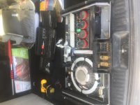
The friend inherited a really nice turntable from another friend's family. Micro Seiki with a nice cartridge, but the turntable speed wasn't constant. So I volunteered to try my hand at fixing it. A little disassembly, cleaning some pots, some calibration, and it was good to go.
But there was a problem. When I tested it with my stereo system, swapping out my old late 70's Technics... it was awesome. I heard things I had never heard before. Dammit, now I need a new turntable & cartridge.
🙄😆
I did that. Just purchased a Fluance with a decent Ortofon cartridge. It sounds great. BUT... the mids are a little harsh, and I can hear some nasty distortion which wasn't evident before - because the rest of the sound is so clean.
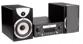
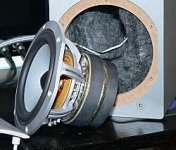
And so the next domino to fall is the speakers. Currently I've got a set of Cambridge Soundworks M80's. They're a 3 way design, but looking at the impedance plot I'm not sure it even has a crossover inside. (And the distortion - meh.)
I built a couple of sets of speakers back about 20 years ago, but have never tackled a 3-way design. But now we have decent simulation software, I've got some decent measurement hardware, the kids are gone, and I'm retired so every week is six Saturdays and a Sunday.
🙂 I've spent some time lurking here, and I think I'm ready to go. And so here's the start of my build thread!
Objectives.
- I want the best set of speakers I can afford. Of course. 😉 I want to be able to listen to Elvis Costello, John Coltrane, Patti Smith, Norah Jones. I want to be able to play the Moody Blues "I'm just a singer (in a rock and roll band)" and hear the vocals on top of the guitar and bass line, without hearing them (vocals) breaking up.
- I would also like to have a design I can tinker with, with well-behaved drivers. I love to learn, and if there's a design that I can start with, model myself, and maybe make some tweaks, now I'm learning something.
- I would like to have a design that can be adapted to a home theater setting - center speakers, satellites. Having a set of similar drivers available which can be easily "matched" is a plus. Having a set that can be dropped into existing crossover designs with a minimum of tweaking is even better.
(BTW my listening room is about 12 x 30, I'm listening across the 12' dimension. There's a hard floor I need to deal with. If the design works really well, there's an upstairs room which might also get a new set of speakers, along with a center channel.)
I was originally thinking of
John Krutke's designs with his ZA14W woofer/midrange, but that appears to be NLA, at least for now. And I'm not sure how much bass I could squeeze out of that design. So, onwards, more reading.
I like Jim Holtz and Curt Campbell's designs, if for no other reason than that they're well documented. Unfortunately, so many of those designs are also NLA. I finally zeroed on on the
Anthology design. It's an MTMWW design which utilizes the Dayton Audio RS225 woofer, the SB Acoustics SB15NRXC30-8 5" midrange, and the Seas 22TFF 3/4" tweeter. Some sims show that I have some hope of using this as a starting point for varied other designs, including a 2-way, a W(T/M)W center channel, or even a simpler TMW.
And so I've got my MiniDSP UMIK measuring microphone, my impedance jig, an oscilloscope (if I need it), taught myself a little bit of VituixCAD, and off we go!
Why mess with a winning combo (the Anthology design)?
Why change what works? The Anthology seems to be well regarded. But, per my points above, this project is not only about building a speaker, but about learning how to build a speaker. Jim & Curt have given enough design details on the crossover and enclosure that I think I can do some tweaking and some learning. And if I fail, I can always go back to their design!
The drivers.
The first thing I did was sim the Anthology design with the stock crossover. OK, works, except that the published design appears to have the tweeter wired out of phase; inverting the phase makes it look great. But... I've read that Jim really likes the SB15CAC woofer for midrange. I subbed the SB15CAC in for the SB15NRX2 (since the NRX is on its way out), and sims beautifully. Better than the NRX2, which has a nasty mode at around 10k that pushes its way into the overall response.
Next step - what about the tweeter? The SB Acoustics SB21RDC (or for that matter, the SB19 and/or SB26) appear to be close to drop-in into the Anthology design, with just a little tweaking, and they seem to be well regarded. An additional advantage is that there's a design for a 3D printed
waveguide for these drivers, giving me even more to play around with/learn about!
For the woofer, I see no reason to vary from the Dayton Audio RS225-8.
The advantage of the mid and woofer is that there are other sizes for each which are pretty easy drop-ins for the crossover design (again, with a few tweaks). For example, one could make a pretty good W(T/M)W center channel with the SB12CAC (little sibling to the SB15) and the RS150 (again, akin to the RS225). Or, substitute the RS270 for the RS225 if I want to turn it up to 11.
The crossover.
For now, the important thing for me is that I have a starting model for a crossover and a decent simulator. The "real"/final crossover design will need to wait until I get the actual drivers in and measure them, then put them in an enclosure in the room.
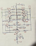
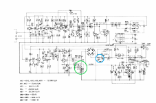
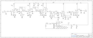
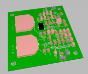
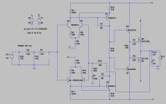
I've got a simulation below. It's second order except for the HF crossover to the mid, which is first order. I've put a "dummy" L-pad in the woofer section to simulate baffle loss since I haven't figured out how to integrate that into the response curve yet.
😆 Once I get the actual drivers, I can better match baffle step with the woofer/mid crossover.
What next?
My work plan is:
- Decide on tentative design, including drivers.
- Put that design out for the diyaudio world for comment - am I missing something? Where I am now!
- Order drivers. I hope to do this next week.
- Measure driver parameters, import into VituixCAD for crossover design.
- Try the tweeter with a 3D printed waveguide and sim that as well - can I improve horizontal response?
- Enclosure design and build (tentative) enclosure.
- Install drivers and play with crossover design/tweaks.
- Tweak for compatibility with listening room.
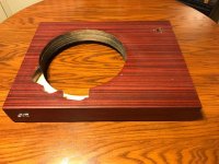
- Build the "real" cabinet, with veneer and a nice finish.
- Listen and enjoy!
- Lather/rinse/repeat.
There's my project, so far. If there's anything I'm missing, or a "OMG, why the **** are you using that driver?", please feel free to chime in! (Especially before I order the drivers!)
Mike (aka Cheesehead)


![20230103_161921[3369].JPG](/community/data/attachments/1051/1051568-faf6ff67a4546dbde34ec317e65af753.jpg?hash=-vb_Z6RUbb)