You are using an out of date browser. It may not display this or other websites correctly.
You should upgrade or use an alternative browser.
You should upgrade or use an alternative browser.
Filters
Show only:
a little guidance please
- By mrorionrob
- Solid State
- 2 Replies
has anyone on here built a 12vdc car amp power supply to use 2 aleph 5 mono diy kits in a car for front speakers yet? if so looking for some rough guidance for power supply specs using smps style toroidal transformer
Need recommendations on 1000uF 50VDC power caps <18mm tall for Soundstream Refrence 604
Hi all, new to the forum here. I am currently getting everything together/setup for installing a sound system in my old W123 Mercedes. I have a McIntosh MX406 HU, Soundstream Reference 604 Amp, and have a variety some old-school MB Quart premium speakers and crossovers incoming. I'm am refurbing everything before install.
Everything works on the Soundstream amp and it is clean inside (except for some discolration around the power chokes, but amp has been bench-tested). However, I am going to be re-capping it. I am having trouble finding replacement caps for the 4 big power caps that are rated at 1000uF and 50VDC. They are currently Nichicon VS-series (cannot find datasheet regarding these anywhere) and 20mm diameter x 15mm height. The big issue is the height! I can go a little taller than 15mm, but not much as there is no clearance beyond ~19mm. I cannot find any caps to fit these specs - all seem to be 20mm, 25mm, or 31.5mm tall which will be too tall. Does anyone know of a current cap that will fit these physical restraints for this purpose?
Thanks,
Allen
Attachments
Heatsink
Hey,
I’m gathering parts for a P3A amplifier, which I intend to use for an active 3 way system. The amps are from ESP https://sound-au.com/project3a.htm
Where can I get some heatsinks?
Websites?
Thanks
I’m gathering parts for a P3A amplifier, which I intend to use for an active 3 way system. The amps are from ESP https://sound-au.com/project3a.htm
Where can I get some heatsinks?
Websites?
Thanks
Unused 12AX7 pins
- By stephe
- Tubes / Valves
- 20 Replies
I only want to use 1/2 of a 12AX7 and was curious what to do with the pins from the unused triode, float or ground them or? TIA
Audio Research phono stage
- By orfeo
- Analogue Source
- 9 Replies
someone can explain me why filament supply of cascode's stage are inverted ? The botton 6922 tube is powered by elevating voltge at 125 volts and the upper at 12 v. it nay be normaly inverted or not ?
Thanks for explaination
Thanks for explaination
Hi from Switzerland
- By boris71
- Introductions
- 4 Replies
Hi there,
Boris from Switzerland. Not necessarily audiophile, but I love music, I love vintage hifi and love working on those old beauties. I prefer vinyl if I have time, but CD or streaming is used as well as the good old reel 2 reel tape.
My current setup (pretty small and packed room - I know)
.jpg")
Boris from Switzerland. Not necessarily audiophile, but I love music, I love vintage hifi and love working on those old beauties. I prefer vinyl if I have time, but CD or streaming is used as well as the good old reel 2 reel tape.
My current setup (pretty small and packed room - I know)
Holco resistors- stock to sell
Hi
I have a lot of Holco resistor H2, H4, H8 to sell all together.
If someone is interested please send a message
Walter
I have a lot of Holco resistor H2, H4, H8 to sell all together.
If someone is interested please send a message
Walter
Cathode Feedback from Output Transformer Secondary Free for All
- By jhstewart9
- Tubes / Valves
- 60 Replies
A thread devoted to the subject of CFB from OPT secondary side to output tube cathode.
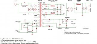
I've moved the 811 SE amp over here for a start. Looking at the operating conditions the claim of 24W audio doesn't make sense.
Running 80 mA plate current from a 600V supply looks like 48W plate dissipation, about the limit given in the RCA TT4 Transmitting Tube Manual.
In Class A Triode efficiency max's out at 25W. That can be pushed somewhat farther but it is no longer Class A & distortion increases.
I tried plotting the Tango 5K loadline on a poorly copied image of 811 plate curves. Trying to flatten the RCA TT4 manual
to stuff into the scanner was a real problem, By using an olde formula found in many RCA tube manuals the loadline never got more than 12W.
I've included some very interesting links, some for the fans of transmitting toobz.
No Sim to measure DF yet, I'll stuff that into the thread later. Time to get outta here for a few hours, 👍
Attachments
-
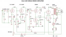 811A 24W SE Amplifier.jpg85.3 KB · Views: 962
 -
 811A SE Amplifier PS.jpg106.7 KB · Views: 672
 -
 811A Plate Curves.jpg57.1 KB · Views: 454
 -
 Tango SE OPTs.jpg72.6 KB · Views: 349
 -
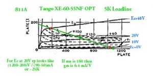 811A Plate Curves & Power Limits A w Captions.jpg22.4 KB · Views: 335
 -
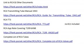 Links to RCA & Other Documents.jpg93.6 KB · Views: 576

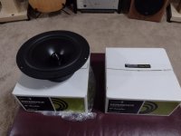
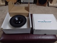
For Sale New pair of Dayton RS225-8 and pair of Wavecor SW182BD01
- By chris mielke
- Swap Meet
- 7 Replies
Have a new pair of Dayton RS225-8 woofers $100pr plus shipping and new unused pair of Wavecor SW182BD01 small subs $150pr plus shipping. Both from projects that went in another direction. Both pairs still in original packaging and never used.
Attachments
KEF 104/2 reference - which ferro fluid?
Hi there,
besides the donut repair and some cosmetic workover (I'll plan to put some new walnut veneer on the cabinets), I want to replace the ferro fluid in the drivers. Now I read somewhere, that there are different ferro fluids available and each one might have a different impact. I have no clue about regarding that topic. Does anybody know what KEF used in the 104/2 and what I have to look for? Or do you guys think it doesn't matter and any ferro fluid will do?
Thanks
Boris
What type of thermal grease needed?
Hi, just had to literally strip down a old Pioneer VSA-E07. While I'm in there I thought best to put new grease on the amp transistors, but, what type of grease do I need?
For Sale Antek AS-3218 300VA transformer + DIYAudio PSU board with Pana 22000uF caps
Antek Transformer and mounting kit + PSU for sale in the UK.
18V duel secondary leads have spade crimps on them, but otherwise transformer as new/ unmarked.
PSU board is populated with 4 large 22000uF, 50V panasonic caps, snubbers, posts, bleed resistors etc. Will also be supplied with 2 rectifier bridges.
Everything you need to build a First Watt +/-24V supply
£150+£10 postage in the UK
Thanks
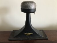
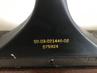
Vintage 3x7 Horn Questions
- By bedrock602
- Multi-Way
- 8 Replies
I have two pair of horns, 1 pair are 8 ohms, the other 16 ohms. Does anyone know who manufactured these and what speakers they would have been
used in?
used in?
Attachments
Help me cook something up with 6S4S
- By Fuling
- Tubes / Valves
- 0 Replies
Hi,
It seems I've been spending too much time on Ebay again, this time resulting in a quad of NOS 6S4S (soviet 6B4G equivalents) being on their way from Hungary.
As I have a slight case of PTSD after chasing hum in a 6B4G SET that I built twenty years I also ordered a pair of Coleman filament regulators.
My speakers have a near zero tolerance for hum...:

At first I reckoned my James JS-6112 HS OPTs (2,5k/3,5k:4/8R) would be a perfect match, then I got some indications that people seem to prefer a less steep loadline for the 6S4S.
That made me think of my old, unused LL1688s that I bought fifteen years ago for a transmitter tube amp project that never happened. According to the datasheet they can be connected as 5K:8R. Absurdly oversized, but wouldn't it be fun...?:

It also seems that 6S4S can appreciate a bit of grid flogging, a.k.a. class A2 operation. This rules out the basic "input triode RC-coupled to output triode"-topology, leaving us with either some form of direct coupled follower or interstage transformer coupling as the only realistic options. I succesfully used high gm cathode followers to push some triode wired 807s into deep class A2 in a recent project, so it would be interesting to try interstage transformers this time. Some digging in my storage room rewarded me with this:

The LL1660 seems to have a bit of a shady reputation as an interstage transformer (but supposedly excellent as line output wired as 4,5:1) and the DCR is a bit on the high side for pushing any real grid current. Those LL1671s seem like a better choice here, although the 50mA airgaps calls for some rather meaty driver tubes.
Speaking of driver tubes, here's a short list of some candidates from the shelf behind me:
As for input tubes, I have a small batch of 2C22 / 7193s that would probably do just fine here, being ~equivalent to 1/2 6SN7 with dual top caps.
My mind gravitates towards something like 2C22 - LL1660 - 6AV5 - LL1671 - 6S4S - LL1688.
Surely an ambitious idea and I would very much like to hear any opinions you might have have about it.
Best regards
Daniel
It seems I've been spending too much time on Ebay again, this time resulting in a quad of NOS 6S4S (soviet 6B4G equivalents) being on their way from Hungary.
As I have a slight case of PTSD after chasing hum in a 6B4G SET that I built twenty years I also ordered a pair of Coleman filament regulators.
My speakers have a near zero tolerance for hum...:
At first I reckoned my James JS-6112 HS OPTs (2,5k/3,5k:4/8R) would be a perfect match, then I got some indications that people seem to prefer a less steep loadline for the 6S4S.
That made me think of my old, unused LL1688s that I bought fifteen years ago for a transmitter tube amp project that never happened. According to the datasheet they can be connected as 5K:8R. Absurdly oversized, but wouldn't it be fun...?:
It also seems that 6S4S can appreciate a bit of grid flogging, a.k.a. class A2 operation. This rules out the basic "input triode RC-coupled to output triode"-topology, leaving us with either some form of direct coupled follower or interstage transformer coupling as the only realistic options. I succesfully used high gm cathode followers to push some triode wired 807s into deep class A2 in a recent project, so it would be interesting to try interstage transformers this time. Some digging in my storage room rewarded me with this:
The LL1660 seems to have a bit of a shady reputation as an interstage transformer (but supposedly excellent as line output wired as 4,5:1) and the DCR is a bit on the high side for pushing any real grid current. Those LL1671s seem like a better choice here, although the 50mA airgaps calls for some rather meaty driver tubes.
Speaking of driver tubes, here's a short list of some candidates from the shelf behind me:
- Sylvania 6AV5GA, the (in)famous 6B4G replacement that has been discussed thoroughly on this forum.
- 4P1L. Adding another DH tube would complicate things quite a bit, and my gut feeling tells me they would prefer ITs with a bit more primary inductance (21H estimated)
- 12B4A. Also a bit of a stretch considering the 50mA airgaps
- 6EW7. Dual triode with one low mu/low Rp section, though I only have 3 and they are rare in Europe.
- 6S19P. Got plenty, not sure how good they are as drivers.
- 807. Not the most linear as triodes, but at least they look quite cool.
- PL36 (25E5). Nice triode curves, slightly inconvenient 25V heaters.
As for input tubes, I have a small batch of 2C22 / 7193s that would probably do just fine here, being ~equivalent to 1/2 6SN7 with dual top caps.
My mind gravitates towards something like 2C22 - LL1660 - 6AV5 - LL1671 - 6S4S - LL1688.
Surely an ambitious idea and I would very much like to hear any opinions you might have have about it.
Best regards
Daniel
CTS 450 and 450S series pots needed, uncommon values
Does anybody have a source for CTS series 450 and 450S pots in uncommon values? I can get 250K and 500K, no problem, but I also need 180K, 1 meg, 100K, and 10K.
Ideally these would be 450S pots with built-in switches but if I can just get the 450 type I can do element swaps.
Yes, I could go to the newer CTS push-pulls with 6 solder terminals but if I do that then I'll have to rebuild the whole front panel wiring/grounding scheme and I'm looking to keep it as original as possible.
Setting up a Chromecast query
- By Moondog55
- Everything Else
- 4 Replies
We need to set up again as the device isn't working well.
It has been pointed up that plugging the Chromecast device directly into the HT amplifier isn't the best idea due to the large number of audio, power and HT cables behind the cabinet and all of the very solid speaker boxes between the device and the Wi-Fi extender.
I just went out and bought a new 5M long HDMI cable and a double female joiner so I could move the dongle somewhere better.
So two questions; is the shortest the distance between the dongle and the extender really important if that distance is less than 4 metres and does the plane of the device matter?
I can figure out a way to fix it to a wall in a vertical orientation or just leave if horizontal on to of the CD and vinyl cupboard, close to the ceiling and with a clear LOS to the extender. So does orientation matter?
What’s this cabinet design called?
- By ElArte
- Full Range
- 27 Replies
Do you know anyone who makes these in the USA?
Labgruppen
- Solid State
- 0 Replies
can somone help me with part number for the labgruppen FP9000 AND FP10000,, I need the audio input board part number,, or if i can get the service manual for the both amplifiers
Can a small hole function like an aperiodic membrane?
- By qObsession
- Car Audio
- 12 Replies
Hey, folks...
I created very small mid-bass enclosures (for 6.5" woofers) in the bottom of my doors (0.07 ft^3). I know that's tiny, but (without getting into ALL the parameters of the system), I didn't need them to play lower than ~120 Hz, so I thought I could "get away with it."
The overall system sounds good, but I couldn't help but wonder whether giving those drivers a little extra "breathing room" might make it sound even better. So, I entertained the idea of making these small, cylindrical enclosures into aperiodic membranes by adding a "vent" to the back of each. There are some good write-ups online for constructing them, so I felt confident.
Before diving in and cutting up what I had, I created a "test enclosure" --a small box with the same volume as the enclosures in my doors. Before creating my first vent, I drilled a small hole (0.5" diameter) into the center of the box, directly center behind the woofer's magnet (just to see what might happen). I stuffed the enclosure full of polyfil and remounted the 6.5" woofer.
TL;DR:
I pressed on the cone, and it (predictably) allowed more excursion, with a gentle puff of air released from the hole. Curious as to how it would sound, I hooked it up and my objective seemed to have been achieved! It boosted output between 90-110 Hz by at least 6dB. And I didn't do any REW measurements (yet), but it sounded nice with music, too! And there was no chuffing from the hole (that was my initial concern).
On a first blush, this "small hole solution" seems to WORK... but am I missing something??
Is it because the enclosure is so small? Because of the frequency band (~90-300 Hz)? Because of the polyfil? Did I just get lucky??
I couldn't find any record anywhere of anyone having done this successfully, so I full expect that I AM missing something!
If anyone has any thoughts about this (specifically, whether the hole can be used in lieu of an aperiodic membrane in certain cases--rather than WHY I would do that instead of a million other 'better' things), I would love to hear from you!
Thanks!!
Tap-in tempo (metronome)
- By ameliabishop
- Everything Else
- 0 Replies
I have adjusted the settings to simulate a metronome (drums only, change drums to click, set Click 1 and Click 2 to the same thing). At this point, I think I have two requests
1) It would be nice if the tap-in tempo function performed a running average of the taps to calculate the average tempo that was being tapped. It occasionally seems that it might be
doing this, but then just one faster tap will make the tempo jump dramatically.
2) It'd also be nice to be able to turn off the extra beats. By setting the time signature to 2/4 I can eliminate half, and by setting the click to 2 and 4 I can reduce them again although
they would happen at the wrong time. t would be nice to see a 1 & 3 option, or a 1-only option so we could get a single metronome click without screwing around with the chart.
Maybe I'm missing something? Maybe setting Click 2 to None (which isn't available of course) would do this?
Pioneer CD skips forward/backward
- By lim0nade
- Digital Source
- 8 Replies
Hi guys. I have a problem with the Pioneer CD player - multi changer side.
Skips forward / backward. I don't find any regularity when and why it does it, every time it's different.
Usually this is solved by lubricating the axis on which the lens moves, but in this case it is something else. I can't find trimmers to adjust focus/tracking gain
which could solve the problem. Optics are KSS-213C model W739
I made a video of the problem: Login to view embedded media Login to view embedded media Login to view embedded media Login to view embedded media Your's advices will be appreciated.
Regards!
Ideas for a diy attempt of a transient shaper (maybe combined with a compressor) as a rack unit ?
- Construction Tips
- 0 Replies
Hey to the forum !
I already went with it to groupdiy but thought the more space covered the better !
Does anyone of you know of a diy project to build a transient shaper ?
Maybe combined with a compressor (but not necessarily so) like the : https://www.tegeler.com/Magnetismus2/Index
There are a few interesting plugins too that could be a inspiration like the : https://www.bozdigitallabs.com/product/transgressor-2/ for example
Maybe there are pcbs around for already existing projects or anybody has a brilliant idea here how it could be made OR already thought about it but it never got reality
Lets see that !
All the best !
Some acoustic guitar body measurements
- By jjasniew
- Instruments and Amps
- 55 Replies
I bought this acoustic guitar on line, used, boy did it sure look nice! Unboxed it, tuned it up and first chord, Uggh. Bright and boxy, just what I dont want to hear. I was wondering why this might be...
So I get out my Pink noise test kit and instead of driving a speaker, I drive a Dayton DAEX25FHE-4 exciter with the little USB powered class D amplifier setup to only play a Pink Noise file on an SD card.
I put a thin gasket foam pad on the exciter VC, to cover the monstrously sticky adhesive that comes with it. Turning the amp volume down to keep the exciter from jumping all over the guitar, I placed it just setting right on the bridge. Clearly driving pink noise into the same spot where the strings actuate the guitar's membrane-o-phone, or "top".
I have a couple older Yamaha G-XX models, which are reputed and to my ears, have a good sound.

It's pretty easy to see the builder's effort to hit a comb at 110, 200, 440 or the "A" note, though it may be off some.

Pretty similar response for the G130, albeit being strung to concert tuning. Apparently all that tension doesnt effect the resonances.
Now let's look at that guitar I didnt particularly care for;

It's clear that the body resonances are shifted higher in the construction of this model. One wouldnt think so by looking at it - it's got a big, deep body. I've read on line that there's pretty much nothing one can do, without risk to the guitar's mechanical integrity, to change this. Better off to sell it and just get something you like.
I have a guitar that's labeled a "parlor" model, a bit smaller in size. One would expect a higher frequency comb pattern. Let's see;

Sharper yet, with a discernable notch even at ~440. My wife and myself doesnt think this guitar sounds particularly good. Hmmm....
I also have a Kala nylon, which I picked up at a yard sale where someone had a whole pile to pick from. Its bridge had torn free, so I epoxied it back in place. It tore off again a couple few years later, so I really laid it on thick for the repair. It's a thin line body, I'd guess all mahogany. I really like the way this one sounds; it's my favorite to play; of course, this particular guitar is unobtanium - there's one steel string variation I can find anywhere.

Clearly this one has resonances flat from the "110" sub-multiple of the A440. So the "A" ends up just on the integrating side of the bandpass, versus the differentiating side. Interesting.
I also have a Yamaha "Silent" nylon string electric and an Ibanez classical, similar in shape to the Yamaha guitars. The Ibanez pulls off a pretty good copy of the Yamaha's "fingerprint";

The silent guitar has signal processing for delay, echo etc and I wondered if they did any analog modeling of a guitar body, you know, to make it sound like an acoustic at the output jack;

Nope - but how interesting!
I believe one could go shopping for guitars with a pink noise analysis kit (battery, SD card playing amp, driver, cell phone for analyzer) and while the use of such may not determine what instrument you should buy, it would certainly help you decide what instrument to bother playing. I wish I had more / access to more instruments, to see what they show for body response. Just setting the transducer upon the bridge is certainly not harmful to the guitar -
I'll try to add to this, as I go through more instruments. I believe the transducer is sensitive enough that it could be driven by a laptop's headphone output directly; it doesnt take much to make an acoustic body speak loud enough to be heard by a measurement mic. I'm excited to try a sine sweep for more precision in establishing the resonances and difference in amplitude between the peaks.
So I get out my Pink noise test kit and instead of driving a speaker, I drive a Dayton DAEX25FHE-4 exciter with the little USB powered class D amplifier setup to only play a Pink Noise file on an SD card.
I put a thin gasket foam pad on the exciter VC, to cover the monstrously sticky adhesive that comes with it. Turning the amp volume down to keep the exciter from jumping all over the guitar, I placed it just setting right on the bridge. Clearly driving pink noise into the same spot where the strings actuate the guitar's membrane-o-phone, or "top".
I have a couple older Yamaha G-XX models, which are reputed and to my ears, have a good sound.
It's pretty easy to see the builder's effort to hit a comb at 110, 200, 440 or the "A" note, though it may be off some.
Pretty similar response for the G130, albeit being strung to concert tuning. Apparently all that tension doesnt effect the resonances.
Now let's look at that guitar I didnt particularly care for;
It's clear that the body resonances are shifted higher in the construction of this model. One wouldnt think so by looking at it - it's got a big, deep body. I've read on line that there's pretty much nothing one can do, without risk to the guitar's mechanical integrity, to change this. Better off to sell it and just get something you like.
I have a guitar that's labeled a "parlor" model, a bit smaller in size. One would expect a higher frequency comb pattern. Let's see;
Sharper yet, with a discernable notch even at ~440. My wife and myself doesnt think this guitar sounds particularly good. Hmmm....
I also have a Kala nylon, which I picked up at a yard sale where someone had a whole pile to pick from. Its bridge had torn free, so I epoxied it back in place. It tore off again a couple few years later, so I really laid it on thick for the repair. It's a thin line body, I'd guess all mahogany. I really like the way this one sounds; it's my favorite to play; of course, this particular guitar is unobtanium - there's one steel string variation I can find anywhere.
Clearly this one has resonances flat from the "110" sub-multiple of the A440. So the "A" ends up just on the integrating side of the bandpass, versus the differentiating side. Interesting.
I also have a Yamaha "Silent" nylon string electric and an Ibanez classical, similar in shape to the Yamaha guitars. The Ibanez pulls off a pretty good copy of the Yamaha's "fingerprint";
The silent guitar has signal processing for delay, echo etc and I wondered if they did any analog modeling of a guitar body, you know, to make it sound like an acoustic at the output jack;
Nope - but how interesting!
I believe one could go shopping for guitars with a pink noise analysis kit (battery, SD card playing amp, driver, cell phone for analyzer) and while the use of such may not determine what instrument you should buy, it would certainly help you decide what instrument to bother playing. I wish I had more / access to more instruments, to see what they show for body response. Just setting the transducer upon the bridge is certainly not harmful to the guitar -
I'll try to add to this, as I go through more instruments. I believe the transducer is sensitive enough that it could be driven by a laptop's headphone output directly; it doesnt take much to make an acoustic body speak loud enough to be heard by a measurement mic. I'm excited to try a sine sweep for more precision in establishing the resonances and difference in amplitude between the peaks.
Has Anyone Used an LXMini+2 Crossover to Modify a Speaker other than a Linkwitz Speaker?
- Pass Labs
- 0 Replies
I recently bought a LXMini+2 (balanced) crossover at the Linkwitz web store to upgrade my Spendor speakers from passive to active crossover.
My intent was to use the online calculator here: http://doublesecretlabs.com/apps/passxo/ to calculate the needed resistor and capacitor values. But I am not sure that the online calculator is applicable to the LXMini+2. Does the calculator work with the LXMini+2?
Also when you changed from the passive to the active crossover, did you simply calculate then 'plug in' the resistor and capacitor values that would give you the stock factory crossover points? Or was there much more to it than that?
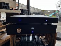
New build: Pass XONO 2019 (RSTaudio)
Hi all,
Over a long period I built a XONO 2019 with boards, documentation and help from RSTaudio (Ralph Stens).
First of all, the boards are very high quality.
Even higher quality is the documentation and preparation done by Ralph. This is unseen!
Also the questions asked about building this project got anwered real fast and professional!
This is a hobby project for him (according himself), which is hard to believe, or his days are 48hrs...
I chose to use DC coupling, so no caps. Ralph sent the boards with the smd components already mounted. I was sure to do some (remote) controlling, so the relays got ordered too, but without the microprocessor designed by Ralph. Allthough I have no doubt this is a very complete en welldesigned control part, initially I was thinking of controlling the phono-pre through the menus of the (diy) preamp, I love to play with arduino-style controllers as well! In the end, I went with standalone arduino-control on arduino boards.
So now my freshly built Xono is 'ON' for 2 weeks nonstop. Even from the beginning it was playing very good.
I am not used to describe sound characteristics.
Also, I can only compare to my previous, cheap-ish but too good for the price, ifi ZEN phono stage.
The Xono is fed by a presumably 'moderate' record player: a refurbished and tweaked Lenco L75/S with standard jelco tonearm (heavier headshell) and new Denon DL103 cartridge.
the ifi ZEN is no comparision for the Xono, with immediately very black backgrounds noticeable which the ifi couldn't do. I never heard before such very black background from a record.
Then there is a drive and speed to the music that could be a relationship between the Lenco's idler drive mechanism and fast electronics, enhancing eachother. That's a quality the IFI had too, in lesser extent. Extension is deep and high, the treble is supersmooth, as extending as my hearing goes. Bass control is tight and deep, much deeper than the ifi could do. The real magic sits in the middle: midrange is so fluent, so musical. Wooden instruments sound wood-ish, brass sounds brass. Percussion is superprecise. Attack and decay are clearly 'visible' elements. Very high resolution, much detail without being analytical at all. The ifi lacked this musicality, this fluentness. The ifi was way more analytical and very bright in comparision.
I have several times the same recordings both on CD, LP and digital. Before Xono, CD really shined. Content was best reproduced through this CD-player even compared with high-resolution digital (and Chord DAC). The record player was since the DL103 on par with digital. Now with the xono, me and friends are really convinced by the sound of Xono, surpassing the CD quality. Not that it's better, is just different with more analog sound, fuller, smoother especially midrange, simply more musical. Then the CD, allthough very good, could be a little clinical, without emotion.
The bad news: I have to buy lots of expensive LP's now!
More bad news: It makes me think about the lesser thing on the turntable: the tonearm.
Does premium cabling do this unit any good? Now it's standard power cabling and Pro-audio XLR cabling (Recordplayer already has chord clearway). If this unit could do even better with better cabling, that would be an upgrade.
System:
==> balanced to ==>
Aleph 5 power amp.
==> audioquest rocket 44 ==>
B&W 802S3 speakers (awaiting Klipsch Forte IV)
I must thank Mr. Ralph Stens, not only for the boards, but this very complete documentation as well.
Software is as follows:
Mechanic is less fun to do: this time I used a part to route a 6mm axle through the panel to make the encoder much better. The display cutout went better on my preamp. No power-on button this time, it is simply always on. The leds are provided with light guides, which is a whole lot better than just ramming a led in a 10mm frontpanel. With blue led it looks gorgeous. The 1U audio enclosure was a bit difficult: had to alter some components and cooling sinks. The arduino is with his usb protruding the backpanel, so updates to software are easy. A simple but quiet 12VDC psu is added for arduino and relays. Designing a pcb of my own with atmega328p is practically not possible for me, so I stick with the full arduino boards.
See pics (power source for Aleph5 in first pic background ;-) )


Over a long period I built a XONO 2019 with boards, documentation and help from RSTaudio (Ralph Stens).
First of all, the boards are very high quality.
Even higher quality is the documentation and preparation done by Ralph. This is unseen!
Also the questions asked about building this project got anwered real fast and professional!
This is a hobby project for him (according himself), which is hard to believe, or his days are 48hrs...
I chose to use DC coupling, so no caps. Ralph sent the boards with the smd components already mounted. I was sure to do some (remote) controlling, so the relays got ordered too, but without the microprocessor designed by Ralph. Allthough I have no doubt this is a very complete en welldesigned control part, initially I was thinking of controlling the phono-pre through the menus of the (diy) preamp, I love to play with arduino-style controllers as well! In the end, I went with standalone arduino-control on arduino boards.
So now my freshly built Xono is 'ON' for 2 weeks nonstop. Even from the beginning it was playing very good.
I am not used to describe sound characteristics.
Also, I can only compare to my previous, cheap-ish but too good for the price, ifi ZEN phono stage.
The Xono is fed by a presumably 'moderate' record player: a refurbished and tweaked Lenco L75/S with standard jelco tonearm (heavier headshell) and new Denon DL103 cartridge.
the ifi ZEN is no comparision for the Xono, with immediately very black backgrounds noticeable which the ifi couldn't do. I never heard before such very black background from a record.
Then there is a drive and speed to the music that could be a relationship between the Lenco's idler drive mechanism and fast electronics, enhancing eachother. That's a quality the IFI had too, in lesser extent. Extension is deep and high, the treble is supersmooth, as extending as my hearing goes. Bass control is tight and deep, much deeper than the ifi could do. The real magic sits in the middle: midrange is so fluent, so musical. Wooden instruments sound wood-ish, brass sounds brass. Percussion is superprecise. Attack and decay are clearly 'visible' elements. Very high resolution, much detail without being analytical at all. The ifi lacked this musicality, this fluentness. The ifi was way more analytical and very bright in comparision.
I have several times the same recordings both on CD, LP and digital. Before Xono, CD really shined. Content was best reproduced through this CD-player even compared with high-resolution digital (and Chord DAC). The record player was since the DL103 on par with digital. Now with the xono, me and friends are really convinced by the sound of Xono, surpassing the CD quality. Not that it's better, is just different with more analog sound, fuller, smoother especially midrange, simply more musical. Then the CD, allthough very good, could be a little clinical, without emotion.
The bad news: I have to buy lots of expensive LP's now!
More bad news: It makes me think about the lesser thing on the turntable: the tonearm.
Does premium cabling do this unit any good? Now it's standard power cabling and Pro-audio XLR cabling (Recordplayer already has chord clearway). If this unit could do even better with better cabling, that would be an upgrade.
System:
- Xono2019 by RSTaudio with modified Lenco L75S and DL103 cartridge (balanced interconnect PRO-audio)
- Marantz UD7007 CD-player (balanced interconnect PRO-audio)
- Roon with RPI on Chord Qutest DAC (unbalanced interconnect Chord clearway) (with sometimes cheap tube stage inbetween, allows for extra gain)
==> balanced to ==>
Aleph 5 power amp.
==> audioquest rocket 44 ==>
B&W 802S3 speakers (awaiting Klipsch Forte IV)
I must thank Mr. Ralph Stens, not only for the boards, but this very complete documentation as well.
Software is as follows:
- Power on: After logo show, device is in mute-state, warmuptime is active 60mins. Display showing minutes countdown every minute, seconds countdown last 2 minutes. Led is slowblinking while warmup. Overrule possible.
- After that, unmute, display shows settings. Display always goes out after 30sec. Turn or press encoder to wake display. Longpress encoder to alter settings, one after the other, with MC/MM showing it's dedicated values. While setting, display does not go sleep, so tweaking sound while listening is easier (allthough no remote control).
- Mute by shortpress, that is often used. Display shows mute, but sleeps after 30sec. Led blinks while sleep.
- Software was fun to do! Compared to the preamp I learned a lot: software is as smooth as can be. No program delays, always running fullspeed. (I am not a professional).
Mechanic is less fun to do: this time I used a part to route a 6mm axle through the panel to make the encoder much better. The display cutout went better on my preamp. No power-on button this time, it is simply always on. The leds are provided with light guides, which is a whole lot better than just ramming a led in a 10mm frontpanel. With blue led it looks gorgeous. The 1U audio enclosure was a bit difficult: had to alter some components and cooling sinks. The arduino is with his usb protruding the backpanel, so updates to software are easy. A simple but quiet 12VDC psu is added for arduino and relays. Designing a pcb of my own with atmega328p is practically not possible for me, so I stick with the full arduino boards.
See pics (power source for Aleph5 in first pic background ;-) )
Attachments
Drivers with phase plugs not completely air tight?
- By Lawnboy
- Full Range
- 1 Replies
I’m finishing up my compact center with two Dayton RS100s. I’ve noticed that even though well sealed, at least I feel well sealed, it isn’t air tight as a driver with a dustcap. Is a little bit of air seeping through the spider around the voice coil and exiting the the space around the phase plug?
Sumo Nine Plus Restore Project-Version A,B,or C??
- By shroaman42
- Solid State
- 0 Replies
Hello,
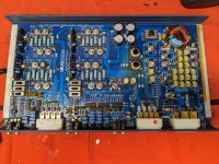
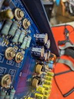
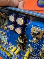
I am beginning a restoration project(one of my first, I'm still very new at this) on a Sumo Nine Plus and need some advice as to which version I should build. It doesn't help that the boards are not matched. One is Rev A, the other is Rev B, although at first glace they look to both match. Some pictures attached. I read a lot of Sumo threads on here, and it looks to be unclear whether the unmatched boards came from the factory of if they are repair jobs, but it seems that this is not the only unit out there like it. Any help with these questions will be greatly appreciated:
-Do the transistors look stock?
-Does anyone have schematics for REV. A and REV B? I have Rev. C.
-Is there a schematic for the power filter and rectification board on top of the transformer?
Thank you!
Jared
The Hundred-Buck Amp Challenge
- By bst
- Instruments and Amps
- 2202 Replies
UPDATE:
Since this thread had pretty much run its course, the rules were loosened in early 2016:
Nobody is enforcing the rules any more. This thread was about making a playable guitar amp for a budget of $100. Unless anybody cares, maybe it should now be about an amp you would really want to use for minimum $$$$. Several good ideas were spawned here and a few amps were made. How many of those amps still get used?
Back then, several compromises were made in our designs to fit the budget. Now that we aren't constrained, we can use the parts we like to get the tone we want...Bring on the 12AX7's and the real OPT's, if that's what works. Anyone and everyone is welcome to play along...rules, we ain't got no stinkin rules!
Try to keep the drama to a minimum.....We all realize that not everybody had the same definition of "tube amp". So what! If you don't like my amp, don't build one. If you have a better idea, post it!
tubelab.com
------------------------------------------------------------------------------------------------------------------------------
This challenge was spun off from another thread here: http://www.diyaudio.com/forums/tubes-valves/190449-need-recommendations-diy-small-guitar-amp.html
The challenge is to build a low-powered practice amp for electric guitar. Power output should be in the range of 2-5 watts. The amplifier project need not include a cabinet or speaker.
Total cost of the completed amplifier is not to exceed US $100 ( or equivalent value in non-US currency).
The power supply section can be solid state, but the signal stages must be all tube. Semiconductors may be used for biasing, current control, etc.
The amplifier must be reasonably safe. No line-powered (non-isolated) designs will be considered, and proper enclosure of high-voltage circuitry is required.
Parts may be sourced from any outlet available to the general public; the object is to develop an amp that anyone can build in the months to come.
Parts from vendors who have severely limited supplies or short-term discount pricing should not be used.
Suggestions for additions or limitations to the challenge rules will be entertained until June 20th, 2011. At that time, the rules will be 'carved in stone', and added to this thread.
A poll will posted, and challenge participants will be asked to vote on the design they consider best overall. On August 15th, 2011 the winner of the design poll will have the cost of all materials for his/her amplifier reimbursed, up to the amount of $100. In addition, $250 will be donated to diyaudio.com in appreciation for providing this forum.
I think this is going to be a whole lot of fun...
Limited replies to conversations within 1 hours
- Forum Problems & Feedback
- 2 Replies
Hello
Is it normal that there is a limit of 5 replies to conversations within 1 hours? Could not find any information about this limit.
Kind Regards
Phil
Is it normal that there is a limit of 5 replies to conversations within 1 hours? Could not find any information about this limit.
Kind Regards
Phil
Zobel for differential amplifier
- By __BriKs__
- Solid State
- 15 Replies
Hello,
I'm working on a home made amplifier, with a full differential architecture and a single rail voltage.
I use a 24V power supply, so that each speaker terminals are bias to 12V.
I use a kind of counter capacitance load composed of self with a small resistors in parallel (R78//L3 and R77//L4):

My amps presents some instabilities and I took a look on Zobel output network, but I don't know how to design it (values of components) and how to arrange it.
In the example above I connect the traditional 10R (in my schema it's 5 R59) in series with the 100nF (C16) in // with the load (R28).
R78/L3 and R77/L4 are parts of the amp and the speaker is represented by R28.
The other way I can connect is the following:

really I don't know how to choose, even if this will help me with instabilities issue (I'm unstable even with no load).
I understand well the benefice of self with R in // (R78//L3 and R77//L4): when I plot phase with spice I could see the phase and gain margin added by those components but for the other branch (R&C in series) I don't see anything when plotting.. (only a very very few difference@frequency above Mhz).
Also my design is almost full smd, I use for R78 and R77 smd 0805 resistors, from my point of view (power dissipation) that's good but I see some large resistors on a lots of design, don't know why is anybody can light me about that 🙂
I'm working on a home made amplifier, with a full differential architecture and a single rail voltage.
I use a 24V power supply, so that each speaker terminals are bias to 12V.
I use a kind of counter capacitance load composed of self with a small resistors in parallel (R78//L3 and R77//L4):
My amps presents some instabilities and I took a look on Zobel output network, but I don't know how to design it (values of components) and how to arrange it.
In the example above I connect the traditional 10R (in my schema it's 5 R59) in series with the 100nF (C16) in // with the load (R28).
R78/L3 and R77/L4 are parts of the amp and the speaker is represented by R28.
The other way I can connect is the following:
really I don't know how to choose, even if this will help me with instabilities issue (I'm unstable even with no load).
I understand well the benefice of self with R in // (R78//L3 and R77//L4): when I plot phase with spice I could see the phase and gain margin added by those components but for the other branch (R&C in series) I don't see anything when plotting.. (only a very very few difference@frequency above Mhz).
Also my design is almost full smd, I use for R78 and R77 smd 0805 resistors, from my point of view (power dissipation) that's good but I see some large resistors on a lots of design, don't know why is anybody can light me about that 🙂
Electrovoice Regency
- By squarehdca
- Multi-Way
- 3 Replies
Does anyone have the old plans for the Electrovoice Regency boxes . I want to use them as the low frequency base of a 3 way system.
Swapping 6N2P into the "Phrugal Phono Pre" - Mangled Highs - Advice Needed
- By dubadub
- Tubes / Valves
- 0 Replies
Hey guys, some of you may remember my old post on the Shure M65 Phono Pre:
https://www.diyaudio.com/community/...tage-a-tasty-m65-preamp-for-under-200.363607/
It's a good DIY kit that uses a pair of 12AX7 in anode-follower. Some impedance issues with certain amps but good for the price. Here's a schematic of one channel:

Well with the cost of 12AX7s these days, I thought I'd try a build with some 6N2P tubes I got for a song. The regular version heats the tubes with 12.6v on pins 4&5, with 14v coming off the transformer. I had a custom transformer made with a 7v 2a secondary so it delivers 6.3v to pins 4&5. So I built this thing now, and hooked it up to my system, and most of the audio band sounds correct, but the highest frequencies, like cymbal crashes, are gone/mangled, so I'm thinking the "pole" might be in the wrong place now? The b+ for this thing is only 100v, so the tubes are running at the low end of their range, and the load lines for the 12ax7 vs 6n2p are rather different grades when we're this far down the charts... Any thoughts?
thanks!
https://www.diyaudio.com/community/...tage-a-tasty-m65-preamp-for-under-200.363607/
It's a good DIY kit that uses a pair of 12AX7 in anode-follower. Some impedance issues with certain amps but good for the price. Here's a schematic of one channel:
Well with the cost of 12AX7s these days, I thought I'd try a build with some 6N2P tubes I got for a song. The regular version heats the tubes with 12.6v on pins 4&5, with 14v coming off the transformer. I had a custom transformer made with a 7v 2a secondary so it delivers 6.3v to pins 4&5. So I built this thing now, and hooked it up to my system, and most of the audio band sounds correct, but the highest frequencies, like cymbal crashes, are gone/mangled, so I'm thinking the "pole" might be in the wrong place now? The b+ for this thing is only 100v, so the tubes are running at the low end of their range, and the load lines for the 12ax7 vs 6n2p are rather different grades when we're this far down the charts... Any thoughts?
thanks!
Attachments
Philips AG 9016 both ch fade in and out
- By jdg123
- Tubes / Valves
- 17 Replies
I understand some will find it sacrilegious but I’ve been trying to bring bac from the dead this old time favorite, Philips AG 9016. I bought it knowing Someone else had been into it and seeing the electrolytic caps had popped out their internals. I replaced the electrolytic caps and retrofitted RCAs to it, even got it up and running with decent voltages and new tubes… but after a minute or two both channels fade out, then back in, then out…
I then changed the rectifier but to no avail. ‘Any ideas of what to try next? 🧐
I then changed the rectifier but to no avail. ‘Any ideas of what to try next? 🧐
ONKYO A-803 Protection circuit problem?
- By desacercate
- Solid State
- 1 Replies
Hi everyone,
I have a problem with Onkyo A 803, when I got it there was no sound at all, I was investigating and decided to change the selector chip, now we have sound and the slector works but ther is one more issue that I cannot resolve. When I turn the amp on the speakers relay click a few times back and forth as the protection was trying to turn them on but it got constantly disconnected. this usually disappears after a while and the realys stay ON. It looks as if the amplifier warms up things go back to norm. However if I click the DIRECT button here we go again, constantly switching on/off. I have the schematics - it's available on the net, but the schematics is not very clear. The fact that I am a novice in the ¨bussines¨ does not help. I've already restored a couple of amps but have no clue what to do with this one. Any help will be appreciated. TIA
I have a problem with Onkyo A 803, when I got it there was no sound at all, I was investigating and decided to change the selector chip, now we have sound and the slector works but ther is one more issue that I cannot resolve. When I turn the amp on the speakers relay click a few times back and forth as the protection was trying to turn them on but it got constantly disconnected. this usually disappears after a while and the realys stay ON. It looks as if the amplifier warms up things go back to norm. However if I click the DIRECT button here we go again, constantly switching on/off. I have the schematics - it's available on the net, but the schematics is not very clear. The fact that I am a novice in the ¨bussines¨ does not help. I've already restored a couple of amps but have no clue what to do with this one. Any help will be appreciated. TIA
Free Schade PCBs
For the cost of shipping (from Canada) I am giving away my surplus PCBs I used to make my full power
schade amp as seen in the following thread.
50w Single-Ended BAF2015 Schade Enabled
I can also provide the KiCAD files if you find them useful.
Regards,
Dan

schade amp as seen in the following thread.
50w Single-Ended BAF2015 Schade Enabled
I can also provide the KiCAD files if you find them useful.
Regards,
Dan
WTB CDB472 Magnavox
Hi I’m looking for a cdb472. I need a clean nice looking face plate. I have one of these with an ugly face plate that I would like to make look better. Can be a none working unit.
RS225 vs L22RNX/P
- By digitalthor
- Multi-Way
- 40 Replies
Hi all
Here in EU the price are pretty similar. But Seas seems to show their measurement for this driver, in only 21 liters(written in small, under the FR ):
http://www.seas.no/images/stories/prestige/pdfdatasheet/h1252_l22rnx_p_datasheet.pdf
Dayton recommend around 12,5 liters:
https://www.daytonaudio.com/product/104/rs225-8-8-reference-woofer-8-ohm
SB23NRX recommend somewhere between 38-75 liters:
https://www.soundimports.eu/en/sb-acoustics-sb23nrxs45-8.html
I Have 3 way mains and 4 subwoofers and have 12 channels of amplification and DSP for each. So I need midwoofers to blend nicely with subwoofers - around 50 - 500hz.
I would like to build something sleek looking like a Jamo 707i or Dali evidence 870. Everything above around 500hz is handled by an SB MW13TX and SB26ADC in 5" Augerpro waveguide.
Subwoofers are four individual boxes - 2 x 12" SS Discovery( 90 liters ) and 2 x 15" Dayton RS390HF ( 125 liters ) - all closed.
So... are different brands recommendations a bit off? Did they forget to be specific about the Q of a given volume? Because I could make the woofer part around 60 liters... just making the design deeper. But it would be nice to know how much artistic freedome I have - given the moderne possibilites from DSP and amplification. Of course keeping in mind, the goal of excelent sound quality.
I should be able to figure this out myself.... but I'm a little baffled - no pun intended 😊
DiyinHK 8 channel Dac
- By maravedis
- Digital Source
- 6 Replies
I'm very tempted by this dac for a multi-channel setup. Has anyone had experience with it? I'm particularly interested in having access to each channels volume control. I'm assuming that I can do this via an arduino but I can't find any info on how to set this up. Any ideas?
Alternatively, the Topping DM7 looks like a good idea = who can help me hack it so I can have access to the individual volume channels? There is a reward waiting....
https://www.diyinhk.com/shop/audio-.../33-dac-xmos_and_dac_pcb/141-fifo_option-null
Alternatively, the Topping DM7 looks like a good idea = who can help me hack it so I can have access to the individual volume channels? There is a reward waiting....
https://www.diyinhk.com/shop/audio-.../33-dac-xmos_and_dac_pcb/141-fifo_option-null
Linn Uphorik serice manual
- By mallikh67
- Analogue Source
- 0 Replies
hi audio folks. looking for service manual of linn uphorik phono stage. its not working so looking to get it rectified with help of schematics
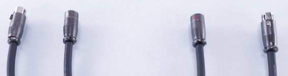
WTB Audiotruth XLR connector Male and female 1 pair each
I am looking for good condition Audiotruth XLR connector Male and female 1 pair each.
Please let me know if anyone have them in stock.
Thanks
Please let me know if anyone have them in stock.
Thanks
Attachments
Quikea diy sound diffusers
- By grosso
- Room Acoustics & Mods
- 4 Replies
Hello guys,
I wanted to share my experience on building few sound diffusors 2 years ago.
We know they can be very expensive from a shop if you want to cover enough, but can also be very ugly if you diy while not so versed in woodworking, like me.
Well I like wood working but it's just very hard to get the clean finish I want, too impatient and I just have basic tools.
In my previous room I had a mix of Decware, ATSacoustics and Giks with great effect.
Money was not a problem at that time, but now the room is twice the size and I really needed a different solution.
Plus I would then be able to define the right frequencies and go a little lower with more depth.
So I wanted to find a good compromise, cheap, fast, easy, while good looking enough.
Re-using an existing and clean looking box was a solution.
But it's not only the box, I also needed to build the wells and fins with what I could find around at a good price (right when wood price started to fly up).
Meaning lumbers and mdf panels with the right dimensions with minimal cuts for the boxes I could find.
Plus I wanted the process to be simple and repeatable, tolerant to human errors, so they would all look and behave alike.
So the lumber cuts/wells dimensions needed to be integer, not too hard to repeat.
Started by looking around all shops for simple box, wood preferably but all kind really.
Then based on theirs size I would calculate the right dimensions for the fins and the wells.
Took a lot of back and forth but I ended with an ikea besta, 60x64x20cm, that exists in black or tan.

It allowed a double symmetric QRD n7 with 38mm wells and 6mm fins with an F low around 350Hz and an F high around 4700Hz, perfect for my OB midranges.
See calc:

Here only half:


Wells from left to right, in mm: 20 box left wall, 12x6 fins + 13x38 wells, 20 box right wall
Depths: 0 - 50 - 200 - 100 - 100 - 200 - 50 - 0 - 50 - 200 - 100 - 100 - 200 - 50 - 0
The 0.8mm added in width were need to include the fins thickness in the wells width calculation.
You will later notice it's not an exact symmetry since side walls/half wells are 20mm and the central one is 50mm with its 2 side fins.
I believe the effect is minimal, and it was just too hard to build without 2 fins on the central one to hold it.
Also once the boxes are stacked there is a little gap between them, so it kind of repeat the width of the central one. Details details...
Price-wise, it was quite some time ago so I don't have all details, but I remember calculating something like 40 euros per diffuser.
I just checked the besta price, now at 35 euros, they were for sure cheaper at that time, I think I remember 20 euros but maybe I’m wrong.
Plus I got more than half in the demo/used corner ready to go.
For the lumbers I had to visit few shops as the real dimensions can differ of their listed spec.
I started with 8 boxes but decided for more after and was lucky enough to find lots with the exact same dimensions as the lumbers I see now are not consistent.
Mdf in 6mm is cheap, especially with the big panel 250/120cm, I didn't try thinner as it was too flimsy.
Big panels are just a pain to cut without proper table but it saved quite a bit I remember.
Process (no pics sorry I didn't think of that):
1 - build the box, without the back panel, doesn't need added glue it's sturdy enough
2 - cut all lumbers to 58cm length, the internal height of the box. Trial and error but 1mm variation is ok. remove the non straight enough ones.
3 - cut mdf into 20x58cm, box height + a little more depth for some to allow glueing the deepest wells at 20cm.
I could have saved even more $ by optimising the cuts here but it was just easier to cut them all at the same dimensions, roughly. Their height is important though of course, needs a 1mm precision, and a clean "front" cut, the back one can be ugly.
4 - dry mount, here I'll try to describe what I did:
Put the box flat on the table, final front facing up.
Then use 13 spare wells (or cut leftover) with the 12 final fins to fit everything first, the wells deep to touch the table, it can be be tight so be careful to not bend the fins, use another lumber to push them.
Then I'd stack more spare wells to define the final depth (I used 25x38, so stacking them would give me the right calculated depth 5/10/20 etc, another place to save money here with thinner lumbers but it was easier)
So row 1: 5 stacked wells + 1 final well gives a final front depth of 5cm, 20-(6x2.5).
Row 2: just 2/3 spare wells to keep the fins in place for now.
Row 3&4: 3 spare wells + 1 final well gives a final front depth of 10cm, 20-(4x2.5).
Etc for other rows.
5- glueing
Once all the stacks are done, I will glue the final wells on top, pushing them to fit tight.
I wasn't sure the glue would be ok on the box surface that is plastic covered, but it was fine it worked.
Once all final wells are glued, put the box carefully on its base, and glue the 2 wells at the back for the deepest depths (row 2&5).
Placed by hand is enough, just make sure you get the 20cm depth in front.
keep drying 1 day.
6 - spare removal
Once all dried you can remove all spares and use them for the next diffuser.
I used to do 1 or 2 a day and it took less than 30min for the last ones.
Only one was not sturdy enough at the end, due to too short fins, added glue from behind fixed it.
Results:


Boxes are solid while still light, can be stacked 3 or more, and moved around safely.
I've just built a base structure as my ground is not flat.
Once all fins are glued they stay in place, but don't push too hard on them.
With the leds the effect is I think pretty cool, lovely at night.
I need to dig-in to find some "before" measurements, I have so many I'm not sure I’ll find the right ones.
Not even sure it will be visible there, but I do prefer with 9 per side for sure, while 4 per side already had an effect.
The room is rectangular, and I use it in its width, so it helped a lot to get back some depth in the soundstage, virtually increased it.
Now I have to work on bass traps...
I wanted to share my experience on building few sound diffusors 2 years ago.
We know they can be very expensive from a shop if you want to cover enough, but can also be very ugly if you diy while not so versed in woodworking, like me.
Well I like wood working but it's just very hard to get the clean finish I want, too impatient and I just have basic tools.
In my previous room I had a mix of Decware, ATSacoustics and Giks with great effect.
Money was not a problem at that time, but now the room is twice the size and I really needed a different solution.
Plus I would then be able to define the right frequencies and go a little lower with more depth.
So I wanted to find a good compromise, cheap, fast, easy, while good looking enough.
Re-using an existing and clean looking box was a solution.
But it's not only the box, I also needed to build the wells and fins with what I could find around at a good price (right when wood price started to fly up).
Meaning lumbers and mdf panels with the right dimensions with minimal cuts for the boxes I could find.
Plus I wanted the process to be simple and repeatable, tolerant to human errors, so they would all look and behave alike.
So the lumber cuts/wells dimensions needed to be integer, not too hard to repeat.
Started by looking around all shops for simple box, wood preferably but all kind really.
Then based on theirs size I would calculate the right dimensions for the fins and the wells.
Took a lot of back and forth but I ended with an ikea besta, 60x64x20cm, that exists in black or tan.
It allowed a double symmetric QRD n7 with 38mm wells and 6mm fins with an F low around 350Hz and an F high around 4700Hz, perfect for my OB midranges.
See calc:
Here only half:
Wells from left to right, in mm: 20 box left wall, 12x6 fins + 13x38 wells, 20 box right wall
Depths: 0 - 50 - 200 - 100 - 100 - 200 - 50 - 0 - 50 - 200 - 100 - 100 - 200 - 50 - 0
The 0.8mm added in width were need to include the fins thickness in the wells width calculation.
You will later notice it's not an exact symmetry since side walls/half wells are 20mm and the central one is 50mm with its 2 side fins.
I believe the effect is minimal, and it was just too hard to build without 2 fins on the central one to hold it.
Also once the boxes are stacked there is a little gap between them, so it kind of repeat the width of the central one. Details details...
Price-wise, it was quite some time ago so I don't have all details, but I remember calculating something like 40 euros per diffuser.
I just checked the besta price, now at 35 euros, they were for sure cheaper at that time, I think I remember 20 euros but maybe I’m wrong.
Plus I got more than half in the demo/used corner ready to go.
For the lumbers I had to visit few shops as the real dimensions can differ of their listed spec.
I started with 8 boxes but decided for more after and was lucky enough to find lots with the exact same dimensions as the lumbers I see now are not consistent.
Mdf in 6mm is cheap, especially with the big panel 250/120cm, I didn't try thinner as it was too flimsy.
Big panels are just a pain to cut without proper table but it saved quite a bit I remember.
Process (no pics sorry I didn't think of that):
1 - build the box, without the back panel, doesn't need added glue it's sturdy enough
2 - cut all lumbers to 58cm length, the internal height of the box. Trial and error but 1mm variation is ok. remove the non straight enough ones.
3 - cut mdf into 20x58cm, box height + a little more depth for some to allow glueing the deepest wells at 20cm.
I could have saved even more $ by optimising the cuts here but it was just easier to cut them all at the same dimensions, roughly. Their height is important though of course, needs a 1mm precision, and a clean "front" cut, the back one can be ugly.
4 - dry mount, here I'll try to describe what I did:
Put the box flat on the table, final front facing up.
Then use 13 spare wells (or cut leftover) with the 12 final fins to fit everything first, the wells deep to touch the table, it can be be tight so be careful to not bend the fins, use another lumber to push them.
Then I'd stack more spare wells to define the final depth (I used 25x38, so stacking them would give me the right calculated depth 5/10/20 etc, another place to save money here with thinner lumbers but it was easier)
So row 1: 5 stacked wells + 1 final well gives a final front depth of 5cm, 20-(6x2.5).
Row 2: just 2/3 spare wells to keep the fins in place for now.
Row 3&4: 3 spare wells + 1 final well gives a final front depth of 10cm, 20-(4x2.5).
Etc for other rows.
5- glueing
Once all the stacks are done, I will glue the final wells on top, pushing them to fit tight.
I wasn't sure the glue would be ok on the box surface that is plastic covered, but it was fine it worked.
Once all final wells are glued, put the box carefully on its base, and glue the 2 wells at the back for the deepest depths (row 2&5).
Placed by hand is enough, just make sure you get the 20cm depth in front.
keep drying 1 day.
6 - spare removal
Once all dried you can remove all spares and use them for the next diffuser.
I used to do 1 or 2 a day and it took less than 30min for the last ones.
Only one was not sturdy enough at the end, due to too short fins, added glue from behind fixed it.
Results:
Boxes are solid while still light, can be stacked 3 or more, and moved around safely.
I've just built a base structure as my ground is not flat.
Once all fins are glued they stay in place, but don't push too hard on them.
With the leds the effect is I think pretty cool, lovely at night.
I need to dig-in to find some "before" measurements, I have so many I'm not sure I’ll find the right ones.
Not even sure it will be visible there, but I do prefer with 9 per side for sure, while 4 per side already had an effect.
The room is rectangular, and I use it in its width, so it helped a lot to get back some depth in the soundstage, virtually increased it.
Now I have to work on bass traps...
UNIVERSAL SPEAKER PROTECTION 2PCB+2RELAYS
- By ronovar
- Group Buys
- 2 Replies
For sale is universal speaker protection that get supply from amplifier PSU, and 1PCB with 1RELAY is enought for STEREO speaker protection.
This protection have the following protections module:
For sale is last 2 sets (1 set is 1PCB & 1RELAY), and interested please write PM with your country so that i can calculate shipping costs...payment is via paypal.


Thanks for your time.
This protection have the following protections module:
- turn ON delay
- AC Power Off (turn speaker off after amplifier power is turned off, so there is no PUFFF in speakers when you turn of amplifier)
- DC Voltage detection on speaker (to protect expensive speakers)
- short circuit protection for output amplifier BJT or MOSFETS stage
- uses high quality relay to maximize sound quality
- it uses professionally made routed PCB that accept RN60D resistors and custom made inductor
- it takes supply from different PSU voltage that feeds audio amplifier so few resistors needs to be calculated to satisfty custom amplifier psu working voltage
For sale is last 2 sets (1 set is 1PCB & 1RELAY), and interested please write PM with your country so that i can calculate shipping costs...payment is via paypal.
Thanks for your time.
Accounts under moderation
- By spirakos
- Forum Problems & Feedback
- 1 Replies
Hello there,
I have just updated my email address, though system obviously thinks that i must be a new member
I can reply to an existing conversation but i cant start a new one
Can you please remove that restriction?
Thanks
I have just updated my email address, though system obviously thinks that i must be a new member
I can reply to an existing conversation but i cant start a new one
Can you please remove that restriction?
Thanks
Rare Dali 700 - upgrading horrible crossovers
I recently got some speakers and possibly the most interesting ones are these Dali 700's. Could not find much information about these tho.
Anyway my very first impressions was that there must be something horribly wrong. Bass was ok, but midrange was quite peaky/one noteish and there was also lack of highs - as well as bad comb filtering. I got heavy listening fatigue after two songs! Whats going on? These are equipped with very high quality drivers: Vifa P25WO, Wifa D75MX and Vifa D25TX tweeters.
It is shame they ruined good drivers with bad crossover design (if you ask me). I took some quick measurements and there it was - same issues were visible. Took the crossovers out and drawed it to my crossover simulator software:

And here are drivers measured, with original crossover:

Pretty much matching my simulation. After that I simulated my own crossover as a starting point for designing new crossovers. Things are now looking much better at least in simulation!

Lower crossover freq is too low here for D75MX, so I finally crossed it at 900Hz / 4000Hz. Also the woofer had rising response toward the 1kHz so had to make some adjustments there too and added Z-network. Here is the measured response from woofer and mid together (some treble leak), good enough at this point.

Finally made some adjustments for mid/high section for a good transition and phase match and oh man these speakers are sounding so sweet! I actually kind of like that Vifa 3" dome midrange, it just makes something right what so ever. It has 1.5 litres enclosure, filled with wool. At this point I just need to listen and listen these to find out if they are good or not 🙂
Response from my listening position (bad room acoustics making bad things for upper bass response). But overall I'm very satisfied now 🙂

And the speakers as they are!

Feel free to give some further advices 🙂
Anyway my very first impressions was that there must be something horribly wrong. Bass was ok, but midrange was quite peaky/one noteish and there was also lack of highs - as well as bad comb filtering. I got heavy listening fatigue after two songs! Whats going on? These are equipped with very high quality drivers: Vifa P25WO, Wifa D75MX and Vifa D25TX tweeters.
It is shame they ruined good drivers with bad crossover design (if you ask me). I took some quick measurements and there it was - same issues were visible. Took the crossovers out and drawed it to my crossover simulator software:
And here are drivers measured, with original crossover:
Pretty much matching my simulation. After that I simulated my own crossover as a starting point for designing new crossovers. Things are now looking much better at least in simulation!
Lower crossover freq is too low here for D75MX, so I finally crossed it at 900Hz / 4000Hz. Also the woofer had rising response toward the 1kHz so had to make some adjustments there too and added Z-network. Here is the measured response from woofer and mid together (some treble leak), good enough at this point.
Finally made some adjustments for mid/high section for a good transition and phase match and oh man these speakers are sounding so sweet! I actually kind of like that Vifa 3" dome midrange, it just makes something right what so ever. It has 1.5 litres enclosure, filled with wool. At this point I just need to listen and listen these to find out if they are good or not 🙂
Response from my listening position (bad room acoustics making bad things for upper bass response). But overall I'm very satisfied now 🙂
And the speakers as they are!
Feel free to give some further advices 🙂
Micromega Stage 6 Cd Player Tray Problems.
- Digital Source
- 7 Replies
Hello everyone,
Wondered if someone could help me troubleshooting a Micromega Stage6 CD player I've got on the bench. Mechanism is a CDM12.2 .
Can't find much info, manuals, schematics, etc on the web.
It is in great condition, but owner (a close friend) said to be unable to detect discs and a "no disc" message was always present.
The thing is once I turned the player on, the CD tray did not even eject. I uncovered the unit and noticed the motor is working apparently fine, belt is in good condition, and gears were fine. Looked like the motor had not power enough to move the tray: If I helped pulling with my hand It eventually opened/closed.
Microswitch is working apparently fine, and everything seemed well lubricated. Could an insufficient lubrication in the gear centre shafts produce this?
The thing is, after some manually opening and closing the tray, the gear that connects to it (see picture) broke some teeths, so now I have another problem. Bought a replacement and it will arrive hopefully in the next few days.
Apart from the tray issue, I decided to address the disc detection problem, placing a disc and completely closing the tray. Player did not read the disc indeed. However, I managed to get it reading fine when the tray is not completely closed, but about half a centimetre open.
What can be causing this?? Microswitch is in the same state both with tray closed and slightly open.
Thank you very much.
Cheers,
Fran
Attachments
Grid leak resistor and grid bias resistor
- By montana
- Tubes / Valves
- 8 Replies
I have DAC which uses tubes and the grid leak resistor and the grid bias resistor are originally Allen Bradley 1W
I have tried to replace them with lower noise vishay cmf55 which like rn60 or rn65
But the sound became worse!!!
Seems since those resistors connected to the ground and carbon resistors are limited in their frequency response....less noise at high frequency enter the tubes or am i wrong?
I have red in diy audio that the recommendation is to go for carbon resistors in those places.
The actual question is there are 2 types of carbon carbon film and carbon composition
Carbon film has a bit less noise than carbon composition.
Do you have any experience with that?
Best regards
Nehoray
RF Filter Placement
- By force of 1/2
- Tubes / Valves
- 13 Replies
Hello,
Having some RFI issues with my 300B amps, that is to say I am "receiving" a particular radio station pretty clearly. It is not super loud, but noticeable in quiet passages for sure.
I moved about a year ago to a place where I am now surrounded by TV and radio towers. This hasn't caused too much trouble except with these 300B amps. (see schematic)
The radio signal is loudest when turning the amps off, or to a lesser extent when turning the amps on. When the voltages and temperatures stabilize, the RFI is at its quietest, though still audible.
I tried cobbling together an RF filter for the signal input of the amps from what I had on hand. I used a 680R series resistor and a 560pF parallel capacitor. This helped a bit, but the radio station is still there.
Due to the fact that the signal gets louder when the rail voltages sink, I was wondering if there might be a better place to put the RF filter than on the input.
Any thoughts on this would be much appreciated.
Regards,
John
Attachments
Open source balanced-input LM3886 design and PCB layout
Hello all,
I've published the design files for my balanced-input chip amp under an open license (CC BY-SA 4.0). The KiCad project files and Gerbers can be found in this GitHub repository. I've also included schematics in PDF (to make them viewable without installing KiCad). Documentation is, unfortunately, non-existent at the moment. I plan to add some documentation as well as BOMs in the future. Any comments/criticisms welcome.
You can see my build using these boards here.
Attachments
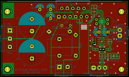
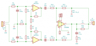
Where can I purchase xover design service ?
- By SoZo
- Software Tools
- 13 Replies
I've been looking for great sounding 3 way speakers but am coming to the realization nothing unless I spend LOTS and up nothing is going to satisfy me. I used to use Madisound for LEAP designs and made a few nice pairs 20 years ago but I see things have changed. I'm again looking to build a nice 3 way for myself with top notch drivers and xover parts, I am very technical and I use REW now for my studio and PA but have to be unpresumptuous and realistic, it would take me LOTS of time to sift through all the software options and learn exactly how to get something close.
Any suggestions would be great.
Thanks,
John
Any suggestions would be great.
Thanks,
John
A Couple capacitor questions.
- By redride27
- Power Supplies
- 0 Replies
I'm in the planning stages of a new build and I wanted to compare some ESR D and Q measurements on the different capacitors I'm using. The results are predictable between the film caps and the electrolytic, but m having trouble understanding.
-the high ESR of the 33uf f&t (they're all new do they need "broken" in?)
-- what ripple current multipliers mean.

(The orange marks are the best numbers for .1uf capacitors) wima mkp stands out.
And if my ripple current in the first filter stage exceeds the datasheet max, do you parallel lower value caps to compensate?

'm building a single ended tube amp and I'm trying to get the best performance out of what I have available.
Thanks for the help in advance.
-
-the high ESR of the 33uf f&t (they're all new do they need "broken" in?)
-- what ripple current multipliers mean.
(The orange marks are the best numbers for .1uf capacitors) wima mkp stands out.
And if my ripple current in the first filter stage exceeds the datasheet max, do you parallel lower value caps to compensate?
'm building a single ended tube amp and I'm trying to get the best performance out of what I have available.
Thanks for the help in advance.
-
-
Locked
Brian Clark G.S.I. Electronic Crossover X-1
For Sale: Brian Clark G.S.I. Electronic Crossover X-1. Two way.
Bought this a while back and did not find any info online for it - I opened her up and saw a sticker saying crossover point is 100hz...
Anyway, no longer need and up she goes... How's $85 + ship?
More pics to be posted later if needed...
Bought this a while back and did not find any info online for it - I opened her up and saw a sticker saying crossover point is 100hz...
Anyway, no longer need and up she goes... How's $85 + ship?
More pics to be posted later if needed...
Attachments
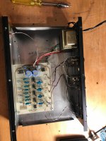
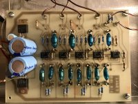
Karlson -XKi style "KUBE 12" for Kappa 12A
I wanted to see what could be done in a little box.
Here's the size comparisons to Greg b's "Karlsonator 12" and Karlson's "L12" cabinets -
(there's almost no damping material in the box other than a few melamine sponges on one side of its floor)
KARLSONATOR 12 bulk = 5.333 CF / 151.05 liters. Fb ~37Hz
KARLSON "K12" = 3.265 CF / 92.48 liters. Fb ~63Hz
KUBE 12 = 2.18 CF / 61.77 liters. Fb ~59Hz
So KUBE 12 is 2/3 the size of a K12 amd 2/5 the size of GegB's Karlsonator 12.
As built by John Lapaire the dimensions are 15" W x 15" D x 16.5" H using 1/2" plywood for the sides/top-bottom and baffle, and 3/4"plywood for the back panel and aperture plate.
I designed it to fit in a particular space and for Eminence's Kappa 12A speaker and to see how small a "K" type might be built for a 12 inch speaker.
It has roughly 28.3 liters back chamber and 11.7 liters front chamber and I used hornresp's series bandpass model to make determinations.
Inner vent area is generous at ~27 sq.in. / 147.2. cm2 and the front aperture could be varied somewhat without much impact upon tuning.
For a little K-type with somewhat smoother response I believe adding a stub or tuned resonator would help matters.
This kritter should make a fun little bass guitar box - or bottom for electronic drumkit.
(I would use it in a -four-way K-stack - 35-80Hz = KUBE18 - 80 - 300Hz = KUBE12 - 300Hz -1500Hz = 8 inch K-midrange - 1500-15000Hz = K-tube.)
BTW, when making this type it could in some instances be useful to cut a "V" notch in the shelf vent per Nexo's patent for a smoother response.
https://patentimages.storage.googleapis.com/6f/8b/29/357e1bb79011ca/US20150222984A1.pdf
Attachments
-
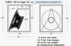 KUBE 12 drawing no handle 1.jpg303.6 KB · Views: 392
 -
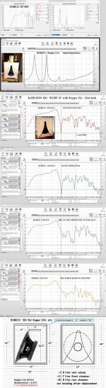 KUBE12 MEASUREMENT vs SIM W 1270.jpg259.8 KB · Views: 304
 -
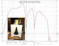 KUBE12 TABLE ON-AXIS 16U 11B W.jpg157 KB · Views: 271
 -
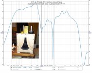 KUBE12 FLOOR MIC 5B 12U W.jpg153.7 KB · Views: 247
 -
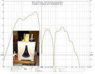 KUBE12 70 OFF H W.jpg149.6 KB · Views: 225
 -
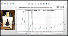 KUBE 12 KAPPA 12A INPUT Z W.jpg165.2 KB · Views: 251
 -
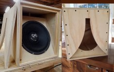 KUBE12 APERTURE PLATE ON.jpg223.9 KB · Views: 305
 -
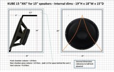 KUBE 15 PLAN DONE.jpg316.5 KB · Views: 266
 -
 Screenshot 2022-01-26 at 14-28-24 1499072939623734451-US20150222984A1 - US20150222984A1 pdf.png46.5 KB · Views: 256
Who's good at adjusting over current window comparator thresholds?
Hi I have a Class D bass amplifier triggering overcurrent detection on certain notes (predominantly D3 = 147Hz) that must be causing some kind of harmonic resonance with other parts of the circuit maybe the output filtering.
Can anybody help me adjust the overcurrent detection thresholds a bit so as to be less sensitive? ... the interaction of the 2x IC's involved IC9 (TS512ID) & IC15 (LM393) is more complicated than I've seen before, maybe it's just the way it's drawn on the schematic.
VDD+ = +5V
VDD- = -5V
Here is the layout:
For Sale Over 100 Speaker Spiders - 6 Sizes
More stuff from storage. See the photos for sizes & shapes. $50 PayPal F&F. US only due to shipping prices.


Cheers, -Casey
Cheers, -Casey
For Sale Eleven (11) 2½", Dual Coil (2Ω per coil) Voice Coils
Bought a dozen of these DVCs years ago from Krenz Electronics and ended up only using one of them. $50 PayPal F&F. US address only due to shipping prices.


Cheers, -Casey
Cheers, -Casey
Sunfire HRS-12
- By RJohns777
- Subwoofers
- 0 Replies
Working on a Sunfire HRS-12. Bridge rectifier was shorted and fuse blown. I replaced the bridge and recapped the power supply board. Replaced fuse and tested. this is what i get on the output to the speaker. Sorry, can't get the scope to trigger on it. But, you can see the wave form. Can't locate a schematic for it. Any help would be appreciated.
Attachments
Help With Identifying this Toiroidal Transformer
I have been trying to source a replacement toroidal transformer for a spare DAC board resurrection. This is for an MHDT Pagoda Balanced DAC.
There are three connectors, which appears to not be typical. I have not been able to find any similar configurations. I also do not have the voltage requirements. The manufacturer is not interested in facilitating my request.
Specifications for the DAC:
Digital Receiver CS8416
D/A converter PCM1704
Frequency response: 20 Hz to 20 kHz (± 2dB) Output impedance: 32 ohms
Output level: 3.0 Vrms
USB input 16, 24 bits 44.1 kHz or 48 kHz, 88.2kHz, 96kHz, 176.4kHz and 192 kHz; drivers required
USB inputs are all in asynchronous operation.
All other inputs (SPDIF) 16, 24 bits 32 kHz up to 192 kHz.
Mains voltage can be adjusted as 220-240VAC or 100-120 VAC (50/60Hz)
Would appreciate any input on how to source a replacement.
Attachments
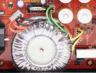
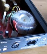
Is there a stereo receiver that has 3 dedicated speaker
- By xyzkum
- Solid State
- 5 Replies
Hey Everyone,
I have two different porches with a pair Klipsch KHO 7's on each.
I also have a pair of old L100 Century's in our living room.
I am currently using a Marantz 2250B for the L100's and my tt and a Sony receiver from the early 90's to run the Klipsch speakers on my porches with a cd player. Everything sounds great but I would like to be able to run everything at the same time with correct ohm levels with great sound.
Is there a stereo receiver that has 3 dedicated speaker outs that someone could recommend? Not a surround type thing but just 3 stereo speaker outs. I have been looking at the Yamaha CR 1020...but didn't know if there were more options. I really don't want to get into a speaker selector type thing.
Thanks,
2 PEC 50K log taper mono volume controls for sale.
I have a few pairs of great sounding PEC 50K log taper potentiometers (volume controls). These were briefly used in a test of different volume controls in a multi channel system. The terminals have been carefully cleaned. They are some of the best all carbon pots you can buy. I would like $40/pair, shipped in the US
Attachments
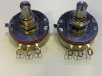

Goldpoint mono 50K stepped attenuators for sale:
Hi. I have a few pairs of Mono Goldpoint 50k ohm stepped attenuators for sale. These were used in a volume control shoot-out in a multi channel system. They are in near mint condition. The input, output and ground connections have been carefully desoldered and cleaned. I would like $125/ pair, shipping in USA included.
Attachments
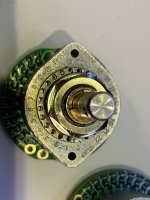
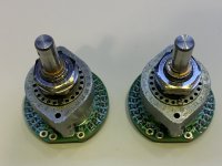
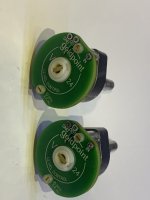
Suggestions for bench-rack for legacy Tek and HP instruments
- By jackinnj
- Equipment & Tools
- 4 Replies
I don't want to get a legacy telephone system ATT/Bell System panel rack, but I have two ganged HP power supplies, two TM5006 with DMM's, PS5010 etc. all with "ears" for racked mounting. In addition, it would be convenient for the 2456 scope to have its own shelf since it is so deep.
Any suggestions?
Any suggestions?
For Sale Tubelab TSE-II 45 Amp with volume control 230V
Tubelab TSE-II 45 amplifier built by myself approximately 18 months ago. I’m an experienced builder, (hi-fi and guitar amps), based in London, UK.
** NOW SOLD **
Valves are a GZ34 rectifier in the power supply with a pair of 5842/417A input valves driving a pair of 45 output valves. The 45’s are DC heated and put out about 2W. Single input connection with a high quality volume attenuator. Housed on a 3mm gold anodised aluminium top from Front Panel Express mounted in a 12mm solid walnut case.
The valves are manually biased, (only required should you change them). It’s a trivial task but you will need a multimeter and a screwdriver. There are test points available and adjustable via holes in the top plate.
Asking price includes the following valves, (these are not the ones in the photos):


** NOW SOLD **
Valves are a GZ34 rectifier in the power supply with a pair of 5842/417A input valves driving a pair of 45 output valves. The 45’s are DC heated and put out about 2W. Single input connection with a high quality volume attenuator. Housed on a 3mm gold anodised aluminium top from Front Panel Express mounted in a 12mm solid walnut case.
The valves are manually biased, (only required should you change them). It’s a trivial task but you will need a multimeter and a screwdriver. There are test points available and adjustable via holes in the top plate.
- Monolith Magnetics SX-1 NanoX nanocrystaline amorphous 5K output transformers, 4/8/16ohm secondaries
- Monolith Magnetics custom power transformer, 230/240V primaries, (no 115V tap)
- Monolith Magnetics custom choke
- Volume control via shunt 23 stepped attenuator, (Takman metal film/Charcroft Z-Foil/Seiden 2 pole 23-way switch)
- Silver wiring (Neotech NEI-1002 on the input, Mundorf silver/gold elsewhere), silver solder
- WBT silver RCA input and speaker output jacks
- Furutech rhodium IEC outlet
- ASC X386S oil filled capacitor in the power supply
- Passive components are a mix of Mundorf/Audio Note capacitors, Amtrans AMRG/Mills/Kiwame resistors
- Dimensions: 44.5cm wide, 34.5cm deep, 22.5cm height
- Weight: 13kg
Asking price includes the following valves, (these are not the ones in the photos):
- 1x JJ GZ34 rectifier
- 2x Western Electric 417A (NOS with low hours)
- 2x RCA 45 (NOS with low hours, ST type)
Bob Cordell Interview: Negative Feedback
- By lumanauw
- Solid State
- 3575 Replies
Mr. Cordell, is there any advantage or disadvantage to have the same amount of feedback for low frequencies (like50hz) and the high frequencies (like 20khz)?
Usually this means to make the OL curve as flat as possible from low to high frequencies. A trick to do this is to put heavy local feedback (emitor resistor) in transistors from differential pair upwards.
Usually this means to make the OL curve as flat as possible from low to high frequencies. A trick to do this is to put heavy local feedback (emitor resistor) in transistors from differential pair upwards.
Current Driven Loudspeakers and Tranconductance Amplifiers
Tranconductance Amplifiers
Recently i have found a Italian site where they made great claims about transconductance amplifiers (amplifiers with very great output impedances)...they claim that they are better suited for driving dinamic speakers,as they say that they are current operated devices.
Wath do you think of this,guys??...current or voltage???...😉
Regards
Jorge
PS: the site ishttp://www.ultrasound-hifi.com/
Troubleshooting a dead TU-8200R
So after somewhat of a haphazard repair where i exchanged the mostfets Q1..Q4 with the incorrect replacements(wrong packaging), around 6 hours of listening later there was a noise in the speakers and silence after that. I tried turning the amp off and waiting a while but nothing. Tried exchanging the tubes as well, still no sound. The amp was idling for an extended period of time (~3 hours) and i was plugging and unplugging headphones (with the volume turned all the way down) when it happened.
So my suspicion is that my mosfets failed in a manner which took the high voltage bridge down with them. These are my voltage measurements, all taken with tubes installed.
1, 2: 0.116, 0.150
3, 4: 0, 0
5, 6: -1, -1
7, 8: -1, -1
9, 10: -1, -1
11, 12: 1, 1
13, 14: -9, -9
15, 16: 0, 0
17, 18: 0, 0
19, 20: 0, 0
21, 22: 0, 0
23, 24: 0, 0
25: 0
26: -31.5
27: -33.8
28: 6.1
29: 6.4
I also measured on the AC side of the HV bridge and i have ~280 or thereabouts VAC, 0VDC on the DC side of that bridge.
Plan now is to order correct mosfet replacements and some new bridges, but wanted to ask if you have any other recommendations for parts which likely let out the magic smoke such as zeners or resistors in the protection circuit? Will check as good as i can visually and with my DMM before i order parts.
2 Midrange driver approach ...?
I see a few designs doing this like Wilson, the Salon 2 etc.... what's the practicality of this approach?
Seems like much more complexity that is not worth it because, take the Scan speak mids for example, looks like even the smaller midrange drivers do not perform much better above 3k.
Seems like much more complexity that is not worth it because, take the Scan speak mids for example, looks like even the smaller midrange drivers do not perform much better above 3k.
Substitute for Vifa C17-WH-09-08
- By Patrice Voo
- Multi-Way
- 5 Replies
Hello,
My 3 years old child just killed a Vifa C17-WH-09-08 driver from my best friend.
Obviously new or 2nd hand Vifa can't be found on the market.
With which other more recent driver can I replace the Vifa driver to keep the same sound quality level?
Thank you in advance for your advice
Patrice
My 3 years old child just killed a Vifa C17-WH-09-08 driver from my best friend.
Obviously new or 2nd hand Vifa can't be found on the market.
With which other more recent driver can I replace the Vifa driver to keep the same sound quality level?
Thank you in advance for your advice
Patrice
FS: Beyma CP750TI 2" Horn Compression Driver New
Selling a Beyma CP750TI 2" Compression Driver New: https://www.ebay.com/itm/275715671688 -- $250
cassette player drive belt size
- By jkojic
- Analogue Source
- 4 Replies
hi- so im replacing a drive belt - non present - ive measured the size with string - what is the reduction percentage please?
Adcom GFP 565 OP-Amp help
- By nhojy
- Analog Line Level
- 88 Replies
Hello everyone. I have a GFP 565 that when the recording and listening switches are put on the same input the woofers move forward and make a pop as I turn up the volume, the same as Gary A. Galo mentioned in his article in Stereophile. I have the service manual for this preamp, but I'm not really great at figuring out schematics. I am decent at soldering, tho and feel I'm capable of fixing this my self, but I'm in need of your help. Could someone tell me which op-amp to replace.
Kind regards
Kind regards
Seas excel or exotic build
Hi all,
It’s my first post here.
I’m looking to build a 2 or 3 way floorstander.
If 2 way it would be the exotic, if 3 it would be seas excel. I can put components together and build good quality cabs but I’m a dunce with working out crossovers. I like the the troels quality, but not his stepped baffles. Has anyone done anything similar in a more conventional or classic design? Can troels electronics be implemented in a slightly different cab? Or maybe a floorstander based around an actual seas based design? Any information would be greatly appreciated. Thanks in advance.
Chevin amp - op amp replacement
- By adrixn
- Solid State
- 2 Replies
Hello,
I am in the process of revising my two a750s and two a2000s, since I have them I have had breakdowns with the bt139 triacs or small dead capacitors (on the 15v power supply).
But I have ignition "junction" noises on one of them, I want to change the op amp to see, but not easy to find..
Do you know what to replace ssm-2131 with? And also op42? (which can be found, but expensive..).
Besides, it's weird, I have an a2000 with op42 even on the front panel.
Do you have an idea of the original configuration? (if there is one).
Thanks!
Adrien
Power supply voltage vs amperage in class D output
This still confuses me just enough to ask, hypothetically, two switching power supplies, 24v 21a output or 36v 14a output, ~500w. Let’s say we have a 160w x 2 amplifier board rated to operate between say, 15v-40v. Let’s say we can tolerate 1% thd and the amp will do ~120wpc at this thd.
This is what I haven’t quite fully absorbed mentally. With a 24v/21a power supply, can this amplifier achieve 160wpc? How about the rated clean-ish 120wpc? Is there truly an overall limitation based on voltage input? Is the abundance of amps at 24v a moot point after some input voltage bottleneck? Is 36v necessary to hit the amps rated output?
There seems to be a formula that predicts this concept, voltage multiplied by 2 divided by resistance? Is it so, that the voltage outputted to the speaker can’t exceed the input voltage minus losses? Resistance looks to affect this maybe?
Let’s just say for fun that we have a 2x400 amplifier board. A power supply with 12 volts and unlimited amperage can only do a couple of watts and after that the amperage matters not?
Proper headers for this card
- By Deadly Sones
- Car Audio
- 7 Replies
Good morning
Just wondering if anyone happens to have a link to Digikey or Mouser for the proper headers for these cards? Or maybe somewhere else?
Thanks in advance!
Just wondering if anyone happens to have a link to Digikey or Mouser for the proper headers for these cards? Or maybe somewhere else?
Thanks in advance!
Attachments
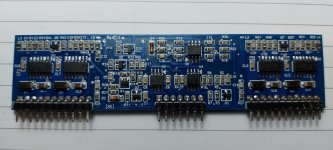
Speaker placement
- By mbrierley
- Room Acoustics & Mods
- 9 Replies
I can see eyes rolling to heaven already. I have a pair of Troels Nomex V1 (2.5 way, 40L, 2x 6.5" mid/bass) front ported in a near perfect listening room area (Cardas defined 12x 16x 10ft). I currently have the speakers positioned almost as near to Cardas definition of perfect placement too, 164cm (64") from rear wall and 78cm (30") from side walls and about 182cm (71") between the speakers and listening position.
BUT, I note some people position waaay closer to walls without losing anything. This has me truly baffled (pardon pun). The majority of member setups I have seen place the speakers far closer to the back wall. Even the Troels TL1 which is a complete beast of a box.
Current placement gives me lots of everything, especially detail. I'm not a fan of bass deep enough to muddy everything else which is my fear of moving the speakers backwards. I know everyones room is different to mine as are their speakers, but if I moved them back a foot, what can I expect (besides deepening bass).
Cheers for looking.
FS tuning, enclosure size, WINISD and DATS...who is right ?
Hi, its been a while last time i posted here
Recently i made a DIY project. i wanted to have speakers like the 4351 from Kenrik's
So i made some with what i had.
I picked up Goldwood GW15PC-4, strictly because the specs on paper was convincing and relatively similar to the JBL 2235h. i know, i know, they are cheap woofers and there isnt much to believe in, but anyway, this is what i had, they where cheap and easy to get.
So
I entered the parameters into WINISD and builded the enclosure accordingly.
Front/back is 1" mdf, sides are multiply 18mm veneer. all braced inside, very strong. glued and screwed. i didnt cheaped on this part.
I followed what win isd told me
about 11ft3 and a tuning FS of 30hz
that made 6x 3" port of about 8.5" long
which is almost the same "close" basic dimensions as a 4350/4351 when compared so in my head i was not far from something that would work
They play loud and clean, it moves tons of bass in the house (powered byt a BGW7000)
But i had some doubts abut the Goldwoods and their published specs. Altough they play tons of bass, i feel that it is not as expected.
Cross over took me 2 year to calculate, test, design and build. lets focus on the bass section plz.
I recently bought a DATS V3. I took the woofers out and promply tested them. Turns out that with broken in woofers, the VAS has almost doubled. published spec is 4.4ft3 and the DATS measures 6.5ft3
I then mesured the sweep impedance to test the FS
it came out as 22hz !!
i know some times a woofer with a high Q can have the enclosure FS tuned below speaker FS...but 22hz i think its quite low
I then decided to shave a bit the ports
i shaved around -2inches on the 6 of them into one enclosure and came with a FS of 25....still far from the WINISD predicted 30hz.
i re-measured many times the internal volume and i am 100% dead sure it is 11.5ft3.
moderate 1" dacron on the walls
picture: measurement of the FS before shaving off the ports. and the speaker enclosure itself.
should i leave them this way ?
am i right to aim at raising a bit the FS to flaten out the frequency response from 30hz and up ?
how come the final FS is so low ?
What should i believe in, the goldwood specs, the DATS V3 ? WINISD ?
thanks for any guidance (or not if you think they are ok like that)
Need help with Sigmastudio
- By Mayday
- Digital Line Level
- 4 Replies
Well, it was 10-15years ago I used Sigmastudio to program a Freedsp classic TH for my dipoles.
Since one of the B&G Neo8 failed on me, I got a pair of Infinity speakers, but I still have both Dayton 15" IB's in H-baffle.
I would now like them, connected in parallell, as dipole low end 4ohm sub for the Infinity's.
I have two of the Freedsp classic and one of those Aliexpress ADAU1452/1938 combo's(without the micro-controler).
How do I set it up so I have (preferably with spdif in) so that it sums the channels and does dipole compensation. The options are as I wrote; ADAU1701 or ADAU1452(an entirely different beast)?
Please be as detailed as possible.
Thank you
Best 8" or 10" sub for under $250 per sub
- By ajc9988
- Subwoofers
- 39 Replies
I'm trying to get opinions because I currently am looking at the SB Acoustics SB23MFCL45-8, and had one person recommend against them.
I would like to find a sub to put in three-way cabinets. I primarily am looking for low distortion.
Any suggestions are welcome.
If I really have to, I can switch to a single separate sub for the two speakers, but I would prefer they be integrated. If separate, then $300-$400 would be the budget. I would prefer like $150 each, but am willing to give.
PeppyMeter: can I run it stand-alone as VU-meter display only, synched with my wireless speakers?
I have an audio system based on Wireless streaming, it looks like this:
What I want to do
I would like to build a case with an integrated 11.9 inch display (see picture, bottom right corner). In the case I will have a Raspberry Pi, running the PeppyMeter software, connected to the display. And I will integrate a WiFi audio receiver based on the Linkplay A31 chipset. For PeppyMeter to run, this will be the source for the audio signal.
In the same setup, I will have two active loudspeakers, both with the same WiFi audio receiver based on the Linkplay A31 chipset.
I will use the 4Stream App to configure the two speakers as a stereo set (one Left, one Right). And to put the PeppyMeter with its own A31 receiver in the same group.
I want to create the group based on the Linkplay A31 recognition/identification, and not on AirPlay.
If I start a stream in Spotify on my iPhone/iPad, and as speaker I select the group I have just setup, the music will play through the speakers, and the PeppyMeter VU meters should respond to the same stream that I am hearing.
(What I am not looking for, is to build a unit as a streamer device. Its just about VU meter displaying)
My questions
I am not yet familiar with PeppyMeter software, and how Raspberry Pi handles audio input. But so far I have understood that the Raspberry Pi needs its OS, and PeppyMeter can be installed as a stand-alone application.
Example of my intended setup:

- Audio source: Spotify Premium on my iPhone or iPad (see picture below, left)
- Streaming connections: all components wireless via my WiFi network
- Output: wireless active speakers with integrated WiFi audio receivers based on the Linkplay A31 chipset (see picture below, top middle)
What I want to do
I would like to build a case with an integrated 11.9 inch display (see picture, bottom right corner). In the case I will have a Raspberry Pi, running the PeppyMeter software, connected to the display. And I will integrate a WiFi audio receiver based on the Linkplay A31 chipset. For PeppyMeter to run, this will be the source for the audio signal.
In the same setup, I will have two active loudspeakers, both with the same WiFi audio receiver based on the Linkplay A31 chipset.
I will use the 4Stream App to configure the two speakers as a stereo set (one Left, one Right). And to put the PeppyMeter with its own A31 receiver in the same group.
I want to create the group based on the Linkplay A31 recognition/identification, and not on AirPlay.
If I start a stream in Spotify on my iPhone/iPad, and as speaker I select the group I have just setup, the music will play through the speakers, and the PeppyMeter VU meters should respond to the same stream that I am hearing.
(What I am not looking for, is to build a unit as a streamer device. Its just about VU meter displaying)
My questions
I am not yet familiar with PeppyMeter software, and how Raspberry Pi handles audio input. But so far I have understood that the Raspberry Pi needs its OS, and PeppyMeter can be installed as a stand-alone application.
- How do I connect my wirelessly incoming signal to the Raspberry Pi? On the Linkplay A31 PCB, I have a Mini-jack connector for analog audio output. Can I connect that to the mini-jack of the Raspberry Pi for audio input there?
- Who can recommend me a casing, in which I can properly fit this 11.9 inch display?
Example of my intended setup:
Load more
Projects by fanatics, for fanatics
Get answers and advice for everyone wanting to learn the art of audio.
Join the Community
508,504
Members
7,922,428
Messages