For Sale XRK audio SFP soft start board, tested, with one extra bare board

SOLD

Asking $30 to include US shipping

One complete XRK audio SFP soft start board, built and tested, and one extra bare board. with an extra unmounted optocoupler.

He asks $25 each for the bare boards.

These use the NTC's, not the resistors for inrush (present version 2.3)

https://www.diyaudio.com/community/...-pillow-sfp-ssr-soft-start-circuit-gb.350441/

if you need pictures, let me know

What is the most appropriate DIY Pass Labs design for driving original Tannoy Ardens ?

Hi everyone, can you give me some advice on what DIY Pass Lab design would best drive a set of Tannoy Dual concentric 15" Arden style speakers 92db efficiency in a medium size room. Currently using a 15W valve amp typical music levels and listen to SPL of 95db max at listening position. My preamp has a voltage gain of approximately 2 and I use a phone stage so need an amp with input sensitivity of around 1V for full power.

Cheers Johno

Allo DigiOne and Hifiberry DSP Add-On Board

Hi @All,

Is it possible to combine an Allo DigiOne with a Hifiberry DSP Add-On board?

Background:
I've build a network player with a RPi 4, picoreplayer and the Allo DigiOne. I am very satisfied with the sound and usability so far, but I need to correct some frequencies and love to have all the given possibilities of a DSP.
I've tried to install CamillaDSP, but I just can't get it to run, no matter what I try. I don't know why.

I'm very much a beginner in terms of Linux and programming.

I know that Hifiberry also has a Digi board, but if possible I would like to keep the DigiOne.

Thanks in advance

Mare

RCA vintage transformers as a passive summing box - need wiring HELP!

IMAGE 2023-01-16 11:54:04.jpg


I have a pair of these I'm going to pull from some old RCA monitor amplifiers, and convert into a passive stereo box just to send through for some color. I just am not quite sure how to read the diagram.

Am I correct in thinking that the in is 3, and the out should be 10, for the 600ohm?... but where is the ground?
Also, what effect would 150 have instead? I read somewhere some people wire switches for different tone using each ohm.

Also, where is the ground wired too?

3e Audio TPA3255 (SY-DAP1002) problem - wont leave standby (red light blinking)

Hi Folks,

Well, it's a bit of a long shot but I wonder if anyone has had this issue before or might know of a solution or way to diagnose further? Here's the problem:

Turn on the unit at the wall Red LED slow blinks:
  • If i press volume in the red light goes off and wont come back on without powering off for a few seconds at the wall
  • If i press once quickly then long press the red light stays blinking
  • Line in doesn't do anything
  • Can get th lights around the volume knob to turn on at all

This device was a gift for a friend and has been working admirably for more than a year ... naturally it's on me to find a solution 🙂 I have emailed 3e Audio (@3eaudio) on the gmail address I have used in the past but had no reply this time.

I have a USBi programmer from another project but wary of making the problem worse - though with a broken device and no other options dont really have anything to lose. Any advice on best way to proceed would be much appreciated.

Thanks!

Will.

polarization in Class A op-amp

I've read several articles on polarization in class a of the op amp's final stage, such as inserting a resistor between the power supply (negative or positive) as a current generator or btw with fets. the problem that I believe is at the basis of this solution is that in any case the dynamic parameters of the op amp change, because the current sources are not ideal. In your opinion, wouldn't it be much simpler to power the op amp with unbalanced voltages like +18 -12 ?... wouldn't the final stage work anyway in class A?

Audiosector LM4780 boards

Hello Peter,
I am one of your previous customers that bought LM4780 kit at the time and built two monoblocks in parallel mode. I used your beautiful design suggestion to just use one very thick slab of aluminium as both structural and cooling element. The amps are dead quiet and are playing beautifully for years now in my main system.
During the last "stocktake" that I did in my workshop I found a stash of 4 LM4780 chips that I've got at the time through the "sample" program, and decided to try building a bridge/parallel monoblocks if possible.

Can you please advise if you are still selling the boards and if so, can I bridge two parallel boards for one channel?
After some digging through the forum, I found this that can be used as buffer (big thanks to @juma ):

b-b.gif


This buffer converts SE signal into Balanced, but what if I already have balanced signal coming out of my media player (Cambridge CXN)?

I tried to contact you via website, but had no answer so far, appreciate any help here.

Big thanks in advance to all,
George

p1201

the amp working normaly to double 18 sub.till start to go radomly on protect.but no stable may stay for hour on or few minutes.i check and resolder all main joints.on thermal camera shows the R159 47K gets hot to 120c.another thing is i can't set the bias the pot on the hot side.trim don't respont.trim checked and is ok.replace the R159 R160 and Q114 optional.the old resistors measure on specs.have checked all resistors around idle cirquit found nothing broken any ideas what more to look at?thanks for any help.

Attachments

  • Capture.PNG p1201.PNG
    Capture.PNG p1201.PNG
    121.1 KB · Views: 88

Help troubleshooting a PCL83 Line Amp

For the life of me, I can't seem to figure out what the issue is...

I found a schematic and article (in Japanese) for a PCL83 line amp. I had most of the parts and the tubes and transformer were relatively cheap. I mocked it up in the chassis, no smoke or anything, the power supply is close to what is specified at it's test points heater is 12.6V and the rest are a touch higher than as spec'd; however, the test points in the audio circuit are way off and I can't seem to figure out how to diagnosis the issue. Specifically, Pin 1 (81.4V) is measuring about 220V and Pin 3 (2.9V) is also measuring about 220V!

The other test points on the pentode side of the PCL83 are high, with Pin 8 (312V) measuring 350V and Pin 9 (193V) measuring 205V.

I've gone over the layout and values over and over, yet can't track down the problem.

On a side note, functionally the preamp is passing signal with and without power; however, as hooked up to a junky amp there is severe attenuation as compared to the source placed directly in line with the amplifier.

This is my first build from a schematic and while I've learned a lot, I've reached the limits of my abilities. Thanks in advance for any help or suggestions.

I've attached the schematic and pics of the build with details of one channel.

Attachments

  • Screen Shot 2023-01-18 at 11.30.01 AM.png
    Screen Shot 2023-01-18 at 11.30.01 AM.png
    683.4 KB · Views: 264
  • IMG_3805.JPG
    IMG_3805.JPG
    387.1 KB · Views: 223
  • IMG_3813.JPG
    IMG_3813.JPG
    531.5 KB · Views: 156
  • IMG_3810.JPG
    IMG_3810.JPG
    394.3 KB · Views: 153
  • IMG_3809.JPG
    IMG_3809.JPG
    429.3 KB · Views: 146
  • IMG_3808.JPG
    IMG_3808.JPG
    364.6 KB · Views: 151
  • IMG_3807.JPG
    IMG_3807.JPG
    369.3 KB · Views: 149
  • IMG_3806.JPG
    IMG_3806.JPG
    434.5 KB · Views: 219

Mackie Trash 212 schematic , 3 volume pots need to be replaced.

i just got 2 of those to use as monitors for band practice,
ordered from BSWUSA,
and both have the 3 pots faulty, i need to push/press them in order to get output or crank them to the max
wish i did and attenuate my mixer output almost to no volume.

contacted MACKIE over email as they never answer the "support" phone # and they said do not sell the pots, just the whole amp assembly , 200 bux
i found out that there are a big batch of TRASH cabinets that have the faulty pots.
no wonder they called them TRASH and i tought i was just a name.... gezzzz i am pissed

contacted my nearest mackie service center and they said if the units are less than a year from the proof of purchase they will start the parts warranty claim for mackie parts
looks like they may get the pots and replace, but there is a 8 to 12 week of waiting in order to get my monitors back.

Is there a way i can measure the resistance so to order from DIGIKEY or NEWARK some pots and replace them myself, i do not want to wait 3 months.

what you guys advice.
Best.
Max.
  • Like
Reactions: indianajo

Tannoy Mercury M4 - tweeters & crossover problem

Hi everyone.
I hope you having a great weekend.
At the beginning I would like to point the fact that I am completely amateur in electronics or audio.

In my 5.0 set I have a two great tannoy speakers the only problem with them are non working tweeters. So I’ve opened the speakers to see if the tweeters are blown. The first thing which I’ve notice is the hair wires disconnected/cut. So I’ve checked the ohms with multimeter but due to a really thin wires is really hard to measure it, but when I did it, I’ve hears the noise coming from speaker so I believe they are not blow? Is it possible to solder those thin wires with connectors?

Another problem which I’ve notice is blow lamp fuse sk-3. I wonder with what currently available lamp fuse I can replace it? And will replacing this fuse fix the problem or it might be an another issue which caused fuses to blow?

Please see the attached photos.

Attachments

  • aNelbEZ.jpg
    aNelbEZ.jpg
    214.2 KB · Views: 712
  • PONKYJB.jpg
    PONKYJB.jpg
    230.7 KB · Views: 612
  • ZkzClv6.jpg
    ZkzClv6.jpg
    331.2 KB · Views: 513
  • l0pxVoS.jpg
    l0pxVoS.jpg
    222.7 KB · Views: 387
  • fWRnPbD.jpg
    fWRnPbD.jpg
    268.9 KB · Views: 421

Tweeter horn meaning when cut very high - 7200hz

I have a question about horn on compression driver. I managed to get best tone so far with: 1. Sub is 240 cm 12" tapped horn. 2. 15" long throw car speakers as mid basses. 3. Dayton PC83 as mids 4. pair of 44T30H8 cheap compression drivers stolen from Behringer passive PA speakers. My amps are Behringer NU4 for sub and midbasses. Samson Servo 200 for mids and finally ebay mono blocks for tweeters. I cut the system at 40hz(sub) , 40-235hz(midbasses) and 7200hz (mid/tweet) all done digitally in PC DAW with 42db depths. I match mids by ear which turns out to be very obvious. Different sources need little bit different volumes for mids in ranging in around 6db range. My question is what is the meaning of possible horn on compression tweeters. I feel the tone is even better without horns. Does it have any meaning when it is cut so high?

Help designing something special

Short story. Wife went back to college in her late 30s while working more than full time in a salaried position and finishes a degree in forensic anthropology in a couple weeks. I'm proud and wanted to get her something she'd like. I bought her a 400 year old anatomy text book as a graduation gift. I'm building a pedestal to display it on. A couple years ago I finally started building a pair of ikea wood bowl speakers with some Tang Band drivers I had had sitting around for a decade. I didn't finish. But I was just thinking, what if I did finish and the pedestal was also a subwoofer to go with them. Boom! I have a guy doing some cnc carving in the 4 side panels, but I think they're 13" wide with the carvings being like 9" wide. The panels are 36" tall but the carving is 28". Anyone wanna help design something functional within those parameters?

I was thinking something about this shape: pillar

The panels are 1" thick and I'm not talking about a 12" sub here so that should be fine. Can integrate some internal bracing to adjust shape or volume. Down firing is the only thing that would make sense to me, wife approval factor needs to be high since it's for her after all. I can confirm the exact drivers I have later if someone is interested in helping, they're buried in the garage.
  • Like
Reactions: Moondog55

Scott A426 playing only left channel when using phono input - HELP!!

Hi everyone, I am having a big headache in trying to figure out why my Scott A426 is playing on the left channel only when i use the phono input.

The turntable is working fine, been tested with another receiver, cables etc all is ok.

As this happens only when i select the phono input (everything works ok when using any other input), I thought it could have been an issue with the pre amp board. So far I have tested the caps and transistors on the board and all seem to be within range. All contacts seems ok, nothing look loose etc...

Any idea what should I look for next?

Thanks in advance!

For Sale EU: DIY Hypex NC502MP Amplifier

SOLD

For sale is my stereo amplifier based on Hypex NC502MP. All connectors on the back panel are quality parts by Schurter (IEC), Neutrik (XLR) and Cliff binding posts, which allow using banana plugs or bare wires, internal speaker wire is 4Connect 2.5mm2 OFC. Listened to it for < 100 hours with underpowered bookshelf speakers (ATC SCM 11) so it was never pushed near its limits.

Only XLR inputs are wired because I don't have any unbalanced sources but you can just use RCA to XLR cables or resolder the custom input PCB to use the Neutrik RCAs that are already there if you don't have balanced outputs on your source.

The Hypex module itself is bolted to the aluminium chassis bottom lid and thermal paste is used between the module and enclosure. The enclosure itself is the ModuShop(Hifi2000) Galaxy Maggiorato GX283 which looks and feels solid. It is made of black oxidized aluminum with a 10mm thick face plate and allows for effective heat dissipation.

Dimensions: 230 (W) x 86mm (H) x 245mm (D).

Price: SOLD

For Sale Semisouth SJEP120R100 pair of SIC JFETs

SOLD

Asking $225 $195 for the pair, including US shipping.


I will not be using this pair of Semisouth Jfets, so here they are for sale.

I used 4 other pairs of these jfets from the same seller, and all tested and worked as expected.

This pair tested correctly for the on voltage of around 2.5 volts, and my transistor tester sees these as a jfet, not bjt.

I will ship via USPS Priority Mail.

IMG_1402.JPGIMG_1403.JPGIMG_1404.JPGIMG_1405.JPG
  • Like
Reactions: mordikai

Step-up transformer

Hello,

I have been a forum member since 2005. Unfortunately, I have been unable to login as 355f1no matter how hard customer service tried to fix my email problem and I had to register again.

I recently brought a Meridian 551 integrated amplifier from the UK, it was a gift. file:///C:/Users/vigna/Downloads/hfe_meridian_551_user_guide_en.pdf

I plan to use a step-up 500W transformer - will be located in another room - and would like to know if this VZolution would be a sensible choice.

Best regards,

https://www.ebay.com/itm/3639474463...rentrq:c86f7f711850ab84773cdbb1fffe76a6|iid:1

Sound is only coming when the bass volume knob in son Full

Hi, I have an old Home Theatre System 5.1 Surround, I recently changed it to one of the main IC TDA2030, and everything looks great, it's just the bass/bass volume knob.

It is not giving any sound when It is halfway, the only way I get any sound from the bass/subwoofer is when I'm on full volume.
Is there any fix to that, also my BASS IC is good, I have tested it through a direct connection it works well.
I am not sure if the bass volume knob is bad or something else.

Equalizer-Stage wanted for Full Range Drivers/Midranges to remove a Narrow-Band Peak/Dip (not DSP based)

Actually I want to have a two stage filter - first a notch filter, second a peak filter. But I want to have only one op-amp stage.
Maybe in a similar kind of the circuit under number 9) - go to
https://www.linkwitzlab.com/filters.htm
and
http://www.hornlautsprecher.de/download_dichtung.htm (page 203)
and the attached circuit.
Most important is a peak filter - some attenuation can be realized with help of parts for passive crossover networks.

If all full range drivers such perfect frequency response was had as to find under
https://sbacoustics.com/wp-content/uploads/2020/02/3in-SB10PGC21-4.pdf
not such stages was necessary - unfortunately there are not a big selection of such drivers.

Frequency responses from a lot of drivers looks like this examples from FOSTEX:
https://www.fostexinternational.com/docs/speaker_components/pdf/P800K-P1000K.pdf
https://www.fostexinternational.com/docs/speaker_components/pdf/P650K_OM_E_r2.pdf
https://www.fostexinternational.com/docs/speaker_components/pdf/FE83NV2.pdf
https://www.fostexinternational.com/docs/speaker_components/pdf/FE206NV2.pdf
https://www.fostexinternational.com/docs/speaker_components/pdf/FE103NV2.pdf
https://www.fostexinternational.com/docs/speaker_components/pdf/FE108NS.pdf

If one can see, narrow-band peak/dip is clearly recognizable and also to find at many others. Not making an equalizing does not have any major disadvantages - but nevertheless it is better to eliminate such anomaly in the frequency response - caused by the diaphragm and its suspension.

one example for a midrange
https://www.precision-devices.com/products/all-products/pd-615c002/

Thanks for an advice to associated URL's - I think, such equalizing stage must actually exist because this issue is relatively common.

Attachments

  • Fostex FE83NV-8.gif
    Fostex FE83NV-8.gif
    43.8 KB · Views: 48
  • fostex fe108ez.png
    fostex fe108ez.png
    18.6 KB · Views: 41
  • thiele small parameter-shift.gif
    thiele small parameter-shift.gif
    6.9 KB · Views: 43

Elemental Series (4,6 & 8) 3D Printed Full Range Speakers

Not exactly HIFI, but here is my Elemental series, which is getting finished up with a assembly guide. They are all 3D printed full range drivers. The Cone, Former, Basket, Cabinet, Dome, Surround & Spider are all 3D printed components.

PXL_20230110_225744552~2.jpg


They are made around a low power motor (1.3Tm @ 3.2 Ohm) and so produce very high Qts value drivers (1.4<2.0). They are designed to be a low cost step into DIY audio, and to replace many small speaker applications. Attached in the response graph nearfield. They are Elemental 4(White), 6(Blue) & 8(Green).

Elemental Series Response.jpg


Elemental 4 is a 13.8cm2 driver and produces 73.3dB @ 1W/1M. Its built to go into very small boxes to replace little logitech speakers and similar. Possibly small Bluetooth speakers as well.
Elemental 4 Response (1).jpg
Elemental 4 T&S.jpg


Elemental 6 is a 23.4cm2 driver and produces 76.3dB @ 1W/1M. Its built for a better overall sound for a set of PC Speakers or bigger Bluetooth speakers.

Elemental 6 Response.jpg
Elemental 6 T&S.jpg


Elemental 8 is a 60.8cm2 driver and produces 78.7dB @ 1W/1M. Its built to be a small low cost bookshelf speaker for someone wanting to try something heading towards a proper bookshelf speaker, but without the big commitment or power tools. Could be good for kids and teenagers wanting a sound system for there room.

Elemental 8 Response.jpg
Elemental 8 T&S.jpg


They all run off my entry motor design to be offered soon. Any questions, please fire away, and to Admins, any issues please bounce me a message and I will fix, or remove accordingly

Paul

Attachments

  • Elemental 4 Response.jpg
    Elemental 4 Response.jpg
    112 KB · Views: 86

Running power xfmr close to rated current in Class A amp

Over time, I've gradually upped the quiescent current of a small Class A amp (my 1st venture into Class A) to better drive lower impedance loads. Before increasing it a tad more, I checked current draw from the transformer, and it is 1.7A from a 2A transformer. Ripple current has increased as a result. A larger filter cap (already 10mFD) will lower the ripple some, but I'm concerned about the xfmr. It definitely runs warm now.

I replaced it with a 4A xfmr but of course the xfmr is not loaded as much now and the voltage is too high. So back to the original one.

Is it OK to run the xfmr continuously this close to its VA rating?

I am beginning to see the value/attraction of SMPS for Class A amps...

Focal Professional Tweeter Model D13D34H 8 ohms. 2 available, sold as a pair as they are matched +/- 3db

Focal Professional Tweeter Model D13D34H 8 ohms. 2 available, sold as a pair as they are matched +/- 3db

The tweeters are a matched pair, used. £180 the pair not including P&P. Pictures below,

These drivers were used in the Klark Teknik, Jade 1 studio reference monitors from the late 80s.

These are sold on a none return basis.

Ill do my best to answer any questions.

Attachments

  • 20230119_132704.jpg
    20230119_132704.jpg
    622 KB · Views: 85
  • 20230119_135048.jpg
    20230119_135048.jpg
    398.8 KB · Views: 80

For Sale Focal Professional Driver 8 inch Model 8N 511

Focal Professional Driver 8 inch Model 8N 511.

These are old stock unused. £100 each not including P&P

I also have a matched pair used. £180 the pair not including P&P Pictures below, one has a small nick in the rolled edge

These drivers were used in the Klark Teknik, Jade 1 studio reference monitors from the late 80s.

These are sold on a none return basis.

Ill do my best to answer any questions.

Attachments

  • 20230119_132912.jpg
    20230119_132912.jpg
    638.6 KB · Views: 105
  • 20230119_132940.jpg
    20230119_132940.jpg
    626.7 KB · Views: 105

NAD C540 - Very dim display (VFD)

G'Day All,

Wondering if I could get some help please with this NAD CD player - its VFD is very dim.

Back story to this unit - when I got it, it had the 'no disc' error. Tried cleaning the laser, performed the service bulletin 'fix', and eventually had to replace the laser assembly.
Plays beautifully now. Whilst working on the unit I noticed some components had green corrosion on their leads, so I went about and replaced those as well.

Now for the frustrating (and brutally honest) part - I can't remember if the display was always dim, or whether it only became dim after the surgery I have performed...All I know is it's nowhere near as bright as it should be.
My knowledge is pretty limited and so I've reached the limit of what I'm able to figure out. I've gone through and checked as much as I can with regards to voltages and related components, but I feel I must be missing something...

So here's what I have: In addition to the parts in the 'back story', I've replaced the following components with values as per the service manual:
D505, D510, D511. R394, R520, R523. C560, C561.

If anyone's game to take a look I've linked the service manual, the service bulletin (and also the service manual for the C541* unit) below.
(*this player appears almost identical and the service manual is far easier to read 🙂

Thanks heaps,
Matt

C540 Bulletin
C540 SM
C541 SM

Solid (not laminated) iron core inductor for voice coil semi-inductance in a guitar speaker equivalent circuit?

It's well known that using an ideal inductor for Le typically gives wildly inaccurate results at high frequencies. In a past project, I used two inductors in series plus parallel resistors to get the impedance to track better. Recently, though, I was wondering whether an intentionally 'bad' inductor with a solid low-carbon steel core could work instead, given that that's basically what's in most guitar speakers. Thoughts?

Help with Tube Amplifier Modification - AMI R-145

Below are two schematic excerpts from an AMI R-145 tube amplifier. I want to replace the audio output transformer with a newer one. The new transformer does not have the taps going back to pin 4 of the 6L6 output tubes. I have modified the schematic in #2 below to reflect what I've found. Does anyone see any potential problems with this mod before I make the change?

Attachments

  • ami-f-j-ORG.jpg
    ami-f-j-ORG.jpg
    194.8 KB · Views: 338
  • ami-f-j-MOD.jpg
    ami-f-j-MOD.jpg
    197.9 KB · Views: 411

Magnapan MGIIC Panel Flap....How To Fix

So I have these speakers and through the years the panel makes the snapping sound when driven past the limit on bass notes. the issue is though that the other speaker in pair doesnt have the problem, at least not at the same loudness level. Other than that they sound great. Now I have had these speakers all apart and fixed delamination and also rewired the tweeters. So i do not think it is a delam issue. Any experts that know about how to go about fixing this issue. I'm capable of dis-assembly.

Onkyo-TXSR-500 receiver - will not turn on or display standby LED

G'day everyone,
I obtained this "dead" amp for some hobby fault finding and to test some speakers once it's hopefully fixed. I'm keen for any expert advice having had an initial look and to focus on next suggested checks. My take so far:
Re p9/44 SCHEMATIC DIAGRAM 1, the 5.6v supply to Q7502 is good.
Put simply: the standby LED is not lit because p17 is LOW thus not turning on Q7506. One thought is that the chip has an incoming fault condition causing this, but how to figure what & where is my current challenge. The spec sheet for Q7502 isn't of great help (to me) and the chip is reasonably complex but pins 8 to p22 seem to be where all the i/o is happening. There is surprisingly little on the internet to tap into from others (I would have hoped) with a similar problem esp as the amp is ~20yrs old and looks in OK condition.
All input very welcome. And, I'm a tech so I'm OK working on this.
Thanks.

Attachments

QUAD 405-2 low level hum

I’m helping a friend refurbishing his newly acquired 405-2 amplifier. It has had prior work, capacitors replaced at various points in its life, new speaker terminals and cabling from the negative speaker terminals replaced. I’ve now replaced the all capacitors on the boards with Nichicon PW & an UKL instead of the tantal, two Nichicon KG Super Through for the PSU. Both R7/R8 have been replaced with 1w resistors. After testing I now have a low level hum on both channels, I would say it’s around 100khz, so guess it’s rectified. It’s only noticeable when pressing your ear close to the midrange. I did some testing before doing work on it, but didn’t notice the hum then, not sure if it was there or not since I didn’t listen that closely. DC-offset was low and still is, 0.45mV and 1.5mV respectively. I’ve checked all grounding and as far as I can tell it’s all good. Can the new routing of the cabling cause this interference? Some before and after shots.

Attachments

  • B03FFCA2-C101-497E-BAAD-04C216918992.jpeg
    B03FFCA2-C101-497E-BAAD-04C216918992.jpeg
    481.6 KB · Views: 559
  • 0A11C48F-5C11-42BF-A882-4892280A84F7.jpeg
    0A11C48F-5C11-42BF-A882-4892280A84F7.jpeg
    454 KB · Views: 236
  • 9F8AEB05-17C0-4D35-A2F3-7A5154970E4D.jpeg
    9F8AEB05-17C0-4D35-A2F3-7A5154970E4D.jpeg
    633.6 KB · Views: 238
  • 32CB689E-6CBB-4943-82F3-2DFE43BD77AE.jpeg
    32CB689E-6CBB-4943-82F3-2DFE43BD77AE.jpeg
    710.7 KB · Views: 267
  • Like
Reactions: ahankinson

PCB For Fender Twin Preamp Design - Which Software?

Hi all. First post! I am looking to build the first 2 stages of the AB763 circuit, add a small twin reverb and a direct out and put it into a rack space for recording. This is a popular move in the Grateful Dead/Jerry Garcia tone chasers world for getting what Garcia used from 70 or so until 1991. Several of the people that used to make these and resell them have stopped! So i figure it cant be that hard.

I can deal with the soldering, schematics (to a degree) and tubes i believe. What I am not really any good at is designing a PCB correctly. Or even finding the parts on the Easy EDA web tool. Looking for tube sockets, anything like that or even a 1/4 in input has been quite a challenge!

Who's had good luck with a specific software/web tool to do these sorts of PCB's with tubes and all the audio type connections that we prefer? Thanks!

Hifonics BXI1606D

Hello again, this time requesting your help with a hifonics bxi1606d amplifier, this amplifier had damaged the power supply mosfets once the driver transistors were checked, the source was repaired with voltages of 62 and -62, the amplifier apparently turned on correctly but when checking I did not get audio on the output, I suspect the HIP4080HIP these are the voltages

1-12.07
2-12.89
3-12.89
4 0
5- 7.12
6-6.17
7-6.08
8-5.27
9-5.27
10- 12.3
11-10.3
12-10.93
13-0
14-0
15-12.8
16-12.8
17-0
18- 0
19-10.84
20-10.84

the hip gets hot, another IC that gets hot to is the IC4C lm833n
the voltages are:
1-6.8
2-6.68
3-6.68
4-0
5-6.84
6-6.84
7-6.70
8-12.93

unfortunatelly i do not have a good scope

I already decided that I am going to buy an oscilloscope, I hope you can also help me with the decision, I am between buying a USP PC oscilloscope type hantek or a similar one that has 2 channels of 20 mhz or a handheld of a single channel of 100 mhz (like the FNIRSI-1C15) I think that either of the two can serve me, but I can't decide, one has the advantage of two channels but only up to 20 MHz, the other is a channel but up to 110 MHz.

I appreciate your comments, about the amplifier and I appreciate your recommendations of which oscilloscope should buy

film caps selection - What are the important criteria to look at?

some guidelines
  • trying to be objective here. in my financial situation, money don't grow on trees so I want to spend wisely.
  • eliminating various criteria like voltage and size and maybe other (let's assume the voltage and size are both suitable to the intended circuit/allocated space)
  • the caps have the "same" dielectric
  • the caps have the same tolerance

I am looking at 3 caps of the same dielectric (metallized polypro) and all 3 are 5% tolerance.
  • Panasonic 4.7uF 450V (RF Microwave Film Capacitors) (datasheet) (cheapest)
  • Wima MKP4 4.7uF 250V (general use) (datasheet) (mid-price but around double the cost of Panasonic)
  • Vishay Roederstein 4.7uF 160V (AC and Pulse Film Capacitors) (datasheet) (most expensive and 4x the cost of the Wima)

Why am I choosing 1 over the other? Is there some criteria I can find in the datasheet that makes the 1 capacitor more desirable/suitable in audio circuits?

(in this specific situation, the capacitor will be in the signal path. But will the choice be different if it's not?)

Thanks

Force cancelling subwoofer up to 200 Hz - or any other suggestions?

I finally did some tuning to my Kallax-sized MEH prototype (described here https://www.diyaudio.com/community/...ty-synergy-speaker.382400/page-3#post-7204894) and will build a second one. Both will be placed on a shelf and the only place for a bass unit / subwoofer is between the two.

The space is for a box of maximum dimensions of 1230 x 330 x 350 mm (WxHxD, around 142 l ext. volume)It could be narrower or shallower, but the height needs to stay exactly 330 mm to be a visual match to the horns.

The shelf has no problem bearing weight, it is a low wardrobe of high quality and strength, custom made. In any case I think that some sort of force - cancelling arrangements would be beneficial for the box not to cause excessive vibrations.

I built an open baffle 2x12 subwoofer (described here https://www.diyaudio.com/community/threads/slob-2x12-subwoofer-for-near-field.384529/page-2) and it would be a quite good fit for the purpose. It was really pumping air through the slot - a normal box would have started jumping already. But it has its problems.

First, its back and sides are open, so this would not be too good close to a wall - or it would not matter much?

Second, I think I made the slot too narrow, there is a peak around 212 Hz that needs heavy EQ - after EQ, it was actually quite a good match to this particular MEH.

Third, it is too high and deep.

I am thinking about a stereo subwoofer with the woofers in internally separated volumes, firing into slots that would be on each end. Due to the mono nature of the lowest frequencies, I should in theory get at least some force cancelling effect where the excursions are the largest.

The height limits me to the use of 10" size woofers. I am looking for 40 - 200 Hz operation, potentially a smooth roll of on the upper end would not matter. Ideally 115 dB capable. A single MEH is already too loud with few watts only, so this is just a reserve mostly. Since a 3 way MEH feeds the bass unit to the horn via a port, this would be like a LEGO-MEH system - for WAF and also portability. Or a large soundbar on steroids. All active with a basic DSP.

So my questions are:

1. Will I get a significant force-cancelling effect with stereo signal below say 150 Hz?

2. What would be the ideal slot width? Any tips for simulation? Height and depth is given by the woofer size.

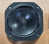
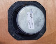
3. Any woofer suggestions (available from soundimports.nl or TLHP)?

4. would any other enclosure style be better for this application?

Any sort of comments, hints and ideas are welcome. I would be more than happy if I would get the level of bass I got from the 2x12 without the 212 Hz peak in the form factor I described.

New home, new system

Hello,

I plan to upgrade my current speakers (proac d18) with diy, my room is quite bad and speakers will be (very) close to front walls and will be quite close to side walls too.

I see diy as a way to get a better a speaker as a better price, I dont plan to tweak et get measurements, hence I need an available kit.

I plan to use some kind of totl driver (scan speak illmunator/revelator, seas nextel, purifi ...) with a fabric dome tweeter.

I was planning to build a small 3W, but considering the room and the simplicity of a 2W, I wonder if it is not a better solution right now. I could always build something bigger if I ever move in a bigger/better room.

Troels is an option and as a 3w exemple I considered Ekta mkii/SBA 7md and Purifi Fa/Illuminator 71 as 2W.

What do you think makes more sense 2w or 3w ? Any option/kit I should consider ?

Thanks for your help.

PS : Sound describing is always tricky but I am leaning more on the warm/non fatiguing side than cold/analytical

Foam gasket removal on Peerless TC9 fullrange

I'm getting a little flustered with removing the thin front foam gasket on my Peerless TC9 fullrange drivers. They don't want to peel off cleanly and the residue is hard to remove from the front flange, plus some of the gaskets are attached unevenly. Many of the gaskets are stuck to the thin fragile surrounds, so using chemicals is likely out of the question to avoid damage ie. isopropyl alcohol is definitely not an option as it harms rubber. These drivers are clearly made for rear mounting based on the presence of a gasket. It looks ugly when front mounting them.

Does anyone have an effective method for removing these things without harming the rubber surrounds? The first one took me almost 20 minutes to completely get off. There are over 50 drivers to do and I'm going to grow a beard faster than I can get the job done. Any good suggestions?
  • Like
Reactions: vassilis1984

Hello from Toronto

Hello Everyone!

I live just east of Toronto, Canada and spent most of my career in IT architecture and infrastructure engineering. I have been tinkering with electronics since I was a little and learned early with my Dad's Heatkit’s that building stuff is fun! looking forward to picking up some new ideas and skills for DIY projects!

I'll confess now: I am tubehead and enjoy warm sounds they produce but can't listen to tubes without other electronics you build yourself!
  • Like
Reactions: kodabmx

solder pin things

I'm struggling to find the correct name of the pins and or blades/crimps I sometimes see soldered into circuit boards. Sometime people wrap and solder wire around the pin. Some use the male crimp connectors soldered to the board and make connection wit the female crimp. Its the parts that go through the birds I can find.

Can anyone point me in the right direction?

Diatone P-610MB

I picked up a pair of these venerable full=rangers, mint condition and still in their boxes, off Ebay and am trying to decide what to do with them. AFAIK these have usually been used in vented cabinets, but when I tested the T/S parameters using DATS V3 these are the results I got:

Fs: 79.5 Hz
Qts:: 1.095
Vas: 20.94 L

To my limited knowledge, for a bass reflex enclosure the Qts is ideally below 0.5, and a value of 1.1. would make it out of the question.

Am I right about that? If so, does anyone have thoughts on what these would work with?


20220827_073850.jpg
20220827_073958 (1).jpg

a pair of MW for 2way?

Which pair's of MW will you use on a 2 way system in addition to a 10'' subwoofer system?
i'd figure out the SB29RDNC can reach average 94 db with almost flat from 2000 to 20k... i guess wil be my favourite at moment for my system

for the woofer/sub i will use KEF 10' PSW2010 driver from my old sub cabinet, i will reuse its amp to make active itself powered driver with new cabinet included in tower setup. (will use it in reflex box with FB40hz)
for the midbass section I'm undecided on what to use, most likely I will opt for a 30-litre sealed box with double drivers system.
my possible drivers are:

1. SB16PFCR20
2. RS-180P Dayton audio
3. Ciare HWB160
4. Hertz (for caraudio) MP165.3
5. Tang Band W6-623I
6. Ciare HW172
7. Scan Speak 18W/8424G00

any advice?
Thanks

Curt Campbell lifetime audio achievement award recipient!

There hasn’t been much posted about this, so I thought many of you would be interested. Curt Campbell received a lifetime achievement award for his contributions to DIY audio and his help and mentoring of new DIY speaker builders. Meniscus Audio presented this well-deserved award.

Personally, Curt has been a co-conspirator to numerous projects I’ve been a part of. Curt over the last 15 years has been my mentor, who I like to call, the genius who makes all of our projects sound as good as they do in our collaborations. As most of you know, Curt has many designs in addition to the ones I’ve been fortunate to be a part of. Many are available on his website and in kit form at Meniscus.

Congratulations Curt!

Attachments

  • Curt-certificate award (Large).jpg
    Curt-certificate award (Large).jpg
    164.8 KB · Views: 473
  • Like
Reactions: adason and helitim

ES9038PRO PCM or DSD autodetect

Hello, I have a build diyinhk dac board.
pcm to dsd autoswitch function is work ok without i2c controller?
In pcm it's sound great but in dsd is mono not stereo :-(

As source I used amanero:
if I connect I2S DATA/DSD1 (pin 3) and I2S CLK/DSD CLK (pin 4) sound comes from two speakers but mono.
if I connect I2S FSCLK/DSD2 (pin 5) and I2S CLK/DSD CLK (pin 4) sound comes from right speaker only.
if I connect I2S FSCLK/DSD2 (pin 5), I2S CLK/DSD CLK (pin 4) and I2S DATA/DSD1 (pin 3) sound comes from two speaker again mono.

I try two amanero's but they are chinese fakes.

Chip seller say that it's directly from factory.

Maybe problem is in amanero?

Toroidal transformer VA ratings and wiring help

The following amplifier power ratings are as follows:
  • 2 x 330 W at 8 ohms
  • 2 x 450 W at 4 ohms
  • 1 x 900 W at 8 ohms bridged
The toroidal transformer ratings are as follows:
  • I/P:
  • 0 -120 V at 60 hz
  • O/P:
  • 34 V - 0 - 34 V - 4.5 A
  • 34 V - 0 - 34 V - 4.5 A
  • 25 V - 0 - 25 V - 0.5 A
The power supply board has 4 capacitors rated for 63 V / 10000 uF

Do I understand correctly that the toroidal transformer has 3 dual secondary windings, 2 of which are rated for 34 V at 4.5 A, wired in series center tapped to provide 2 x 68 VCT AC to the supply board?

What is the VA rating of the given toroidal transformer?

Thank you kindly!

Attachments

  • Screenshot_20221113_182502.jpg
    Screenshot_20221113_182502.jpg
    270.2 KB · Views: 266

FS: Dynavector PE-1 Phono Enhancer

FS: Dynavector PE-1 Phono Enhancer (MC/MM preamplifier)

High/low level MC, MM and MI settings. Patented current input circuit. The PE-1 comes with matching AC power unit. Cable length: mains AC input 40cm, AC output to PE-1 box 135cm.

More info:

Dynavector DV PE-1 Phono Enhancer Manual | Vinyl Engine

Item located in the EU (Hungary). Price: 430 EUR, 500 USD (plus postage). EU buyer preferred due to customs difficulties outside EU.

Attachments

  • 20200927_142209.jpg
    20200927_142209.jpg
    588 KB · Views: 416
  • 20200927_142222.jpg
    20200927_142222.jpg
    557.7 KB · Views: 422
  • 20200927_142240.jpg
    20200927_142240.jpg
    390.8 KB · Views: 396
  • 20200927_143036.jpg
    20200927_143036.jpg
    489.6 KB · Views: 387
  • 20200927_143104.jpg
    20200927_143104.jpg
    550.7 KB · Views: 373
  • 20200927_143204.jpg
    20200927_143204.jpg
    523.3 KB · Views: 258

For Sale First Watt F3 DIY Clone Chas Sample boards and some parts

SOLD

Asking $85 including US shipping


For sale are a set of F3 clone boards, and some parts for a build.

From the Chas Sample group buy

https://www.diyaudio.com/community/threads/f3-clone-board-set-group-buy.373750/

Includes:

(2) Signal boards
(2) Output capacitor boards
(1) F1/F1J Clone PS Board
(30) Nichicon Fine Gold 1000uf / 35V audio capacitors for the output cap boards
(2) 10 ohm, 5W WW linear pots for tuning operating points
(2) pairs of LU1014 jfets, each pair matched and comes with the mounting daughter boards, grid resistors and connectors for flying leads. You need one pair and will have one pair in reserve

IMG_1496.JPGIMG_1497.JPGIMG_1498.JPGIMG_1499.JPGIMG_1500.JPGIMG_1501.JPGIMG_1502.JPGIMG_1503.JPG

Nakamichi PA7II- are 2SA1837 and 2SC4793 suitable replacements for 2sc3298 and 2sa1306 in this amp?

2sc3298 and 2sa1306 in one side are getting too hot and bias and dc offset will not adjust properly. These are the beginning stages of amp and not the outputs but are heatsinked. I see where alot of people use 2SA1837 and 2SC4793 as direct replacements in many amps but what concearns me is the collector current is 1.5 in originals and only 1 amp in replacements. This amp is too valuable to gamble with if it could cause damage. Has anyone replaced these in this amp with success? Is the collector current OK to be lower in this case? I cant find genuine replacement for originals only chinese stuff on ebay which I dont trust. Thanks

Sumiko S.5 just died, I'm sad

My little Sumiko S.5 subwoofer died last week. Stopped working. Powering up will give a small plop sound (normal). The auto on function still works, because when I send a signal (both high level and also line level) the unit switches on. It just won't produce the pleasant bass sounds anymore.

Sadly it is just out of the warranty period, so I opened the unit to have a little look myself.

I'm not able to repair it myself (don't have the equipment and don't trust my hands with expensive stuff I bought 😡). Besides that, I can't find schematics or repair manual on the net, so a quick question here.
I seems to me that a capacitor has gone bad and did some damage. I have no clue if that is the case, but it looks bad to me.

Would a repair in a repair centre be expensive these days? I could bring it, but if the repair will be over € 200,- / US$ 200,-, I think I will go for a new, a little bigger subwoofer.

Appreciate your replies.
Thanks,
Peter

Attachments

  • 20230115_175447.jpg
    20230115_175447.jpg
    477.9 KB · Views: 345
  • 20230115_174944.jpg
    20230115_174944.jpg
    570.3 KB · Views: 312
  • 20230115_175029.jpg
    20230115_175029.jpg
    318.7 KB · Views: 316

Orchard Audio to Exhibit at the 2023 Florida International Audio Expo

I am proud to announce that the company will exhibit at the Florida International Audio Expo (FAE), on February 17-19, 2023, in Tampa, Florida.

Orchard Audio’s exhibit will feature the following award-winning products:
Starkrimson® Stereo Ultra: 500W gallium nitride (GaN) stereo audio power amplifier
Starkrimson® Mono: 150W GaN monoblock audio power amplifier
PecanPi® Streamer: Networked audio player (transport) with built-in DAC and headphone amplifier

Starkrimson amps are fully analog, state-of-the-art GaN audio power amplifiers developed to provide the listener with a truly life-like musical experience, presented with every significant detail intact. GaN technology benefits include less harshness, cleaner highs, better transparency, and higher detail. In addition to using GaN transistors, Starkrimson amps use Orchard Audio’s proprietary dual feedback modulator, keeping the amplifier fully balanced from input to output.

Both amplifiers will use the company’s PecanPi Streamer as the source. The PecanPi Streamer is an ultra-high-performance networked music player that combines a streamer, DAC, and headphone amplifier into a single device. The PecanPi DAC brings studio-quality sound to your home. It can be connected to any existing stereo amplifier, preamplifier, or receiver, as well as headphones.

Orchard Audio will exhibit in room 506.

Speakers will be supplied by Soundfield Audio (https://www.soundfieldaudio.net).
Cables will be provided by Triode Wire Labs (https://www.triodewirelabs.com/).

For FAE event information, visit https://floridaaudioexpo.com.

About Orchard Audio, LLC
At Orchard Audio, we believe that listening should be an experience. With a range of expertly designed, high-performance DACs, streamers, and amplifiers, we’re helping you elevate the sound in your home theater, listening room, or recording studio. As passionate music lovers, we know how important your music is to you -- that’s why each of our products is handcrafted in the U.S. with you in mind.
www.orchardaudio.com
www.twitter.com/orchardaudio
www.facebook.com/orchardaudio
www.instagram.com/orchardaudio
www.linkedin.com/company/orchard-audio-llc

plans for a super minimalist mono tube preamplifier with onboard power supply

New/old prospective DIYer Looking for plans/info/article on constructing a minimalist Mono preamp with PS for a single Dynaco Mk III (2 x 6550s, 5AR4, 6AN8 ) amplifier.

Ideally using 1 or 2 12Ax/u/t tubes and/or EF-86, and a 6X4 rectifier (I have a bunch of those).Phono preamp for magnetic cart, input for CD player, Volume pot. No tone or balance controls.

Not sure if this is adequate info, so please excuse my total lack of knowledge in this realm.. but I can solder! lol
Never built anything except a Heathkit kit amp a very long time ago, like to get back into it, with a simple project. Thanks!
Roger in NY

Stumped on Simple P-P Build

Hello all!

I have previously built a Simple SE, and a TSE-II. Have had the parts to build a Simple P-P for years and finally got around to building it.
After firing it up for the first time and checking the voltages, I ran into a bit of a strange problem:

  • The issue happens on both channels equally (so whatever I did wrong, I did it consistently wrong at least!)
  • Music going in at roughly .75 Vrms
  • Music coming out the 8 ohm tap at 10mV (perfectly clear, sounds good, just super super quiet!)
  • Checked all of the components with a meter to the parts list / schematic.
  • Power supply portion seems good: B+ 330v, 5v = 5v, Heaters = 6.9v.
  • Thinking it may be in the first stage of amplification = g1 of the EL84 is only getting .25v to ground. After coupling caps, almost no voltage differential between R111 & R115
  • Tried it with and without feedback. In both UL and Pentode wiring.
  • Running JJ ECC81 and EL84 tubes.

I'm sure that I did something stupid, but just can't seem to figure out what. Any help would be much appreciated!

-- Pete

Attachments

  • IMG_9262.jpeg
    IMG_9262.jpeg
    204.3 KB · Views: 144
  • IMG_9263.jpeg
    IMG_9263.jpeg
    348.2 KB · Views: 131

Loud Thump even after delay

Hi everyone,

I built a LM1875 guitar amp and it works great except for the thump when the relay kicks in.

Ive used a 555 to delay the turn on and ive even got it out to 8 seconds as a test and it still happens. The 2 HPF / LPF switches also have small pops when they are changed.

I assume since the output cap has ample time to charge up i have either a very leaky capacitor or another source of DC getting to the output. Is there anything blatantly obvious that you guys can see here that could be the cause? I'm going to redesign my PCB so any notes would be great.

PS, That reversed cap at C9 is installed the other way, despite the schematic 🙂
Amp.png

QUAD 303 voltage change

Can anyone help.
I have an early Quad 303 and am planning to send to a friend in USA with 120volt mains voltage . The voltage selector has only 3 settings 200,215 -216,232 -233,250 I am aware of the main fuse change when used with 120 volts however am at a loss on how to change. The later model selectors do have a 120v setting so setting is user friendly
Would appreciate any help instructions..

I think I have found a good candidate for a woofer-mid to "Run Wild"

I think I have found a good candidate for a woofer-mid to "Run Wild" in a ported 2-way.

It was a long search, and wow, some modern drivers have out-of-intended-bandwidth humps that make the one on the Eton 5-312 look like an anthill. Here's the Kartesian 6.5-inch.

Kartesian 65.png

And here's Purifi's new 5.25-inch woofer-mid:

Purifi 525.png

The Purifi appears very well-behaved at the top of its range. The scale is different, but still...

So, I will investigate further.

One of my "Golden Ears" friends, who is both an LP collector and a loudspeaker collector, came over and he was very very happy with the sound of the Eton 5-312 Running Wild.

ciao,

john
Projects by fanatics, for fanatics
Get answers and advice for everyone wanting to learn the art of audio.
Join the Community
507,564
Members
7,877,160
Messages

Filter

Forum Statistics

Threads
405,730
Messages
7,877,160
Members
507,564
Latest member
Smelting7793