WOTS WHA-53
This is a very high-quality power amplifier with no feedback loop.
Where to post this project? Tube forum? Solid state forum? 8 triodes beat 4 MOSFETs. So, perhaps this is the best place, even considering the high voltage.
This project uses tubes in the Front-End, so the supply voltage is necessarily high and dangerous to health, if not fatal. Approximately 350V is present at the highest voltage point.
You are warned if you decide to tackle this project the responsibility is all yours, nothing can be attributed to the writer, who declines any responsibility.
This project was born from the solicitation of my friend Stefano di Rottofreno (Italy) who had browsed the Audiodesignguide.com site (Andrea Ciuffoli), and liked a lot the "Amplifier End 2022", an exciting project, with valve Front-End and solid-state Back-End, in “Circlotron” configuration.
The points of interest of this project are:
polarization of the final stage in Class A;
“Circlotron” circuitry, which guarantees maximum symmetry;
a single pair of final transistors;
60W/8Ohm output power, sufficient for normal use at home with medium efficiency loudspeakers.
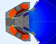
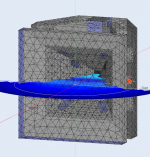
The critical point is in the Front-End, which uses a single-ended interstage transformer, which necessarily has the gap to avoid core saturation. The gap picks up and radiates, and this leads to a certain difficulty in realizing the layout because the generation of unwanted noise must be avoided. Furthermore, the recommended transformer is very expensive.
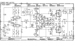
Once it was decided to adopt the Back-End as per the original project, it was a matter of deciding how to make the Front-End (gain stage and phase shifter), consequently making only the necessary modifications to the Back-End, for the part regarding the bias.
We have considered different solutions, focusing on a mu-follower differential, followed by a cathode follower to interface the “Circlotron” Back-End.
At this point, Stefano was no longer able to follow the project, but I wanted to go ahead anyway, and I started looking for the "best practice" in terms of phase shifters. I discovered that the "Cathodyne", if well configured and well used, is at the top of the list because it is maximally symmetrical; but it has two problems:
difference of the output impedances on the opposite phases;
the phase shifter triode filament must be polarized at a high voltage with respect to mass and, in order not to exceed the maximum Vkf values of the other triodes, it is always polarized negatively with respect to its cathode, while the correct configuration requires the filament to be slightly positive with respect to the cathode.
The first problem is solved very easily by presenting a double cathode follower on the outputs of the phase shifter triode made with a very easy-to-drive double triode.
The second problem seems to be negligible, as no author cares much about this aspect, so I feel entitled to neglect it too, even though this is the first time I present a project with a reverse polarized filament.
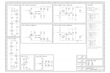
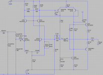
There are several examples of “Cathodyne” on the net, I chose the Williamson input stage, formed by a first amplifier triode coupled directly to the phase shifter grid. This solution, with the values shown in the scheme (ref.
www.valvewizard.co.uk/cathodyne.pdf – by Merlin Blencowe) ensures a greater gain than the differential.
In addition, "Cathodyne" has a very intriguing feature, which takes me back in time, when, still a child, I enjoyed making the transistors oscillate, in order to have a transmitter and hear my voice on the home radio. Transistors were made to oscillate by introducing positive feedback created by a capacitor placed between the collector and the emitter. Transposing the concept to the "Cathodyne", a small positive reaction can be dosed very carefully to increase the gain, if necessary, by placing a resistor between the anode and the cathode. I remember that Hiraga posted somewhere a solution in this sense, but I don’t remember any explanation. Reasonably, the operation coincides with what I said. However, here the gain of the Front-End is high enough and doesn’t require any increase.
Furthermore, I am against the use of CCS in the presence or proximity of the audio signal. I only use the CCS, (relying on my memory) in the "Virtual Battery" power supply and in the "Diamond Buffer". So "Cathodyne" is the solution I prefer because it has none.
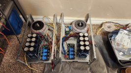
Having established the definitive configuration, taking the dual mono construction for granted, it was a question of identifying a solution to house the physical/functional blocks.
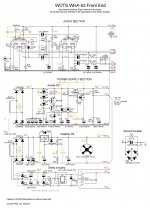
For the Front End:
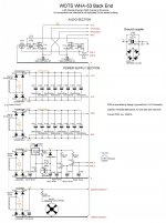
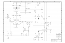
For the Back End:
final stage;
power supply “A”;
power supply “B”;
leveling and reservoir capacitors “A”;
leveling and reservoir capacitors “B”;
bias power supply;
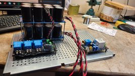
loudspeaker protection power supply;
soft start;
speaker protection;
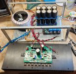
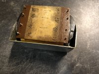
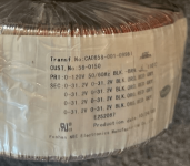
300VA transformer (being the same surface area, I chose an exaggerated 600VA);
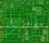
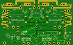
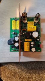
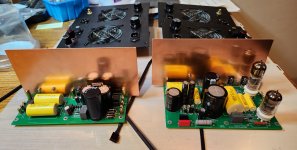
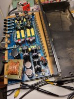
I managed the PCB's design to contain all the elements of the Front-End on a single board, while the transformer and the soft-start remain outside. Even all the elements of the Back-End are on a single board, while the transformer, the speaker protection, and the soft start remain outside.
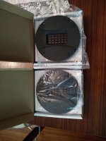
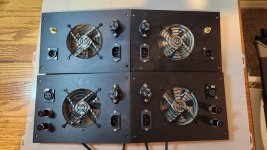
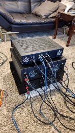
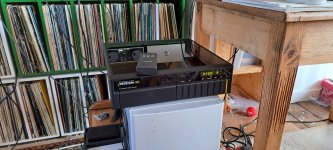
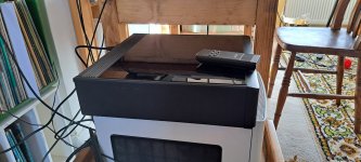
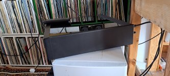
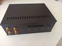
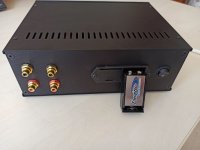
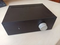
HiFi2000 has in his catalog the Monoblocks, very suitable cabinets for a dual-mono realization. But, in this case, they are small, and it is not possible to fit a complete channel in a single Monoblock. So I chose the dual-mono / dual-body configuration, housing the Front-End in two Monoblocks without a heatsink, and the Back-End in two Monoblocks with a side heatsink. Four cabinets in total.
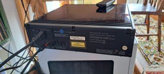
If the circuitry is a simple one, the mechanical part is a laborious one, the worst moment lies in the realization of the four rectangular holes to house the IEC-C14 sockets.
Calibration.
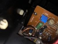
There are only two calibration points, that concern the absorption of the "Back'End", here is what to do:
turn on only the power supply relative to the bias and adjust the two trimmers to read 200mV on the 47KOhm resistor connected to the central pin of each trimmer;
turn off and discharge the bias power supply;
interpose a 0.1Ohm resistor between the Drains and their positive side of the high current power supply;
turn on the whole "Back-End" and adjust the trimmers to read 100mV across the 0.1Ohm resistors using two multimeters;
once the correct absorption value and symmetry have been obtained, move one of the two multimeters to the loudspeaker output and bring the offset to zero by adjusting the trimmers.
At the time of writing, I'm listening to background music from Enrique Chìa's collection, waiting for the WHA-53 to run in its components. But already now, after more than 5 hours of operation, I can say that it has exceptional coherence, which is the aspect that most distinguishes it from the valid WHA-217, which it replaced. To find a similar sound I have to go back to 2013 when I listened to an OTL 4 x 6C33C power amp in the SiAudio listening room in Naples. An experience that for me has been, ever since, my term of comparison. Finally, here we are! This WHA-53 probably outclasses the OTL power amp. Or probably not, but the two are very close.
Thanks to:
Andrea Ciuffoli for publishing the "Amplifier End 2022" whose Back-End is used here;
Merlin Blencowe for publishing the HiFi "Cathodyne" scheme;
my friend Stefano, who brought Ciuffoli’s "Amplifier End 2022" to my attention;
HiFi200 for their very high-quality cabinets, now even better than in the past;
JLCPCB for their excellent service.
Gerber files for PCB making are available for free to those interested.