This article focuses on audio system design for the DIY enthusiast implementing a stereo system for home use. There is a lot of information available for designing audio circuits, but precious little on interconnecting those circuits into a total audio system to achieve maximum performance. Interconnecting circuits to create an audio system involves connecting signals and grounds , both within a single component as well as between components. This article has the most benefit for the person constructing his or her own equipment, rather than merely interconnecting finished components. Although much of the information presented is applicable for professional installations, those installations face a myriad of problems due to physical size, number of components and different types of components, which are not addressed here.
Although I use electron tube circuits for many examples in this article, the concepts presented are valid for solid state circuits as well. Most, if not all digital circuits will use integrated circuits and I cover interconnecting digital electronics with analog electronics.
Chapter 1 - Ground
The term “ground” is problematic because it can mean so many different things. Often a designer will lump all of the meanings together and in an indiscriminating manner, connect everything that needs to be “grounded” together. Lumping all of the meanings together and treating them all the same causes problems that wouldn’t happen if the different uses of ground were kept separate and each treated in a manner appropriate for its use. Therefore a good place to start would be to tease all of the meanings apart so we can address them separately.
The first ground we encountered was playing in the dirt as a child: we call the place where the grass and trees grow ground. However, considering the electronics in an airplane or a cell phone, this ground is not necessary for electronic circuits to function – its only interest in electronics is as a sink for lightning strikes. I’ll refer to this ground as “earth.”
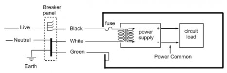
Recognizing that high voltage is lethal, the various standards organizations around the globe have instituted safety standards for mains-attached electrical equipment. The first assumption in these standards is that a human body in the vicinity is at earth potential. Therefore the standards require that a metal chassis and any exposed metal parts be at earth potential by specifying a wire be connected between the chassis and a connection to earth at the circuit breaker panel. This ensures that any electrical fault within the equipment will not be a hazard to anyone that comes in contact with the chassis. A second benefit of this earth connection is that it provides a low-impedance path to earth for a lightning strike. This minimizes potential circuit component damage as well as providing protection from electrocution. A third facet of the standards is the means by which a fuse will be blown or a circuit breaker tripped in the event of a fault where the mains voltage is connected to the chassis. As shown in figure 1-1, in the event of a fault, a large current will flow from the circuit breaker panel, through the electrical wiring to the equipment, through the fault to the chassis, and then through the safety wire back to the circuit breaker panel. If there is an appropriately-sized fuse in the equipment, it will blow; otherwise the circuit breaker will trip. It is a good idea to provide an appropriately-sized fuse in the equipment because it will blow a lot sooner than the circuit breaker, thereby quickly eliminating the large current which may damage expensive components. Note that the connection to earth at the circuit breaker panel does not come into play for a fuse to blow or breaker to trip. Also, no current flows in the safety wire when there is no fault present. I’ll refer to this ground as “safety ground.”
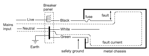
Figure 1-1, Safety ground: showing the current from a fault between the power line and the chassis.
Adhering to the safety standards by providing a safety ground provides some protection for equipment manufacturers from expensive liability law suits. While you may not be worried about law suits – you are liable for any damage, injury or death caused by the equipment that you build – you should be very concerned about your personal health and well being as well as that of your loved ones. Equipment lacking a safety ground has caused fires, injury and death.
Do not under any circumstance, for any reason, disconnect or disable an existing safety ground, or fail to include a safety ground in any equipment that you build. But, you say, “what about my CD player, it has a two-wire power cord without a safety ground?” Consumer component manufactures have engineers with the skills to design a double-insulated product which is inherently safe without a safety ground. This is not a trivial task and should not be attempted by amateurs that do not have the necessary skills. Double insulated products are designed such that any single fault cannot cause power line voltage to be present on any exposed part, including the chassis. Special provisions must be made to preclude a winding-to-winding fault within the power transformer.
The good news is that, in a properly designed audio system, a safety ground will not hurt and may actually help produce optimal sound quality. We’ll see how this works a little later.
Most audio components will have one or more power supplies. I think of the purpose of a power supply is to provide the operating environment for the audio circuitry. That is to say, it provides the necessary voltages and currents to establish an idle state separate from any function that the circuit is intended to produce. For example, in a triode vacuum tube amplifier, the power supply supplies plate current, plate voltage and a bias voltage. It will also supply screen grid voltage for a pentode amplifier. Current will flow from the positive terminal of the supply, through the load and back into the negative terminal of the supply. For convenience in making voltage measurements, understanding and using the power supply, a designer will usually designate some point in the power supply as “ground.” This is usually the negative terminal of a positive supply, or the positive terminal of a negative supply. I will refer to this ground as “power common.”
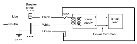
Figure 1-2, Power Common: In this example the negative terminal of the power supply is chosen to be power common.
What would happen if some node with voltage from the power supply were to become shorted to the chassis? The chassis is at earth potential (through the safety ground) so the shorted node would be at earth potential – so far, so good. We would like to detect the fault and cause the fuse to blow, which requires a complete path for the fault current to flow from the power supply, through the fault to the chassis and back to the power supply. Although it doesn’t have to be, to avoid confusion most designers choose power common as the point to connect to the chassis for the return path. Note that under normal, non-fault, conditions, no current will flow in the connection between power common and the chassis. The only purpose for this connection is to direct fault current.
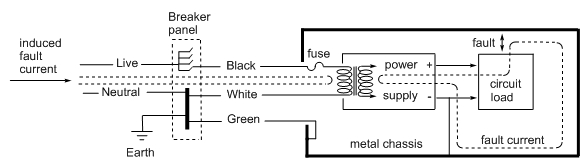
Figure 1-3, Power Common and a fault
Figure1- 3 shows that a fault causes a large current to flow in the secondary of the power transformer, which in turn induces a large current in the primary of the transformer. Note that no current flows in the safety ground for this fault.
Power common should also be used as the “ground” reference for any vacuum tube filaments. This may be by a direct connection or by a bias voltage.
It goes without saying, that in order for an audio component to be worthwhile, it must process an audio signal in some manner. For a signal voltage to be meaningful, it must be referenced to something. In some cases, as in a differential amplifier, the signal is presented to the positive input and the reference is the negative input. In other cases, as in a single-ended amplifier, the signal is presented to the input and the reference is “ground.” I will call this ground “signal reference.” A triode is a three-terminal device: the input signal is presented to the grid with the cathode as the reference, and the output is taken from the plate with the cathode as the reference. The cathode is usually connected to power common, either directly or through a bias resistor. Thus, signal reference is connected to power common; however no current flows in the connection between power common and the signal reference. Each circuit has a signal reference and some circuits may be analog while other circuits are digital. It is a good idea to keep the digital references separated from the analog references.
The last use of the term “ground” that I will address is shields. There are basically two different shields in an audio system – chassis and cable shields. There are two important characteristics of a shield: the continuity of the enclosure and the material it is made of. By continuity, I mean that for a shield to be maximally effective there must be no holes or gaps in the chassis or in the connection between the cable shield and chassis. This may not be practical in an audio system, but it is good to keep in mind as a goal. Of course, plastic or wood will offer no shielding, while copper or aluminum will provide electrostatic shielding and steel or mu metal will provide both electrostatic and magnetic shielding.
Rule 1. In Morrison [1] (page 39) states, “An electrostatic shield enclosure, to be effective, should be connected to the zero-signal reference potential of any circuitry contained within the shield.”
It is Important to not have a chassis isolated – it must have some ground. Everything has a potential to everything else. Either control it or you have noise potential. Thus a chassis or cable shield must be connected to signal reference; however, no current flows in the connection between the shield and the signal reference.
I use the terms “ground buss” and “star ground” in this article. A ground buss is a piece of wire at ground potential. A star ground is two or more grounds connected to one physical point. A star of stars is just that – several star grounds in turn all connected to a single point.
So in an audio system we have earth and possibly multiple safety grounds, power commons, signal references and shields; all interconnected. I have said that under normal, non-fault, conditions that no current will flow in these interconnections. This is not entirely true for there is noise in the system which may flow between the different “grounds” and cause degradation of the sonic performance of the audio system. Therefore the goal is to minimize the noise traffic in a system by first reducing the noise and second, by reducing the propensity for the remaining noise to move around; or alternatively to control the paths so as to minimize the effect. Let’s start by taking a look at noise.
Chapter 2 - Noise
All electrical noise, with the exception of lightning induced noise, is produced by man-made electrical or electronic devices, including all of those in your home. Of course we can’t exclude the audio system itself from producing noise; each component affecting itself as well as all of the others in the system. The noise is either radiated through space or conducted through wiring into the audio system as well as between the components in the system.
We think of the mains power as a solid 120V, 60 HZ (or 230V, 50 HZ) but in reality it isn’t very clean. It harbors noise from DC, to harmonics of the power line frequency, to spurious junk into the megahertz range. All of this noise can get into the audio circuitry and produce readily identifiable noise in the form of hums and buzzes, or aberrations in the sound, which while not something you can put your finger on, messes up the sound.
The noise is running on a two-way street with power line noise projected into the power supply and power supply noise projected into the power line. Additionally, noise from both sources is projected into the chassis, and thus the system of grounds. This is discussed in detail by Eric Juaneda
here and by Bill Whitlock in Jensen
AN-004.
Power line noise comes in two flavors, differential noise and common mode noise. With differential noise, the noise voltage is impressed between the two power lines – hot and neutral. With common mode noise, there is no noise voltage difference between the two power lines; rather, the noise voltage is impressed between safety ground and the two power lines.
So, what can we do to ameliorate the noise from the power line?
- Clean up the power line. Any electrical device in your home that contains a switching power supply is dumping tons of electrical garbage into the power and safety ground wires. Of particular interest are TVs and DVD players that are interconnected with your audio system or plugged into the same AC power branch circuit. In an AudioAsylum post here, Charles Hansen identifies the problem and recommends disconnecting and un-plugging all such components. Merely turning them off doesn’t cut it – even though you think that they are off, their power supplies are still on and are injecting noise into the power system. The problem is not limited to TVs and DVD players; rather, devices such as computers and microwaves anywhere in the home, and particularly in the same branch circuit as the audio system, are also culprits.
- Clean up the safety ground. Safety ground is really the flip side of the power line because the power is referenced to the ground. By cleaning up one, you can’t help but clean up the other. Even though safety ground is connected to earth, it is a long wire that is routed around the house, picking up all sorts of electrical noise because it is an RFI antenna. Some folks have suggested adding a second earth ground directly from the audio system, while others advise that an additional ground may actually cause more problems than it solves. A single, dedicated safety ground along with a dedicated power branch may be a good idea; however this is expensive because it must be installed by a licensed electrician. Much the same result can be achieved by dedicating one of your existing branches to your audio system. This branch should ideally have no other equipment connected to it, or at most, only what I call “benevolent loads” – for example, ordinary incandescent light bulbs without a dimmer control.A thorough explanation of a “Technical Ground” is contained in Jim Brown’s grounding article here.
Class 2 devices side-step the issue of a noisy safety ground because they, of course, do not have a safety ground. However, it is important to note that this solves the problem only as long as all powered devices in the audio system are Class 2 devices. That is, there can be no connection to earth anywhere in the audio system, or in any attached component, for example, a computer that is not galvanically isolated. The problem of interconnecting Class 2 devices (without a safety ground) with Class 1 devices (with a safety ground) is shown in figure 5 of the Juaneda article and discussed in detail in the Jensen AN-004.
- Eliminate DC on the power line. We normally think of noise as some sort of alternating current phenomena; however direct current on the primary of a power transformer is also noise. A thorough discussion of the problem and a solution is presented in Rod Elliott’s article.
- Choose the proper power line polarity on each component. Noise from the power line in the form of AC leakage current will be transferred to the core and frame of the power transformer through the parasitic capacitors as shown in the Juaneda article. Because of the way a power transformer is constructed, the parasitic capacitors are different values; and because the neutral power line is connected to the safety ground, the amount of noise on the two sides of the power line is different. These two factors work together to cause the amount of leakage current to be different depending on the polarity of the connection of the power to the transformer. The result is a voltage, with respect to earth, impressed on the chassis. It is most unlikely that this impressed voltage will be the same on two different chassis in the audio system and when those chassis are connected together, noise voltage will flow in the interconnection. This is discussed in Charles Hansen’s AudioAsylum post here and a way to test the polarity is shown here. Remember, the final polarity change should be done where the power line connects to the power transformer so as to keep the fuse and power switch on the hot side of the line. Note that this problem exists in class 2 devices (without a safety ground) as well as class 1 devices (with a safety ground.) This is discussed in detail in Jensen AN-004.
- Include a line filter on equipment that you build. The best kind to use is one that has the filter integrated into the power entry module, like that shown here. Unfortunately, a power line filter is a two-edged sword; although it does filter the noise, it dumps common mode noise into the safety ground (which we want to clean up.)
- Use a power conditioner. By its very nature a power conditioner isolates its attached components from the power line. The conditioner can be used two ways: First, for isolating sensitive audio components from the noisy power line, and second, for isolating noisy devices that contain switching power supplies from the power line. Of course, the audio components and noisy devices should not both be connected to the same power conditioner. Although the power conditioner does a good job of cleaning up the power line, the safety ground is passed directly through the power conditioner. Therefore, the suggestions for cleaning up the safety ground discussed above may still prove beneficial.
- Use a shielded power transformer. A shielded transformer has a shield that eliminates the parasitic capacitors between the primary and secondary windings, thus eliminating the AC leakage currents between those windings. It isn’t often that a shielded power transformer is needed but it is good to know that it is available for that rare case.
As well as minimizing the noise coming from the power line, it is important to minimize the noise that a component injects back into the power line. We will see why this is so later when we talk about interconnecting components.
Power Supply noise can be minimized by careful design of the power supply, paying attention to the choice of rectifiers, snubbers and filter networks. What can we do to minimize the noise injected back into the power line?
- Don’t include switching power supplies in any equipment that you build.
- Provide a more constant load. Because audio components are not resistive loads, the manner in which they draw current from the power line is not constant. This irregular load presented to the power line contributes to the noise on the power line. Some things you can do here are regulated supplies, class-A circuits, choke-input power supplies and Minimal Reactance Power Supplies.
- Use low-noise rectifiers. Different kinds of rectifiers used in a power supply convey different characteristics to the sound of an audio circuit. Some sound better for one circuit and worse in another circuit. Whichever one you choose to use for a particular circuit, low noise is an important criterion. Tube rectifiers, Schottky diodes and Fast Recovery Epitaxial Diodes (FRED) are good choices.
- Use a snubber on the rectifiers if needed.
- Include a line filter on equipment that you build. Since the noise is on a two-way street, the filter will help both ways.
- Shielded power transformer. Again, rarely needed but good to have available.
We have talked about electrical noise and what can be done to minimize the noise. All the electrical noise in the world doesn’t matter a bit unless it affects the signal. On the other hand, just a tiny bit of electrical noise can wreak havoc if it shows up in the wrong place. In order for the noise to affect the signal it must be routed in such a way as to interact with the signal. Careless mixing and interaction of grounds is the biggest cause of audible degradation of the music in an audio system, so let’s take a look at how this works.
To understand what can go wrong we need to understand something called Common Impedance Coupling. Simply stated, Common Impedance Coupling is the way that noise gets mixed in with a signal. Noise can get mixed with the signal in a couple of ways: first, “conductive coupling,” when two circuits share the same path, and second, “radiated coupling,” when noise from one circuit is radiated into another circuit carrying the signal. [12]
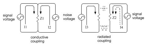
Figure 2-1, Two forms of Common Impedance Coupling.
The circuit on the left of figure 2-1 shows two current loops, one loop with the signal and a second noisy loop. Impedance Z1 is a sensitive spot in the circuit, perhaps a signal reference buss, which is common to both loops. The signal current, I1, and the noise current, I2, both pass through Z1 creating a voltage that is the product of the impedance and the sum of the two currents. The circuit on the right of figure 2-1 also shows two current loops, one with the signal and the other with noise. In this case the sensitive impedance, Z2, is not common to both circuits. However the two loops are situated such that there is capacitive or inductive coupling between them and the noise voltage is coupled into the signal loop. The resultant current is a composite of the signal current and the noise current which creates a voltage across Z2 that contains a mix of the signal and noise. There are two loops in each of these examples, but in reality the Common Impedance Coupling could be the result of several loops or a combination of conductive coupling and radiated coupling.
An example of a problem caused by radiated coupling is with the orientation of transformers in a vacuum tube amplifier. Depending on the orientation of the transformers with respect to each other, the output transformer may pick up the radiated field from the power transformer, causing an audible hum. Simply rotating one of the transformers may be sufficient to remedy the problem. Otherwise, increasing the distance between them will eliminate the problem.
Careless or poorly chosen routing of wiring can also cause problems with radiated coupling. It is important to keep filament wiring tightly twisted and laid close to the chassis. Low-level signal wiring should be kept as far as possible from power and filament wiring. It is a good idea to use a twisted pair for signal wiring, the signal wire twisted with its signal reference. When signal wiring must cross power or filament wiring, they should do so at right angles.
Chapter 3 - Interconnecting Components
There are two aspects to an audio connection: the signal and the ground. While both are equally important, designers have focused on the signal and left the grounding to chance. Thus poorly chosen grounding is the largest cause of audible hum and buzzes in an audio system. We will cover both aspects of an audio connection.
Audio components have either balanced or unbalanced interfaces. Those interfaces are similar in that they both have two wires – a signal and a reference. The difference is: on a balanced interface the impedance to ground is the same for the signal and reference; while on an unbalanced interface the impedance to ground for the signal is different than the impedance to ground for the reference. Usually the reference of an unbalanced interface is connected to ground and the interface is called “single-ended.” This term is unfortunate because it can obscure the fact that it is still a two-wire interface and lead designers to indiscriminately choose any convenient ground as a reference. Note that the kind of connecter used for the interface has nothing to do with if it is balanced or unbalanced; however most balanced interfaces use an XLR connector and most single-ended interfaces use an RCA connector. Why would you want to use one over the other? The ubiquitous single-ended interface is cheaper to build; while the balanced interface gives better noise performance. That being said, if you are using commercial components, it really comes down to what those components hand you.
Let’s start by looking at the ground aspect of interconnections.
3.1 - Balanced Interconnections: Grounding
The good news is, compared to a single-ended connection, it is relatively easy to get a balanced interconnection right; the bad news is, it is also easy to get it wrong. In fact many, if not most, of the balanced interfaces available on both commercial and professional audio equipment got it wrong. [12]
To see what could go wrong let’s take a side trip into power supplies. It goes without saying that the largest contributor of noise within an audio component is its power supply. I won’t go into power supply design here but I will cover one important area – ripple noise on an internal power supply ground buss. Figure 3.1-1 shows a schematic diagram of a simple power supply with an internal ground buss. Ripple current flows through this buss from the filter capacitors to the center tap of the power transformer. There is more ripple current in the capacitor closest to the transformer, with progressively less as the filter progresses. Even though the buss may be a short wire or printed circuit trace, it has finite resistance so a noise voltage is developed by the ripple current flowing through the buss. If signal reference current is routed through the power supply buss, this noise voltage will be impressed onto the signal by Common Impedance Coupling.
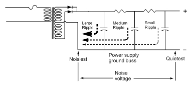
Figure 3.1-1, A typical power supply.
Now let’s see what happens when we combine this power supply with a poorly chosen grounding system, which is employed in many components. Figure 3.1-2 shows an example of a piece of equipment that has a severe ground loop problem. Knowing that the center tap of the power transformer is the noisiest point in the device, the circuit designer connects this point to the chassis at the same point that the safety ground connects to the chassis. He thinks that somehow this will drain all of the noise to earth. Unfortunately, the earth is not a huge electron vacuum cleaner – in order for current to flow anywhere, there must be a return path and a voltage difference between the input and return of the loop. Of course the power supply must be connected to the audio circuit so the designer dutifully connects the quietest point on the power supply ground buss to the audio circuit ground. Come time to connect the input XLR connector to the circuit, the signal on pin 2 and the reference on pin 3 is connected to the + and – inputs of the differential amplifier. What to do with pin 1 on the connector? Well, pin 1 is the shield and the shield should be grounded, and the shield is on the same cable with the signal, so why not connect pin 1 to ground of the circuit where pins 2 and 3 are connected? Okay, done. The designer should have been thinking outside of the box (his own box) when he designed this grounding arraignment. If he had, he would have seen that he had created a ground loop with the attached component. The attached component connects the safety ground to the cable shield, either directly by the chassis (as it should be), or worse, indirectly through a lame grounding arrangement like the one in the first device. The loop contains the power supply ground buss and the signal reference. The noise current on the ground buss together with the finite resistance of the buss, provides a voltage across the buss which will drive noise current through the loop. The noise current through the loop together with the finite resistance of the signal reference will develop a noise voltage in the signal reference. Now that the signal reference is dirty there is no hope in achieving a clean signal.

Figure 3.1-2, The Pin 1 Problem.
Neil Muncy identified this problem and dubbed it the “Pin 1 Problem” in his AESJ article [12] because pin 1 of the XLR connector was connected to the wrong place. The shield and pin 1 should have been connected to the chassis as shown in figure 3.1-3 rather than the signal reference.
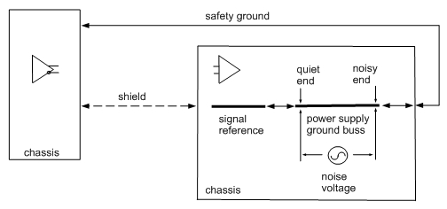
Figure 3.1-3, The Pin 1 Problem Fix.
By connecting the shield to the chassis rather than the signal reference, there is no longer a loop for noise current to flow in - thus the signal reference is clean. The internal ground structure is still not right and I’ll address that when I cover unbalanced interconnections.
It is important for the shield to be connected to the chassis at both ends for several reasons: improved shielding, improved headroom and maximum CMRR as is discussed
here. Galvanic isolation provides the possibility of eliminating a Pin 1 Problem, it does not guarantee it. Notice that the cable shield provides a second path (with the safety ground) between the grounds in the two chassis. If either component has poorly chosen grounding, a Pin 1 Problem will surface. There is controversy in the pro-audio community whether the shield of a balanced connection should be connected at both ends or only at the driver end. There are pros and cons to each with the biggest factor being the complexity of interconnecting a large professional system. This, together with the large number of devices suffering from a Pin 1 Problem has led many installers to favor the driver-end-only solution. The technical aspects of the question are discussed in a side bar in Bill Whitlock’s
article on audio interfaces. A home stereo system is a lot simpler than a pro instillation and the cables are a lot shorter thereby greatly reducing the common mode noise problem. Assuming that you can eliminate any Pin 1 Problems, the advantages of connecting the shield at both ends win out in a home stereo system. However, if you cannot eliminate a Pin 1 Problem in an attached component, the driver-end-only is an easy solution. Note that off-the-shelf cables have the shield connected to pin 1 at both ends, so you will need to modify the cable to implement the driver-end-only connection. I prefer modifying the cable rather than the wiring of a component because at some later date you may want to attach a different component and don’t want to have to remember to re-wire the interface. It is a lot easier to keep a pair of driver-end-only cables in your stash of cables – but remember to label them as such.
Before I go into single-ended interconnections I want to clarify one thing about safety ground in the figures. The figures show safety ground directly connecting the two chassis. Of course this is not accurate; rather both chassis are connected to safety ground at the power outlet. I am assuming that both devices are plugged into the same power outlet, thus their safety ground wires are directly connected in the outlet. I have dropped the power outlet from the pictures to simplify them. The absolute value of the voltage with respect to earth of the safety ground at the power outlet is not germane to the discussion because it is common mode to both devices; remember – earth is not a vacuum cleaner.
3.2 - Single-ended Interconnections: Grounding
As shown in figure 3.2-1, a single-ended connection can suffer from a noisy ground loop. Even though there is no XLR connector to have a pin 1 in a single-ended connection, the problem is still called the Pin 1 Problem because it is the same structure as that in a balanced connection.
Figure 3.2-1, The Pin 1 Problem in a single-ended connection.
The problem is worse in the single-ended case than the balanced case because the shield is also the signal reference. The noise current through the shield develops a voltage across the finite resistance of the shield and the resultant noise voltage on the reference is impressed on the signal in the amplifier. Consequently, the problem is harder to fix in the single-ended case than for the balanced case. However since connecting the shield to the chassis solved the problem for the balanced connection; let’s take a look at that.

Figure 3.2-2, Connecting the shield to the chassis.
Connecting the shield to the chassis may help a little because it shorts out the loop that includes the cable shield. However it does not solve the problem because it causes another noisy loop within the device, that is: chassis -> signal reference, -> noisy power supply buss, -> chassis. Well how about if we were to connect the shield just to the chassis and not to the signal reference? Nope, there is still a problem; now the signal reference of the amplifier is connected to the signal reference of the cable through the noisy power supply. Hmmm… okay, is there something that we can do to reduce the noise current in the loop? Sure, we can add some resistance to the loop like shown in figure 3.2-3.
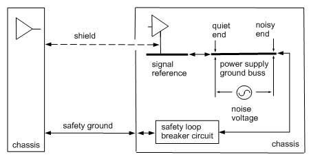
Figure 3.2-3, Safety Loop Breaker Circuit.
The Safety Loop Breaker Circuit, as explained in Rod Elliott’s
article, is a clever circuit that inserts a high impedance in the loop for low voltages, and a low impedance in the loop for high (fault) voltages. It is effective; however it attempts to ameliorate the symptom rather than eliminate the problem. The problem is twofold – the loop and the noise generator; so let’s address them. Figure 3.2-4 shows a better power supply solution.
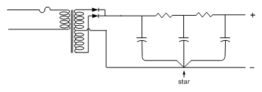
Figure 3.2-4, A clean power supply.
In figure 3.2-4, the internal ground buss is collapsed into a point, forming a local star ground. Bringing everything to a point forces us to make a connection to that point – no more multiple-point connection over which a noise voltage could form. Before, we had two connections: a high noise one connected to safety ground and a low noise one connected to signal reference. Note that now the high noise point is directly connected to the power common where it can be connected to safety ground to drain the AC leakage current, and the low noise point is directly connected to the power common where it can be connected to signal reference.
A power supply is a two-terminal output device – a voltage and power common. Do not make any external connections to internal points in the power supply. Of course, if the power supply produces both a positive and negative voltage output with a shared power common then it is a three-terminal output device.
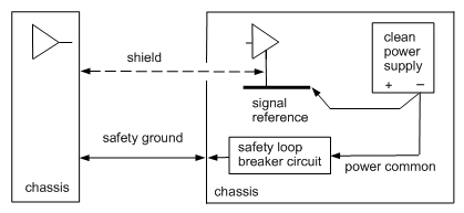
Figure 3.2-5, A clean power supply attached to the loop.
We have solved one source of Common Impedance Coupling but there is still another lurking. The next noise generator is the AC leakage current from the power transformer thorough the power supply to power common. In this case the Safety Loop Breaker Circuit may be detrimental. The Safety Loop Breaker Circuit will inhibit this current from reaching safety ground, and the current will take the path of least resistance through the signal reference and shield to find safety ground through the attaching device. Another problem is that the signal reference is not directly attached to the chassis so the chassis is not as an effective shield as it could be. I’ll come back to the appropriate use of a Safety Loop Breaker Circuit later but for now let’s get rid of it and attach the signal reference directly to the chassis.
Up until now we have looked at the Pin 1 Problem only on an input connection. Let’s now look at the problem from an output connection perspective.
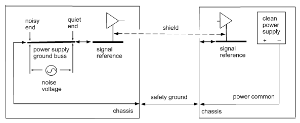
Figure 3.2-6, Pin 1 Problem on an output.
A Pin 1 Problem on an output really isn’t any different than a Pin 1 Problem on an input. As we are getting close to a final solution on the input side, let’s apply what we have found to the output side as well.
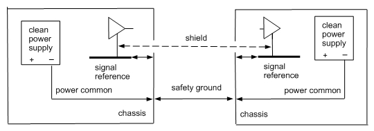
Figure 3.2-7, A clean power supply in both components.
Okay, the loop is shrinking and there is no longer any reason for the AC leakage current to choose the shield rather than the Safety ground. We have ameliorated the conductive coupling problem but we still have a radiated coupling problem so let’s take a look at that next. We still have the shield current going to the chassis through the signal reference. Figure 3.2-8 shows all of the different grounds connected together in a star of stars configuration.
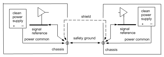
Figure 3.2-8, Star of stars.
It is now clear that the shield and safety ground no longer form a problematic ground loop and are now merely parallel paths.
Loops aren’t bad – it depends on what is on the loop. Unless there is a voltage generator to drive a current around the loop, or radiated current into the loop, it is merely a parallel path. Consider the parallel shields of a left and right channel stereo cable. However, parallel paths do form a loop antenna and can pick up RFI by radiated coupling. Therefore minimize the use of parallel paths to only where necessary and then minimize the area of the loop.
Speaking of RFI radiated coupling, it is possible for audio cabling and input circuitry to pick up RF noise. In extreme cases, shielding won’t resolve the problem and more aggressive techniques like RF filters on the audio inputs must be employed.
A Ham’s Guide to RFI, Ferrites, Baluns, and Audio Interfacing by Jim Brown is a particularly good coverage of filtering RFI.
There is still one thing left to address: Since it is certain that AC leakage current will flow through safety ground and the shield from both components, the two chassis and thus the two signal references will be at different AC potentials. This result s in signal noise: much less than we had with the Pin 1 Problem, but still some noise. We can reduce the voltage difference between the two chassis by reducing the impedance between them. First we use a larger safety ground wire in the power cord – the larger, the better. And of course you could even go to a hefty silver-wire power cord.
🙂 Second, use a shielded twisted pair for the interconnect cable, with one of the wires in the pair (as well as the shield) being the signal reference. If all of this is not enough, you could consider a Parallel Earth Conductor (PEC). A PEC is simply a heavy wire connecting the two chassis. Jim Brown calls this "local bonding" in
this article.
Figure 3.2-8 shows the star grounds on the chassis where the safety ground comes in. The star does not have to be there and it may be more convenient to move the star onto a PC board. A couple of examples of this are shown in figure 3.2-9.
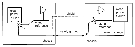
Figure 3.2-9, Some options for star grounding.
Let’s move on to the signal aspect of Interconnections.
3.3 – Balanced Interconnections: Signal
A signal interface is comprises of a signal and an associated reference. By definition, on a balanced interface the impedance to ground is the same for the signal and reference. Most balanced interfaces these days are implemented with electronic circuits, usually op-amps or similar integrated circuits. Classical balanced interfaces were implemented with audio transformers, and a few audio components still use transformers on their interfaces. Notice that the two lines on the interface are called “signal” and “reference.” These are different from the “signal reference” ground within the component.
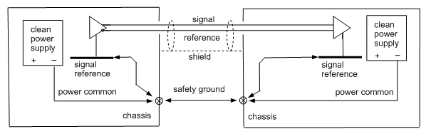
Figure 3.3-1, Balance interconnection with active circuits.
A cursory search will provide many available active chips for a balanced interface. Bill Whitlock goes into some of the circuits in his article
here.
There is one other issue to be aware of with a balanced interface when both ends have electronic circuits rather than a transformer on one or both ends. Even though a balanced input takes the signal between the two inputs without reference to a ground, it is important that the two inputs have a reasonably close potential to ground, otherwise the CMRR will suffer. Consider for a moment a tube differential amplifier with both its inputs to the grids at plus or minus 50 volts. In this extreme case the tubes would be either saturated or cut off. Thus, it is important to have an established ground reference between the sending and receiving components.
Audio Transformer
A transformer? Yes, a transformer. Transformers have received a bad rap for use in high-quality consumer audio equipment. They are said to be large and heavy, exhibit poor frequency response and distortion, and are expensive. As to the size and weight, we are talking line input and output transformers here, not tube amplifier output transformers. The Lundahl
LL1690 line input transformer is PC board mounted and is lighter and smaller than many high-quality film and foil capacitors that I use for coupling. As for frequency response and distortion, take a look at the Jensen
JT-10KB-D which is down -3dB at 0.5Hz (less than 1Hz folks!) and 180kHz, with less than 0.001% THD at 1kHz. These are just a couple of examples; both Lundahl and Jensen have several line transformers available to meet your specific needs. High-quality transformers are expensive; there is no getting around that. You get what you pay for and I suspect that most of the bad reputation has been generated by the use of cheap transformers. Bill Whitlock wrote the
audio transformer chapter of the Handbook for Sound Engineers that will give you an opportunity to understand audio transformers.
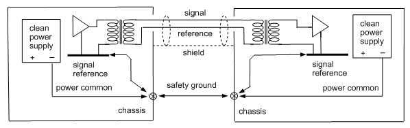
Figure 3.3-2, Balanced interconnection with transformers.
Okay, so what do you get with a transformer? Galvanic isolation and an excellent common-mode rejection ratio (CMRR) are the main things, but you can also get free gain or attenuation and along with that an opportunity for a lower output impedance. The primary advantage of a balanced transformer input versus a balanced active circuit input is a vastly improved CMRR. This is explained in section 3.2 of Bill Whitlock’s
Understanding, Finding, & Eliminating Ground Loops in Audio & Video Systems.
A good introduction to the advantages of balanced circuits and transformer interfaces is presented in
So You Thought Your Amplifier Was Balanced? by Andy Grove and Peter Qvortrup.
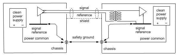
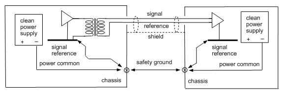
Figure 3.3-3
Figure 3.3-3, It doesn’t make any difference if one end of the connection has a transformer while the other end has an electronic circuit. The interconnection is the same for all varieties of balanced interfaces.
3.4 Single-ended Interconnections: Signal
The ubiquitous single-ended circuit is available on most audio components.
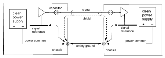
Figure 3.4-1 A single-ended interconnection using electronic circuits.
Most, if not all, single-ended output circuits will exhibit a DC voltage offset, meaning that the quiescent interface will be at a voltage level different from the reference, or shield. This voltage offset will produce a loud audible “thump” when the component is powered on. At best, the thump is startling and at worst it may damage a speaker. Also, some (not all) volume controls can be damaged by DC current over a long period. Therefore the designer of the output circuit will include a capacitor to block DC offset on the output. Because there are no standards addressing the interface, not trusting that the designer of the output circuit included a capacitor, the designer of the input circuit will also include a capacitor there. Being in series, the effective value of the combination of the two capacitors will be less than either alone. Therefore, unless the designers greatly oversized the capacitors, bass response may suffer. Also, the capacitors will interact with other impedances in the circuit, creating a low-pass filter; thereby affecting the high-frequency response. And of course, unless the capacitors are of the best quality, they will degrade the quality of the audio signal. There is a way to eliminate the capacitors.
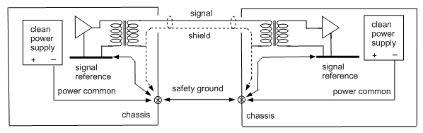
Figure 3.4-2, A single-ended interface using transformers.
A transformer is inherently a balanced device; however it can be used in a single-ended circuit by just grounding one side of a winding.
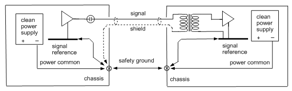
Figure 3.4-3, Single-ended interconnection with transformer input.
Figure 3.4-3 shows two components interconnected with a single-ended interface. The component on the right has a transformer input and notice that the shield, or reference, is connected to only the transformer and specifically is not connected to ground in that component. The only connection between the grounds in the two components is through the safety ground. The signal and shield that are connected to the primary winding of the transformer are connected to the driver and ground in the left hand component. Thus, even though the transformer is physically located in the right hand component, its primary winding and the cable are part of the output circuit of the output circuit in the left hand component. The signal connection between the components resides in the flux of the transformer and not in any wires. This is what is meant by “galvanic isolation.” Since there is only a single connection between the grounds in the two components (by the safety ground,) galvanic isolation precludes the possibility of any ground loops between the components. This completely eliminates the Pin 1 Problem. The capacitor on the output of the component on the left in the figure is still needed because, even though the transformer will block any DC offset, a DC offset may saturate a small input transformer.
You may provide an RF connection between the cable shield and the chassis on the right hand component by connecting a 10nF ceramic capacitor between the chassis and the shell of the RCA jack. Keep the leads as short as possible.
This same interconnection scheme could be used if both components had transformers on their interfaces; however, in that case it would make more sense to implement a balanced interface.
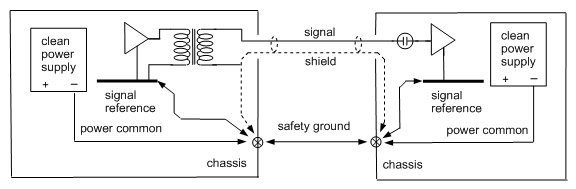
Figure 3.4-4, Single-ended interconnection with transformer output.
The transformer output shown in figure 3.4-4 is the mirror image of the single-ended transformer input shown in figure 3.4-3. However there is one important difference between the two configurations: the output amplifier in figure 3.4-3 has a low output impedance, while the input amplifier in figure 3.4-4 has a high input impedance. With a high input impedance, the attached cable and transformer primary winding is an antenna which picks up RFI noise. Grounding the shield at the source provides a low impedance and eliminates the problem. Therefore in this case, both ends of the interface must be grounded. Depending on the bias requirement of the input circuit, the input capacitor may not be needed.
3.5 - Mixed Interconnections
Sometimes you will have two components, one with a balanced interface and the other with a single-ended interface; and you wonder if there is a way you could interconnect them. Yes there is and we’ll go into that now.
Single-ended to Balanced Interconnection
The single-ended to balanced interconnection is pretty straight-forward, requiring that you only make a special cable. I’ll skip the cases where both components have transformers on their interfaces because in these cases it would be best to use a balanced interconnection.

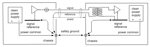
Figure 3.5-1, Single-ended to balanced interconnections.
In both of these cases the component on the left has a single-ended interface and the component on the right has a balanced interface. The only difference is that with a transformer in the right-hand component, a blocking capacitor is needed in the left-hand component. The capacitor is optional in the case of both components having electronic circuits on their interfaces. Even though the component on the right has a balanced input, the interconnection is unbalanced because it is referenced to ground.
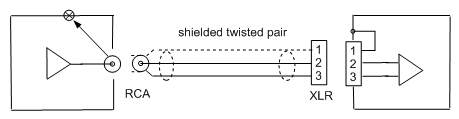
Figure 3.5-2 Single-ended to balanced interconnection cable.
You will need to make a special cable from a shielded twisted pair with an XLR connector on one end and an RCA connector on the other end. Pin 2 of the XLR connector is connected to the center pin of the RCA connector, and both pins 1 and 3 of the XLR connector is connected to the shell of the RCA connector. This is important; if pins 1 and 3 are connected together at the XLR connector end instead of at the RCA end, the noise rejection will be poorer.
Balanced to Single-ended Interconnection
The balanced to single-ended interconnection is more complex than the single-ended to balanced interconnection.
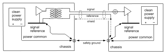
Figure 3.5-3, Balanced to single-ended interconnection with transformer output.
With the interconnect scheme shown in figure 3.5-3 we have a balanced output on the left, a single-ended input on the right with the two interconnected. Even though the component on the left has a balanced interface, the interconnection is unbalanced because it is referenced to ground.
In this case,
with a transformer output on the balanced interface, you can use an interconnect cable similar to that shown in figure 3.5-2. This cable is wired the same but the gender of the XLR connector is opposite of the cable shown in figure 3.5-2.
Most equipment that provide balanced outputs do so with differential amplifiers rather than transformers. The differential amplifier is most often two single-ended amplifiers, one with its signal inverted. When a single-ended output is desired, the negative output is not used, thereby loosing one-half of the signal, resulting in a 6dB difference in the output level between single-ended versus balanced operation. A transformer output does not exhibit this 6dB difference in signal level because the whole output signal is used for both balanced and single-ended operation.
Now let’s consider the case where both components have active circuits on their interfaces. This is where the complexity lies. A good explanation of the interconnection for balanced and single-ended components is given in Jensen’s
AN-003, and I will present a summary here.
I have purposely shied away from showing specific circuits in order to simplify the illustrations and also to suggest that the examples are generic. However it is important to know the type of circuit used for a balanced output driver if you want to connect it to a single-ended input. Some circuits want to have the unused output grounded while other circuits want the unused output left floating. Some circuits want the unused output grounded at the driver end while others want the unused output grounded at the far end. The wrong choice can degrade the sound or even damage the circuit. Rather than sort out all of the possibilities, I am going to side-step the issue and give you the best-quality solution. We know that a transformer input will accept any balanced output circuit and we know that a transformer can be used for a single-ended output, so let’s put those two together and use a transformer for balanced to single-ended conversion.

Figure 3.5-4, Balanced to single-ended interconnection.
An off-the-shelf version of this solution is the Jensen
ISO-MAX PC-2XR. This unit is specifically designed to interface between professional and consumer equipment. Professional equipment usually operates at a 12dB higher level than does consumer equipment, so the PC-2XR provides 12dB of attenuation to better match the devices.
We’ll come back to this, and similar devices for some solutions to the Pin 1 Problem.
Composite Interfaces
We can see that there is not a whole lot of difference between the configurations of a single-ended transformer input versus a balanced transformer input; likewise for a single-ended transformer output versus a balanced transformer output. Therefore, for the cost of an additional connector and a switch you can have both.
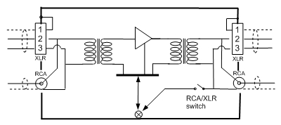
Figure 3.5-5, Balanced connection with single-ended connection.
The input transformer is connected to both an RCA jack and an XLR connector in parallel and the signal is provided through one or the other connector. If the input is single-ended, the ground for the shield is provided by the attaching component. The output transformer is also connected in parallel to both an XLR connector and RCA jack, providing the signal through one or the other connector. If a single-ended output is desired, a cable is connected to the RCA jack and a ground provided for its shield by closing the RCA/XLR switch. The switch is left open if the XLR connector is used to provide a balanced connection.
3.6 - Pin 1 Problem Remedy
Even though you employ all of the proper grounding practices in audio components that you build, you can still have a hum if you attach to a piece of commercial equipment that has a Pin 1 Problem. You have some choices in handling the problem.
First, you could modify the offending device so that it has a proper grounding scheme. Sometimes this is not practical because of the way the device is constructed so the next best thing would be to add a Safety Loop Breaker Circuit to the problem device.
But what if you have a piece of vintage classic equipment that you don’t want to modify in any way so as not to impact its resale value? The solution is simple if the equipment has a balanced interface – merely open the shield at the receive end of the interconnect cable. As shown on page 27 of this
article, it is important to open the shield at the receiving end rather than the sending end to maximize CMRR. You might want to experiment with placing a 10nF capacitor from the shield to the chassis. Keep the leads as short as possible.
If the offending equipment has a single-ended interface you can turn to a transformer to solve the problem. As discussed
here, Jensen has a complete line of isolators similar to the ISO-MAX PC-2XR that can interface any type of connection to any type of connection while breaking the problematic loop.
It is always better to solve the problem in the offending device (by modifying it) or on its interface (with transformer isolation) rather than to compensate for the problem in the equipment that the offending device is attached to. We’ll see why this is when we cover interconnecting equipment that use a Safety Loop Breaker circuit for isolation and also in the section on ground isolation.
3.7 - Effective Interconnection Schemes
In this section I will present four interconnection schemes that should cover just about every situation. I’ll be using some terms rather loosely so I’ll define my usage here:
- Class 1 device – This is an analog component that has its chassis connected to safety ground and does not have a Safety Loop Breaker Circuit or a Pin 1 Problem. It does have single-ended non-galvanically isolated interfaces.
- Class 2 device – This is a commercial analog component that is designed to be safe with no connection to safety ground. It has single-ended non-galvanically isolated interfaces. An example of a Class 2 device is any component that has a two-prong power plug, or is battery powered, like a laptop computer.
- SLB device – This is an analog component that has its chassis connected to safety ground and has its system star ground isolated from the safety ground by a Safety Loop Breaker Circuit.
- Pin 1 Problem device – This is an analog component that has its chassis connected to safety ground and does have a Pin 1 Problem. That is, it has a poorly chosen grounding system that injects noise into the ground system. Most, if not all, tower computer (not laptop) sound cards have a Pin 1 Problem.
- Computer – This is a catch-all for any kind of digital audio device that has digital power supplies dumping a lot of noise into its ground system. An example is an SPDIF interface from a computer or a satellite TV system.
The first effective grounding scheme is a system with all Class 1 components shown in figure 3.7-1. This is the grounding scheme that we developed in section 3.2. This interconnection scheme has a single-level ground system with all of the signal shields and safety grounds connected to the system star grounds.
This scheme is the only one of the four that allows noise from the power line in the form of AC leakage current to flow in the signal ground system. That noise will be transferred from the primary of the power transformer through the parasitic capacitors to both the core and frame of the power transformer as well as power common as shown in the Juaneda
article and also Jensen
AN004. However, since the whole ground system has a low impedance, the level of the noise will be low and should not be a problem. If it is a problem, the impedance can be reduced using Parallel Earth Conductors (PEC) or “local bonding” as described by Jim Brown
here.
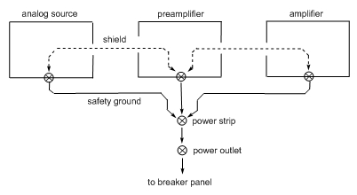
Figure 3.7-1, Simple system of Class 1 components.
The second effective grounding scheme is a system with all Class 2 components as shown in figure 3.7-2. This interconnection scheme has a single-level ground system with all of the signal shields connected to the system star grounds.
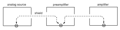
Figure 3.7-2, Symple system of Class 2 components.
This scheme does not have a problem of noise from the power line in the form of AC leakage current because the ground system is not connected to safety ground and thus there is no return path for the leakage current. Without a path, there can be no current. And of course, because there is only one connection between the components – the shields, there can be no ground loops.
The third effective grounding scheme is a system with all the components having
Safety Loop Breaker Circuits as shown in figure 3.7-3. This interconnection scheme has a two-level ground system with all of the signal shields connected to the system star grounds forming the first level. All of the safety grounds are connected to the chassis forming the second level. The two ground levels are isolated from each other by Safety Loop Breaker Circuits.
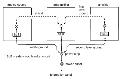
Figure 3.7-3, Simple system of SLB components.
This scheme does not have a problem of noise from the power line in the form of AC leakage current because the first-level ground system is isolated from safety ground and thus there is no return path for the leakage current. Without a path, there can be no current. You can think of the first-level ground system as the same as the ground system in the Class 2 ground scheme. However, AC leakage current that has been injected onto the chassis from the transformer does flow in the safety ground circuit.
Of course, no grounding scheme is very useful if it is restricted to having only one type of component in the system. So let’s see how we can mix different types of components in a ground system. We’ll start simply with just two interconnected components and then expand the grounding to cover several components.
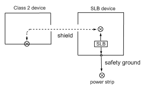
Figure 3.7-4, Interconnection of a Class 2 device with an SLB device.
As mentioned above, the first-level ground of an SLB device is the same as the ground in a Class 2 device so they interconnect without any problem.
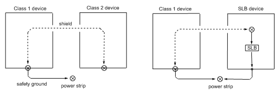
Figure 3.7-5, interconnection of a Class 1 device with either a Class 2 device or an SLB device.
There is no ground loop in either of these cases; however AC leakage current from the power transformers in the Class 2 and SLB devices is directed to earth through the shield and safety ground in the Class 1 device. If this is a problem, the only recourse is to isolate the safety ground in the Class 1 device from the class 2 or SLB device. This may be achieved by either adding an SLB circuit to the Class 1 device (thereby making it an SLB device) or galvanically isolating the interconnection with a transformer.
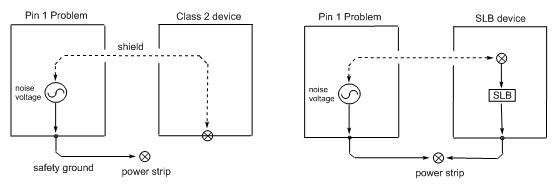
Figure 3.7-6, Interconnection of a Pin 1 Problem device with either a Class 2 device or an SLB device.
There is no ground loop in either of these cases so the Pin 1 Problem is remedied; however, just as with the Class 1 case above, AC leakage current will flow through the shield. This may present more of a problem with a Pin 1 Problem device than with a Class 1 device because the AC leakage current will flow through the signal reference before being directed to the safety ground. The solution is the same as that of the Class 1 device above.
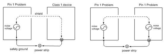
Figure 3.7-7, Interconnection of a Pin 1 Problem device with either a Class 1 device or another Pin 1 Problem device.
This is the classic case of a Pin 1 Problem that was discussed in detail in chapter 3.2. The solution is to either: modify the Pin 1 Problem devices so that they no longer exhibit a Pin 1 Problem, or add an SLB circuit to the Pin 1 Problem device, or galvanically isolate the interface with a transformer. This is illustrated in figure 3.7-8.
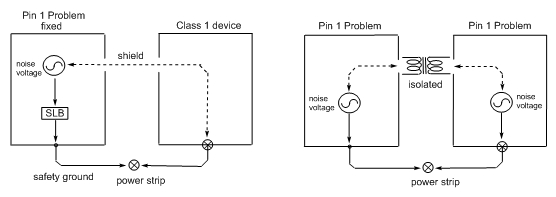
Figure 3.7-8, Solution for the Pin 1 Problem device interconnection.
Since the Pin 1 Problem injects noise into the ground system, the most effective way to include such a component is to galvanically isolate it from the rest of the ground system. The same solution effectively allows a computer sound card to be attached to an audio system. The galvanic isolation for these devices can be incorporated into the components or provided as separate, external devices, such as the Jensen
ISO-MAX.
In the case of the computer, since a computer sound card is not in the realm of the highest quality audio devices, there is no need to spend the money on the highest quality line transformer to provide galvanic isolation. EDCOR has a line of very good line input and output transformers that will serve well in this application.
Attaching a computer sound card to the SLB grounding scheme presents the same problems as in attaching a computer sound card to the Class 1 grounding scheme. The best and total solution is galvanic isolation. However, for a very simple system as shown in figure 3.7-9, directly attaching the computer sound card to the SLB isolated amplifier may provide an acceptable solution. The SLB will inhibit the ground loop. You will still have the problem of AC leakage current from the amplifier flowing through the computer but, since the computer sound card as a poorly chosen ground structure, it may not matter.
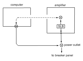
Figure 3.7-9 A simple SLB system.
However, if the computer is a laptop then there is no need for the galvanic isolation because the laptop does not have a connection to the mains power and therefore no ground loop.
There is one additional problem to take care of here – the dirty safety ground on the computer. We do not want to mix this dirty safety ground with the relatively clean safety ground of the audio system so provide a separate AC mains branch circuit for the computer.
Okay, let’s summarize where we are with the interconnections of two devices:
- There is no problem interconnecting devices of the same type: Class 1, Class 2, or SLB.
- There is no problem interconnecting a Class 2 device with an SLB device.
- There is a minor problem of AC leakage current when interconnecting a Class 1 device with either a Class 2 device or SLB device.
- There is a minor problem of AC leakage current when interconnecting a Pin 1 Problem device with either a Class 2 device or SLB device. The major “Pin 1 Problem” is remedied.
- There is a major “Pin 1 Problem” when interconnecting a Pin 1 Problem device with either a Class 1 device or another Pin 1 Problem device.
- A Safety Loop Breaker circuit helps a lot and may provide an adequate solution.
- A transformer will provide isolation, solving the Pin 1 Problem and the AC leakage problem.
Let’s move on to interconnecting three or more devices. Again, as long as all of the devices are of the same type: Class 1, Class 2 or SLB, three or more can be interconnected without a problem. A mix of Class 2 and SLB devices may be interconnected without a problem. Problems arise when Class 1 or Pin 1 Problem devices are introduced into a Class 2 or SLB grounding system. When there is only a single Class 1 or Pin 1 Problem device in the system, the situation is the same as for interconnecting two devices as discussed above. It gets interesting when two or more Class 1 or Pin 1 Problem devices are introduced into the Class 2 or SLB grounding system.
When we directly attach a Class 1 device to a Class 2 ground system we cause the whole ground system to be connected to safety ground, thereby loosing the inherit ground isolation in a Class 2 system. When we directly attach a Class 1 device to the SLB first-level ground system, we cause the first-level ground system to be directly connected to the second-level ground system. This nullifies the benefit of all of the Safety Loop Breaker Circuits in the system. We now have what amounts to a Class 1 grounding system. We don’t have an immediate problem because we don’t have a noise generator in any loop. We do have a problem waiting to happen when a Pin 1 Problem device is added to the system. This is shown in figure 3.7-10.
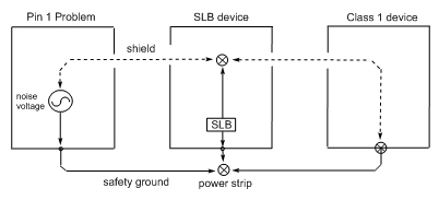
Figure 3.7-10, A ground loop bypassing the SLB circuit.
The ground loop flows between the Pin 1 Problem device and the Class 1 device, bypassing the SLB circuit. The noise voltage is impressed on both the shield from the Pin 1 Problem device as well as the shield to the Class 1 device. Things can get pretty complex and this figure doesn’t even hint at the complexity. The SLB device can actually be several interconnected SLB devices and the Class 1 device can be anywhere in the system – an input or an output. The ground loop problem can be hard to diagnose. For example, say you had a system comprised of all SLB devices except for a single Pin 1 Problem device. There is no problem because the SLB isolation is intact and the ground loop is broken. Now, you buy a new component that happens to be a Class 1 device and install it in the system. Now you have hum that you didn’t have before. You take the new component out of the system and the hum goes away. You would have reason to suspect that something was wrong with your new component, while the problem is really caused by that Pin 1 Problem device that had been in your system all along. Bill Whitlock’s article
Understanding, Finding, & Eliminating Ground Loops in Audio & Video Systems contains some great techniques that you will need to isolate the problem device.
Thinking that if one Safety Loop Grounding circuit is good, two would be better, some designers separately isolate the component input and output, each with its own SLB circuit. This does isolate the input from the output but unfortunately comes with the cost of increasing the ground noise within the component. We’ll see how this happens in the section on Ground Isolation.
Often the preamplifier is the central component in the audio system, with a single output and many inputs. If both the preamplifier and amplifier are SLB devices, you can ensure that there can be only one Class 1 or Pin 1 Problem device in the system at any time by switching the input grounds along with their associated signals.
Other than that, we are back to galvanically isolating the problem component with a transformer.
I know that you have been wondering about the forth scheme and thinking that there are three kinds of people – those that can count and those that can’t count. Well there really is a forth system and it is the ultimate solution for system grounding. This solution, which is shown in figure 3.7-11, is centered on a preamplifier that has all of its input and outputs galvanically isolated. Since everything is galvanically isolated, it doesn’t matter what is connected to the preamplifier. You can mix Class 1, Class 2, SLB, Pin 1 Problems, and computers – none of the grounds are interconnected. The preamplifier may be a Class 1 or a Class 2 or an SLB device, although it really doesn’t make any sense to make it an SLB device because there is no reason to break the safety ground circuit. Notice that the computer is plugged into a separate branch of the mains power to reduce the earth noise in the system.

Figure 3.7-11, A grounding scheme centered on an isolated preamplifier.
Did I say that there were four schemes? Well there is really a fifth. That is a scheme where the isolated preamplifier scheme is turned inside-out with all of the attaching components having galvanically isolated interfaces. In this case, the preamplifier does not need to have isolated interfaces. The attaching devices may be Class 1, Class 2, or computers. They cannot have a Pin 1 Problem because of their galvanic isolation. Again, it doesn’t make any sense to have a galvanically isolated device further isolated with a Safety Loop Breaker Circuit. I currently use this grounding scheme in my personal audio system. This scheme is shown in figure 3.7-12.

Figure 3.7-12, A grounding scheme involving isolated devices.
3.8 Cables
Cables are a science of themselves and to get an idea of some of the complexity involved, you can read
Pin 1 Revisited by Jim Brown,
SCIN, also by Jim Brown and chapter 9 of Morrison [1]. However the good news is that in the relatively benign environment of the home and with short cables used in home audio installations, cables do not need to be a critical factor. I will touch on a few important factors though. Cables both radiate energy and are affected by EMI from other devices. EMI has two components, an electric field and a magnetic field, and there are different aspects of a cable that will effectively counteract both of these fields. Electric fields are blocked by the cable shield and a good shield for that is the woven copper type - the tighter the weave, the better. A twisted pair of wires is relatively immune from a magnetic field, so you will want to use shielded twisted pair for all of your cables. This is even good for the power cable, although you will want heaver wire for this application. Another important factor is the DC resistance, or low-frequency impedance of the ground wires – we want that as low as possible. We saw why this is important back in chapter 3.2 when we interconnected the components.
3.9 - Other Interconnections
My mother used to say, gesturing at something I had found, “Don’t touch that, you don’t know where it has been!” Digital audio signals are kind of like that – you don’t know where they have been. Often the source of the signal will have a switching power supply that is dumping tons of noise into the ground system. Examples would be a computer or video system. For best results, the digital system should be isolated from the audio system as much as possible for both power and signal. Each should be powered from separate power line branches. The isolation for the signal will depend on what the interface is. As poor as a Toslink is for many reasons, it does provide galvanic isolation. An SPDIF or AES interface should be isolated with a pulse transformer. A USB interface is a little tougher. If you are designing your own interface, you can use opto-isolators or GMR isolators, or convert the interface to SPDIF and use a pulse transformer. I haven’t used any, but there are plenty of external USB isolation devices available. Thomas Kugelstadt’s article, “
When good grounds turn bad!” is a good overview of the problem of interfacing with digital devices and what you can do to alleviate the problem. Although the article uses an RS-485 data link for an example, the concepts are valid for any digital interconnection scheme.
Even the analog signals have problems: according to Jim Brown in his
RFI article “Virtually all computer sound cards have Pin 1 Problems.”
Cable TV is another problem area for causing hum in an audio system. Almost all cable grounds are at a different level than the mains safety ground and need to be isolated with an RF isolator. Satellite TV systems can also cause a problem and need to be isolated, however these need a different type of isolator from the CATV isolator. A search of the internet will turn up lots of options.
3.10 - Interconnection Summary
- Provide a dedicated branch power line, or at least a benevolently loaded one, for audio components.
- Plug all audio components into the same power strip or power outlet.
- Provide a separate branch power line for computers, TVs or any other devices having switching power supplies.
- Provide isolated interfaces for connections between:
a. The audio system and other devices, like computers or TVs.
b. Pin 1 Problem devices and any other audio component.
c. Class 1 component and a class 2 component. Isolation may not be needed for this case.
d. Class 1 component and an SLB isolated component. Isolation may not be needed for this case.
- Loops aren’t bad – it depends on what is on the loop.
- Use shielded heavy gauge twisted pair interconnect cables.
- Make a map of your system grounds.
Understanding, Finding, & Eliminating Ground Loops in Audio & Video Systems by Bill Whitlock has a lot of great information on solving interconnection problems in audio systems.
Chapter 4 – Ground Structure within a Component
So far, for simplicity I have included only a single signal reference and power supply in each device. However, most components are comprised of several circuit boards, each with its own grounding scheme incorporating busses or stars on them. These are then interconnected, together with one or more power supplies and the chassis. This can get quite complex and it is a good idea to make a map of the ground structure and power structure when designing a piece of audio equipment. Individual grounds and power lines should be routed as carefully and purposely as the audio signals.
In a nutshell, a problem can occur when two grounds share the same conductor (perhaps by necessity) or something is connected to the wrong ground. System grounding may be established using a star structure, a star-of-stars, a buss arraignment or a combination of those. Many problems are eliminated when every ground is connected to a single point – star grounding. However, this is often impracticable: The best we can hope for is a star-of-stars approach with individual stars connected.
It’s all about controlling the paths – ground current (of any kind) should go only where it is needed. Likewise, power current should go only where it is needed.
4.1 - Grounding Rules
Here are some rules to help you plan your grounding structure. The first four rules are from what we learned about interconnecting equipment.
Rule 1: Each of the following must be connected to the system star ground by one and only one route.
- All signal references
- All power commons
- Shields of non-galvanically isolated single-ended inputs and outputs
- Safety ground and chassis. The safety ground and chassis should be thought of as a single entity.
- The connection may be direct, or indirect through a star-of-stars or buss. This is expanded upon below.
- The safety ground and chassis may be connected to the system star ground through a Safety Loop Breaker Circuit.
- The “one and only one” part of this rule precludes ground loops. There is no excuse for a ground loop within a single component.
Rule 2: The shield of a balanced input or output (XLR pin 1) must be connected to the chassis at or as close as is possible to the connector.
Rule 3: The shield of a single-ended input or output that is not galvanically isolated must be directly connected to the system star ground.
The shield is the signal reference in the cable.
Rule 4: Any circuit associated with an input or output that is not galvanically isolated must have its signal reference directly connected to the system star ground.
Rule 5: The mains safety ground must be directly connected to the chassis.
From
IEC 60950, “The wire is terminated with a closed loop connector which is fixed to the earthing stud or screw with a star or lock washer and a nut. Other parts of the product that need to be earthed are connected by closed loop connectors to the same stud and locked with an additional nut. It is important that the earth wire from the power supply cord is located at the bottom of the stud and locked with its own nut. The earthing stud must not be used for any purpose other than earthing. It cannot be used, for example, for the mechanical fixing of parts other than the earth conductors. Its mechanical structure must also be such that it cannot be loosened from outside the device. For example, it cannot be a post fixed with a screw from outside the product.”
Rule 6: Each signal reference must be directly connected to its power reference.
That is, no circuit may have its signal reference connected to its power common through another circuit’s signal reference or power common. This rule allows for a star-of-stars with the signal reference and power common directly connected together in a star and that star connected to the system star (either directly or through a buss).
Rule 7: Circuits may be grouped together with their signal references forming a buss.
The order of the grouping is not arbitrary. Just as the signal is routed along, stage to stage, the associated signal reference can be routed with the signal between stages. Keep the signal and its associated signal reference electrically close together; they should be treated as a pair. This minimizes the risk of noise being injected into the signal reference.
One end of the buss should be connected to the system star ground, either directly or by a star of stars.
4.2 - Grounding Examples
Now let’s take a look at some examples.
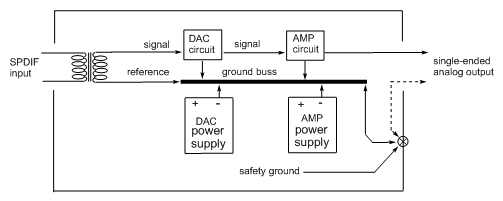
Figure 4.2-1, An example of proper ground routing with a ground buss.
Figure 4.2-1 shows a Digital to Analog Converter (DAC) with an SPDIF input and single-ended analog output. Each of the power supplies has a single power common output and each of the circuits has a single signal reference output; all connected to a ground buss. Thus we have a buss of stars which in turn is connected to the system star ground. The order to which each attachment is made to the buss is important, flowing along with the signal from input to output. Notice that none of the Grounding Rules are violated. In an implementation of this example, there may not be a separate physical buss that can be identified. Rather, the buss is formed from ordinary printed circuit traces and regular hookup wire between PC boards. It is the structure that creates the buss.
Figure 4.2-1 also shows separate power supplies for the DAC and the amplifier. The DAC is mostly digital electronics that tends to reflect digital switching noise back into its power supply, particularly on the power common. Therefore it is a good idea to keep this power common separate from analog signal references or the power common of analog supplies.
Now let’s change one thing and see what happens. I am not an advocate for an SPDIF interface without a pulse transformer, but there are plenty of them out there so for this example I will remove the transformer and bring the SPDIF interface directly into the DAC.
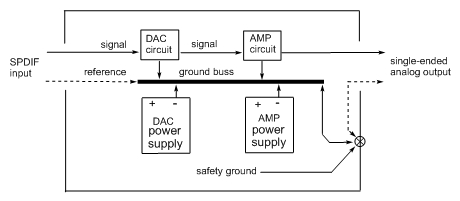
Figure 4.2-2, A poorly-chosen grounding scheme.
I’m sure that you see that we now have a Pin 1 Problem. Rule 3 is broken by connecting the input shield to the buss rather than to the system star ground. Rule 4 is broken by connecting the DAC circuit signal reference to the buss rather than directly to the system star ground. Okay, let’s fix the grounding so that those rules are not violated.
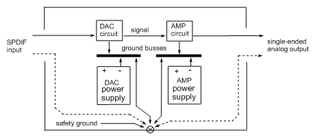
Figure 4.2-3, A well-chosen grounding scheme.
In fixing those two things we have transformed the grounding structure into a star-of-stars. This illustrates an important concept – any device that has both single-ended inputs and outputs (that are not galvanically isolated) cannot use a ground buss structure. This is because the signal references for both the input circuit and output circuit must be directly connected to the system star ground and adding a ground buss between them would form a ground loop. Another example of such a component is the ubiquitous single-ended preamplifier. Grounding problems with a preamplifier may well be the source of the myth that a star-of-stars is the only acceptable grounding scheme.
Let’s take a look at another example, this time a power amplifier. Using a ground buss structure in a power amplifier has been around for a long time and is popular with Japanese amplifier constructors.
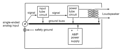
Figure 4.2-4, a power amplifier using a ground buss.
The first thing to notice is that the shell of the input RCA jack is not isolated from the chassis. Rather, it is effectively the system star ground. The order of attachment to the buss is important with the buss starting at the input jack and ending at the negative speaker jack. The quietest circuits are connected closest to the input jack, with the progressively noisier circuits towards the speaker jack. An implementation of this example will have a readily identifiable buss, usually a very thick bare solid copper wire. An example of this technique can be seen
here.
All of this is not to argue that a ground buss is superior to a star ground or vice versa, rather both are tools that can be effectively used in an appropriate situation. Stars are easier to implement because you don’t have to worry about the order of connections like you must on a buss. Further information on implementing star grounds and ground busses is in Randall Aiken’s article
here.
4.3 - Power Supply Chassis
When should you put the power supply and amplifier in separate chassis? First of course is if the unit is physically too large for a single chassis. The second reason is for noise immunity - for example, a phono preamplifier with a sensitive input stage. Or perhaps you have a huge power transformer that is radiating a large magnetic field and you need to physically separate it from the amplifier. There is no grounding reason to have separate chassis.
The next question is – how should they be separated? The answer is simple; and obvious if you think about it. Even though the two devices are physically in two chassis, they should be thought of as two parts of a single chassis interconnected with a cable. Design your grounding and make a map of the grounding and power on a piece of paper. Then draw a line around what you want in the power supply chassis (or vice verse, what you want in the amplifier chassis). Anything that crosses the line is in the cable. This is shown in figure 4.3-1. The cable shield extends the chassis shield between the two chassis and should be connected to each chassis at or as close as possible to the connector. The safety ground wire in the cable is connected to each chassis at its system star ground, thereby extending the safety ground function to the second chassis. Be careful of the routing of the safety ground wire that connects the two chassis – it should take as direct a route as possible and lie close to the chassis. Use a connector with a pin that makes first and breaks last for the safety ground. It would be a good idea to use a twisted pair for the wires containing power and power common to cut down the susceptibility to radiated magnetic EMI.
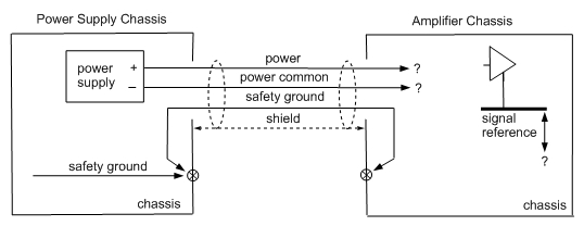
Figure 4.3-1 A separate power supply chassis.
The power supply chassis may contain more than one power supply. Each power supply should have individual power and power common lines with each power common connected to its destination in the amplifier chassis. The destination may be a star ground, a ground buss or an individual signal reference. The alternative of connecting all of the power common lines to the star ground in the power supply chassis and then running a single shared power common wire to the amplifier suffers from Common Impedance Coupling. Also, you may want the different power common wires to go to separate places in the amplifier.
A power supply chassis can service more than one amplifier chassis. In this case a cable with the complete set of power, power common, safety ground and shield, should run between the power supply chassis and each amplifier chassis. If a power supply in the power supply chassis serves two (or more) amplifier chassis, its power common should be connected to the destination in each amplifier chassis.
4.4 – Input Switching
There was a time when it was the vogue to switch both wires, signal and ground, of single-ended inputs. I don’t know where this came from – perhaps it was just a copy-cat of switching balanced inputs. Or perhaps it was an attempt to keep a myriad of dirty grounds from corrupting the signal reference. In any event, now that we have cleaned up the grounds, it may not necessary to switch the grounds. However there still are a couple of cases where switching both the ground and signal may help:
Switching the grounds helps with cross-talk and bleed-through between the inputs. Cleaning up the grounds should help this. If there is still a problem you can connect (with a relay) a 50 Ohm resistor between the signal and signal reference of all inputs except that which is selected.
AC leakage current flowing through the interconnect shield may pose a problem, particularly in Class 2 and SLB devices. Remember, when the interconnect shields are not switched, all of the grounds in the system are connected together in a mesh.
4.5 – Input Jacks
The RCA jack of a single-ended connection is usually isolated from the chassis and the shield is connected to the star ground. It may be beneficial to connect a 10nF ceramic capacitor from the shell of the RCA connector (shield) to the chassis. This provides a direct path for RF noise from the shield to the chassis right where the shield enters the chassis.
4.6 – Volume Controls
Volume controls are potentially a source of hum and noise from two causes: first, by radiated coupling into the resistive element, and second, by inappropriate choice of circuit connections. The radiated coupling is easily solved by ensuring that the body of the control is grounded to the chassis through its metal mounting bushing.
Volume controls on non-galvanically isolated interfaces are unique in that they are in the output circuit of one component and also in the input circuit of another component. They work by common impedance coupling between the two circuits. Therefore keep in mind that there are two separate signal loops, an input signal loop and an output signal loop. It is important to keep the two loops separate in the grounding system. This is best accomplished by connecting the reference end of the volume control potentiometer to the system star ground.
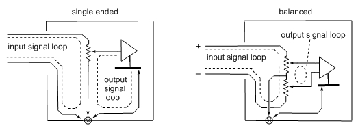
Figure 4.6-1, Volume controls on a non-isolated input.
When the input is galvanically isolated it is no longer necessary to connect the volume control to the system star ground. It should be considered as part of the amplifier circuit and referenced to the signal reference of that amplifier.
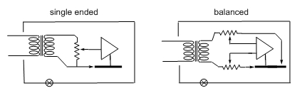
Figure 4.6-2, Volume controls on isolated inputs.
4.7 - Grounding Transformers
Different kinds of transformers have different grounding requirements. Sometimes a transformer will have an internal shield between the windings and this will give you a hint how the transformer should be grounded. The shield is to inhibit capacitively coupled AC leakage current between windings and between windings and the frame. Sometimes the shield is connected to the frame and other times it has a separate wire. What is on the winding being shielded will tell you where to ground the frame and the shield. The idea is to get the AC leakage current noise back to where it came from in as short a path as possible. So, for example, the AC leakage current from the primary of a power transformer came from the mains power line and should be returned to earth, so the transformer frame should be connected to the safety ground.
The frame of the power transformer in a class 1 component (with chassis connected to safety ground) must be connected to safety ground - just make sure that there is a good contact between the transformer frame and the chassis. It doesn’t make sense to ground the power transformers in a class 2 component because since there is no connection to safety ground, there is nowhere to bleed the AC leakage current. Also, perhaps the transformer is not intended to be grounded as part of the isolation design. Therefore, grounded or ungrounded, the power transformer in a class 2 device should be left as it is.
Some audio output transformer circuits provide better performance with the transformer frame grounded while others work better with the transformer frame ungrounded so you will need to experiment to determine which is better for a particular case. The leakage current in a power amplifier output transformer came from the output stage power supply and thus, if the transformer is to be grounded, the frame should be isolated from the chassis and a wire attached to the frame should be returned to the power common of that output stage.
Speaking of output transformers, the negative terminal of the output should be connected to the power common of the output stage.
The output windings of line output transformers and the input windings of line input transformers don’t need to be grounded. Looking back on the chapter on transformer coupled interfaces; you will remember that grounding one side of the interface creates a single-ended interface and the grounding schemes are covered there.
Some line interface transformers have a center tap which may be grounded for a balanced interface. I would recommend grounding the center tap of only the sending end – grounding both ends may create a ground loop. Even though the primary winding is from the output driver, I would not recommend grounding the center tap to the output drive power common because this would allow the possibility of a Pin 1 Problem if the other end were also grounded. Rather, I would recommend using the system star ground in this case.
4.8 – Ground Isolation
Some people believe that it is necessary to isolate the system star ground from the chassis and safety ground in order to have a hum-free audio system. However, if all of the components in the system have their grounding implemented properly, there is absolutely no need for ground isolation, Although isolating the grounds may eliminate a ground loop, it does come with two penalties: First, since the signal reference is not directly connected to the chassis, the chassis is not an effective shield for the electronics. Second, since the power common is isolated from the safety ground and connected to the signal reference, any AC leakage current from the power supply may flow through the signal reference to get to the safety ground in another component.
If you must isolate the grounds; never, ever, for any reason, disconnect a safety ground or fail to provide a safety ground in any equipment that you build. First, it is unsafe and second, there are equally effective methods of isolating grounds that do not come with the safety hazard. Figure 4.8-1 shows two such methods.
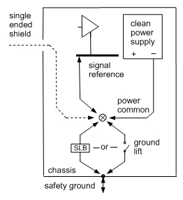
Figure 4.8-1, Ground isolation
First is to provide a “ground lift” switch between the two grounds to be isolated. This does such a good job of isolating the grounds that it precludes current from an electronic short circuit from blowing a fuse. This is illustrated in figure 1-3.
A better solution is to provide a
Safety Loop Breaker Circuit (SLB). This circuit will allow the current from a fault to flow to the chassis and also provide ground isolation under normal, non-fault conditions. In his article, Rod Elliott states that a Safety Loop Breaker Circuit may not be legal in some places so you should check this out before you use this circuit.
The best solution for ground isolation is to employ galvanic isolation on problem interconnections.
A component with a properly designed grounding system will not have any internal ground loops. Therefore, there is never any reason to isolate grounds within a component.
Let’s take a closer look at how the Safety Loop Breaker circuit works to see why I say it is a third choice, behind fixing the ground loop problem or galvanically isolating the ground loop with a transformer. I’ll start with dissecting the problem so as to better understand what is going on.
Ground Loop Suppression
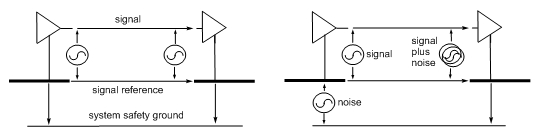
Figure 4.8-2
Figure 4.8-2, The ideal, as shown in the left hand circuit, is to have the signal transferred unchanged from the sending circuit to the receiving circuit. However, if there is noise in the system, as shown in the right hand circuit, the signal reference rides on the noise and the sum of the signal plus noise is presented to the receiving circuit.
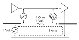
Figure 4.8-3, Showing how the noise is added to the signal by common impedance coupling.
Let’s say, for example, that the interconnect shield connecting the two signal references has an impedance of 1 Ohm and the level of the noise is 1 Volt. The 1 Volt across 1 Ohm will cause a noise current of 1 Amp to flow, and the 1 Volt of noise will be presented to the receiving circuit. Note that I refer to the impedance in the loop rather than the resistance in the loop. This is because the noise spectrum is spread across a wide frequency range and the impedance at higher frequencies is often more significant than the resistance. For simplicity, I assume for all of these examples that the noise source has an internal impedance of zero Ohms. Of course it will have a (very low) finite impedance of some internal ground wiring. Refer to Chapter 3.1 for an example of a noise generator.
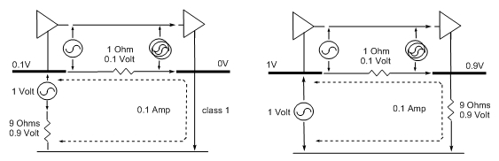
Figure 4.8-4, Adding impedance to the noise loop.
In this example I have added 9 Ohms of impedance to the noise loop for a total of 10 Ohms of impedance. The impedance may be added in the component with the noise or in the attaching component. The noise voltage is still 1 Volt; however the 1 Volt across 10 Ohms of impedance causes only 0.1 Amp of noise current in the loop. The 0.1 Amp of current through the 1 Ohm impedance of the interconnect shield develops only 0.1 Volt of noise to be presented to the receiving circuit. We have thus reduced the noise that the receiving circuit sees by a factor of ten. Note that none of the noise has disappeared; the remaining 0.9 Volts of noise is dropped across the added 9 Ohms of resistance. There is an important difference between the two circuits in figure 4.8-4. In the left hand circuit, the added impedance is under the noise source so that signal references are close to safety ground; therefore the noise voltage on the ground system is low. One signal reference (being a class 1 device) is at ground while the other is 0.1 Volts above ground. In the right hand circuit, the added impedance is in the attaching component so that the signal references are raised above ground. One signal reference is 1 Volt above ground while the other is 0.9 Volts above ground. In both cases there is 0.1 Volts between the signal references but the left hand circuit has a much lower ground noise. The noise on the ground system is not important to this one signal because it is common mode, but noise on the ground system may become a problem if other connections in the system allow this noise to flow to other areas. We’ll see some examples of this later. Although it is a trade off, it is best if noise on the individual signal as well as noise on the ground system are both kept as low as possible. Therefore, when there is a choice, it is better to install the added impedance in the circuit containing the noise source. We have been talking about isolating grounds; however we really are isolating the noise generator – the ground isolation is an artifact of that.
Thus the conclusion is that the added impedance helps reduce the noise by inhibiting the noise current in a ground loop; however it does not eliminate the problem as would galvanic isolation or fixing the ground loop problem. None of the noise is eliminated – it is just moved to a part of the circuit where it will have less of an impact on signal.
Well, if 9 Ohms is good, why not add 90 Ohms or 900 Ohms of impedance? This would further reduce the noise level; however there is another, more important, factor to consider – that of safety. If an electrical fault occurs there can be a very high voltage present across the impedance. We need to keep the ground impedance low so that most of the fault current will flow through the ground circuit rather than through an external route, for example, a person.
Safety Loop Breaker Circuit
The Safety Loop Breaker circuit presented in Rod Elliott’s
article addresses this issue of ground noise differently. Instead of adding impedance to the ground loop, Rod’s circuit subtracts voltage from the point in the circuit where it is inserted. This is accomplished with a pair of diodes (inside a bridge rectifier) in parallel opposition; that is, the anode of each is connected to the cathode of the other. These diodes prevent the voltage across the Safety Loop Breaker circuit from being greater than 1 diode voltage drop (0.6 Volts). As with the simple resister example shown above, none of the noise has disappeared: the diodes will drop 0.6 Volts and any remaining noise (over the 0.6 Volts) is distributed across the impedance in the circuit. If the voltage across the circuit is less than 0.6 Volts, then the diodes will not conduct and the circuit works by adding impedance to the loop with a 10 Ohm resistor across the circuit. This resistor also limits the impedance between safety ground and the internal ground buss. Also, In the event of an electrical fault that places a high voltage on the internal ground buss, the diodes will keep the voltage on the buss from exceeding 0.6 Volts. There is a 100nF capacitor across the circuit to reduce RFI problems. Let’s take a look at how all this works.
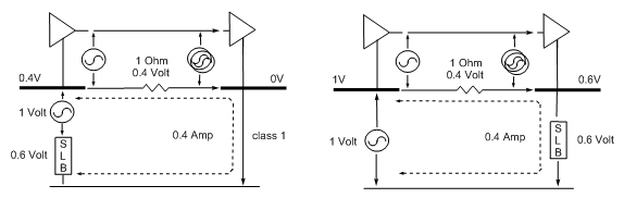
Figure 4.8-5
Figure 4.8-5, We need to think in terms of voltages here. The Safety Loop Breaker circuit drops 0.6 Volts of the 1 Volt noise voltage, leaving 0.4 Volts to be dropped across the impedance in the circuit – the interconnect shield. In the left hand circuit, the Safety Loop Breaker circuit is under the noise source so the Safety Loop Breaker circuit drops 0.6 Volts, leaving 0.4 Volts on the signal reference. The other signal reference is at 0 Volts (ground). In the right hand circuit, the Safety Loop Breaker circuit is in the attaching component so that the signal reference has the 0.6 Volts of noise that is dropped by the circuit. The other signal reference has 1 Volt of noise on it. In both cases there is 0.4 Volts between the signal references but the left hand circuit has a much lower ground noise.
What would happen if we installed a Safety Loop Breaker circuit in both the component with the noise as well as the attaching component?
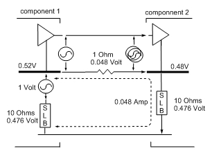
Figure 4.8-6
Figure 4.8-6, Here is an example of there being not enough voltage around the loop for the Safety Loop Breaker circuits to drop 0.6 Volts each. The voltages and current are now established by the impedances in the loop. The noise on the interconnect shield between the two components has been reduced by almost a factor of ten and the noise on the ground system, 0.48 Volts on the right and 0.52 Volts on the left, is about half-way between the two cases shown above that each have a single Safety Loop Breaker circuit.
These examples with a single noise source and only two components are pretty simple. More complex cases with multiple components, multiple noise sources and isolated Safety Loop Breaker circuits are shown below.
Multiple Ground Loops
Now, strange things happen when we add additional components to the system. This is where we see the effect of ground noise in the system.
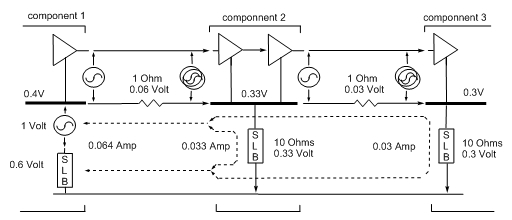
Figure 4.8-7
Figure 4.8-7, A third component with a Safety Loop Breaker circuit added to the system. This example is an extension of that shown above in figure 4.8-6. Component 1 and component 2 are exactly the same with 1 Volt of noise being generated in component 1. The difference is that a third component, exactly the same as component 2 is added to the system. The Safety Loop Breaker circuits in components 2 and 3 are in parallel, effectively lowering the impedance in the loop that is presented to the noise generator in component 1. The result is poorer noise reduction. Not only has the noise on the shield of the interconnect cable between components 1 and 2 increased, but the noise on the signal reference of component 2 is passed along on the shield of the interconnect cable to component 3. Note that the total noise impacting the signal across the system is the sum of the noise between components 1 and 2 plus the noise between components 2 and 3. So the total noise is 0.09 Volts (0.06 + 0.03) – almost twice the amount present without component 3. Because this noise is on the ground system, it is always present everywhere in the system even if a different signal is selected to be active (for example in a preamp). Okay, so what would happen if the added device were a class 1 device with the reference directly connected to the safety ground?
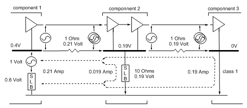
Figure 4.8-8
Figure 4.8-8, A third component, which is a class 1 device, attached to the system. This example is the same as that in figure 4.8-7 except that component 3 is a class 1 device. The noise performance in every area is worse than if component 3 had a Safety Loop Breaker circuit. This is because the class 1 device effectively nullifies the Safety Loop Breaker circuit in component 2. Now, an interesting thing happens if we swap component 2 with component 3. The components are the same, just their position has changed.
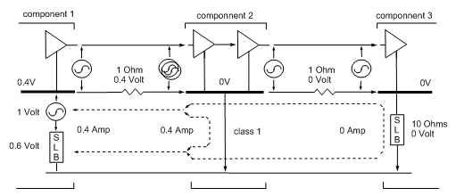
Figure 4.8-9
Figure 4.8-9, The noise on the shield of the interconnect cable between components 1 and 2 is about twice that as in the case shown in figure 4.8-8 but the total noise as seen by component 3 is about the same (0.4 Volt + 0 Volt versus 0.21 Volt + 0.19 Volt.) The important difference is that now the ground system is clean. Note that the Safety Loop breaker circuit in component 3 is redundant and it doesn’t make any difference if it is there or not. We are back to where we were in figure 4.8-5.
The conclusion from the above is that adding a second Safety Loop Breaker circuit in the attaching component can help the noise on an individual interface, but at the expense of noise on the ground system. Adding additional Safety Loop Breakers circuits to the system may actually be detrimental. Including a class 1 device in the system provides a clean ground system at the expense of increasing the noise on the individual interface.
Multiple Noise Sources
Let’s now take a look at what happens when there is multiple noise sources in the system.
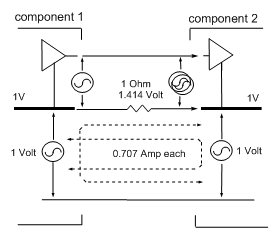
Figure 4.8-10
Figure 4.8-10, Two interconnected noise sources. Because the two noise sources are similar but not identical, the noise voltages will sometimes add and sometimes subtract. The power of the two noise signals will directly add, while the voltages will add as the square root of the sum of the squares of the two noise voltages. The result is that each noise source contributes 0.7 Amp of noise current and the combined effect produces 1.414 Volts of noise across the 1 Ohm resistor.
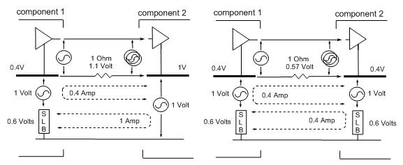
Figure 4.8-11
Figure 4.8-11, Nothing unusual here; one Safety Loop Breaker circuit helps a little and two circuits help a lot more. As with a single noise source, things get interesting as we add additional components to the system.
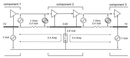
Figure 4.8-12
Figure 4.8-12, A single Safety Loop Breaker circuit with two noise sources. This example, as well as the following example shown in figure 4.8-13, is the same as two circuits shown in figure 4.8-5 back-to-back. In this example both components 1 and 3 have 1 Volt noise sources and component 2 has a Safety Loop Breaker circuit inserted into both ground loops. The diodes in this circuit clamp the voltage across it to 0.6 Volts; therefore each cable shield has 0.4 Volts of noise. Note that the two noise voltages do not add in this case because the total voltage is limited to 0.6 Volts.
What if the Safety Loop Breaker circuits were in the components with the noise rather than in the attaching component?
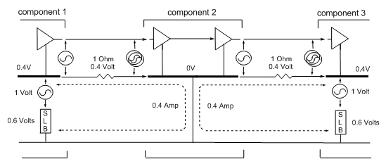
Figure 4.8-13
Figure 4.8-13, Safety Loop Breaker circuits in the noisy components. The difference between this example and the previous is that component 2 is now a class 1 component with its signal references connected to safety ground. The signal references of components 1 and 3 are 0.4 Volts away from this ground. Thus, the ground system in this example is a lot quieter than that of figure 4.8-12. This is most important if component 2 were a preamplifier with other components attached. The noise on the ground system is seen by and thus affects all components in the system.
Okay, but what if component 2 also had a Safety Loop Breaker circuit; wouldn’t that be even better?
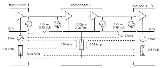
Figure 4.8-14
Figure 4.8-14, An example of the interaction of three Safety Loop Breaker circuits. The analysis of this gets messy because the two noise sources interact through all three of the Safety Loop Breaker circuits. The result is that you trade off a little noise on the interfaces for a lot more noise on the ground system.
You can add or remove Safety Loop Breaker circuits at different points in the system but the problem is that both noise sources contribute to each other through shared impedances and need to be isolated from each other so that there are no shared impedances.
The conclusion from the above is pretty much the same as with a single noise source: Adding a Safety Loop Breaker circuit in the attaching component in addition to that in the noisy component can help the noise on an individual interface, but at the expense of noise on the ground system. Including a class 1 device in the system provides a clean ground system at the expense of increasing the noise on the individual interface.
Okay then, would it help to put a separate Safety Loop Breaker circuit on each interface?
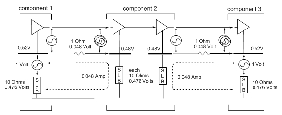
Figure 4.8-15
Figure 4.8-15, Separate Safety Loop Breaker circuits. At first glance this looks pretty good – each cable shield has only 0.05 Volts of noise just like the circuit in figure 4.8-6. However there is a problem lurking internally in component 2 that will become obvious if we re-draw that portion of the circuit.
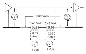
Figure 4.8-16
Figure 4.8-16, Internal ground structure of component 2. We see that although the noise voltage on each signal reference is pretty good, that we have 0.68 Volts (0.48 Volts x 1.414 noise addition factor) of noise between the two signal references. This is far worse than with a single Safety Loop Breaker circuit and is almost the same as with no Safety Loop Breaker circuit at all! By the way, this example shows what the result can be when violating Grounding Rule 4 – the signal references must both be connected to the system star ground. Okay, let’s just connect the two signal references together – that should fix the problem. Nope – what we now have is the same as the circuit in figure 4.8-14 except that the two 10 Ohm impedances are now in parallel making 5 Ohms. This reduces the effectiveness of the Safety Loop Breaker circuit such that the combined noise voltage on the references is now 0.51 Volts and the noise voltage across each interconnect shield impedance is 0.28 Volts – just about the amount of a single Safety Loop Breaker circuit.
Thus the conclusion is that you can do no better than with a single Safety Loop Breaker circuit in a component.
The conclusions about a Safety Loop Breaker circuit are:
- The circuit does not eliminate, or even reduce, noise – it moves the noise. The noise may be moved to a place where it does not affect the signal. However, the noise may be moved to a place where it does affect the signal; where the noise is moved depends on where the circuit is located.
- A circuit located in a device causing the noise always helps.
- In a system containing only two components, the device causing the noise and the attaching device, adding a circuit to the attaching device also helps.
- In a system containing more than two components, adding a circuit to the attaching device hurts the noise performance. This is because some of the noise is moved to the ground system.
- It hurts the noise performance to have more than one circuit in a device. This is because the noise will be moved to the internal signal reference in that device.
- Thus the conclusion is that the Safety Loop Breaker circuit helps reduce the noise by inhibiting the noise current in a ground loop; however it does not eliminate the problem as would galvanic isolation or fixing the ground loop problem. None of the noise is eliminated – it is just moved to a part of the circuit where it will have less of an impact on signal.
4.9 - Construction Summary
- Follow the grounding rules in section 4.1.
- Make a ground map and carefully design the ground structure using stars and busses.
- Power supplies are two-terminal devices. Do not tap into the internal circuitry.
- Use Safety Loop Breaker circuits only where they are needed.
Chapter 5 - Conclusions
Audio Component Grounding
Most grounding problems are caused by something being connected to the wrong ground or ground current flowing where it is not needed. “Wrong ground” implies that there is more than one kind of ground and I differentiate grounds as follows:
- Safety ground – this is the separate (green or green/yellow) wire in the power line going back to the circuit breaker panel. It is connected to earth at the panel.
- Chassis and cable shields – These provide protection from electrostatic fields.
- Power common – This is the 0 Volt reference from the power supply.
- Signal reference – This provides a point of reference for the signal in a circuit.
These grounds need to be connected together in a very specific manner as part of the design of a component grounding structure. Grounding should be designed as carefully as any other part of the component and I encourage you to make a map of the grounding structure to show up any potential problems. Here are some rules to help you plan your grounding structure.
Rule 1: Each of the following must be connected to the system star ground by one and only one route.
- All signal references
- All power commons
- Shields of non-galvanically isolated single-ended inputs and outputs
- Safety ground and chassis. The safety ground and chassis should be thought of as a single entity.
- The connection may be direct, or indirect through a star-of-stars or buss. This is expanded upon below.
- The safety ground and chassis may be connected to the system star ground through a Safety Loop Breaker Circuit.
- The “one and only one” part of this rule precludes ground loops. There is no excuse for a ground loop within a single component.
Rule 2: The shield of a balanced input or output (XLR pin 1) must be connected to the chassis at or as close as is possible to the connector.
Rule 3: The shield of a single-ended input or output that is not galvanically isolated must be directly connected to the system star ground.
The shield is the signal reference in the cable
Rule 4: Any circuit associated with an input or output that is not galvanically isolated must have its signal reference directly connected to the system star ground.
Rule 5: The mains safety ground must be directly connected to the chassis.
From
IEC 60950, “The wire is terminated with a closed loop connector which is fixed to the earthing stud or screw with a star or lock washer and a nut. Other parts of the product that need to be earthed are connected by closed loop connectors to the same stud and locked with an additional nut. It is important that the earth wire from the power supply cord is located at the bottom of the stud and locked with its own nut. The earthing stud must not be used for any purpose other than earthing. It cannot be used, for example, for the mechanical fixing of parts other than the earth conductors. Its mechanical structure must also be such that it cannot be loosened from outside the device. For example, it cannot be a post fixed with a screw from outside the product.”
Rule 6: Each signal reference must be directly connected to its power reference.
That is, no circuit may have its signal reference connected to its power common
through another circuit’s signal reference or power common. This rule allows for a star-of-stars with the signal reference and power common directly connected together in a star and that star connected to the system star (either directly or through a buss).
Rule 7: Circuits may be grouped together with their signal references forming a buss.
The order of the grouping is not arbitrary. Just as the signal is routed along, stage to stage, the associated signal reference can be routed with the signal between stages. Keep the signal and its associated signal reference electrically close together; they should be treated as a pair. This minimizes the risk of noise being injected into the signal reference.
One end of the buss should be connected to the system star ground, either directly or by a star of stars.
Audio Component Interconnection
- Provide a dedicated branch power line, or at least a benevolently loaded one, for audio components.
- Plug all audio components into the same power strip or power outlet.
- Provide a separate branch power line for computers, TVs or any other devices having switching power supplies.
- Provide isolated interfaces for connections between:
a. The audio system and other devices, like computers or TVs.
b. Pin 1 Problem devices and any other audio component.
c. Class 1 component and a class 2 component. Isolation may not be needed for this case.
d. Class 1 component and an SLB isolated component. Isolation may not be needed for this case.
- Loops aren’t bad – it depends on what is on the loop.
- Use shielded heavy gauge twisted pair interconnect cables.
Understanding, Finding, & Eliminating Ground Loops in Audio & Video Systems by Bill Whitlock has a lot of great information on solving interconnection problems in audio systems.
Bibliography and References
Books
[1] Grounding and Shielding Techniques in Instrumentation, Ralph Morrison.
This book is complete and explicit with lots of examples. It is very technical and not a casual read but is essential to thoroughly understand the subject. It is now in its 5th edition and is expensive, although earlier editions are available used. Page references in this article are from the 3rd edition.
[2] Solving Interference Problems in Electronics, Ralph Morrison.
Page references in this article are from the 1st edition.
[3] Noise Reduction Techniques in Electronic Systems, Henry W. Ott.
Like Morrison, this book is an excellent reference for the subject material. Page references in this article are from the 1st edition.
[4] Electromagnetic Compatibility Engineering, Henry W. Ott
A significant update and expansion of [3] Get this book even if you have his earlier one.
[5] through [10] Reserved for future entries
Publications
[11] Journal of the Audio Engineering Society, Volume 43, Number 6, June 1995. This whole issue is on shields and grounds.
[12] Susceptibility in Analog and Digital Signal Processing Systems, Neil A. Muncy JAES, Volume 43, Number 6, June 1995 Pages 435-453. Muncy introduced the “Pin 1 Problem” in this paper
[13] Balanced Lines in Audio Systems: Fact, Fiction, and Transformers, Bill Whitlock. JAES, Volume 43, Number 6, June 1995 Pages 454-464.
[14] AES48-2005 AES standard on interconnections – Grounding and EMC practices – Shields of connectors in audio equipment containing active circuitry.
[15] Electro-magnetic compatibility – “The art of grounding” , Brent Hertz
AES preprint 3041 (G-1) February, 1991. Grounding in the studio environment.
[16] EN 60065 - Audio, Video and Similar Electronic Apparatus, Safety Requirements
[17] through [20] - Reserved for future entries
Articles on the Internet
- Interconnection of Balanced and Unbalanced Equipment Bill Whitlock
- Hum & Buzz in Unbalanced Interconnect Systems, Jensen AN-004, Bill Whitlock
- A New Balanced Audio Input Circuit for Maximum Common-Mode Rejection in Real World Environments Bill Whitlock
- Understanding, Finding, & Eliminating Ground Loops in Audio & Video Systems Bill Whitlock
- Subtleties Count in Wide-Dynamic-Range Analog Interfaces Bill Whitlock
- Sound System Interconnection, Rane Corp. Technical Staff
- Grounding and Shielding Audio Devices, RaneNote 151, Stephen Macatee
- Considerations in Grounding and Shielding Computer-Controlled Audio Devices, Stephen Macatee
- Pin 1 Revisited, Jim Brown
- SCIN: Shield Current Induced Noise, Jim Brown
- A Ham’s Guide to RFI, Ferrites, Baluns, and Audio Interfacing, Jim Brown. A different perspective on the problem. A particularly good coverage of filtering RFI.
- Power and Grounding for Audio and Video Systems: A White Paper for the Real World – International Version, Jim Brown. An excellent introduction to the subject, from the professional audio perspective, but a lot applicable for the advanced hobbyist.
- Ground Loops, D. Self. Ground loops – how they work and how to deal with them.
- Star Grounding, Randall Aiken
- Common Mode Choke Theory
- The Two-Point Earth Method. Inside the Sakuma Amplifier.
- Earthing Your Hi-Fi – Tricks and Techniques, Rod Elliott. A good description of the Safety Loop Breaker Circuit.
- Blocking Mains DC Offset, Rod Elliott
- Earthing. Short introduction to the requirements for a Class 1 device.
- Ground Loop Problems and How To Get Rid of Them, Tomi Engdahl
- Ground and (safety) Earth, Eric Juaneda. Good coverage of parasitic currents.
- International Safety Standard for Information Technology Equipment, IEC 60950
- When good grounds turn bad – isolate! Thomas Kugelstadt. Analog Applications Journal, 3Q 2008, page 11.
- So You Thought Your Amplifier Was Balanced? Andy Grove and Peter Qvortrup. Good introduction to the advantages to balanced circuitry, and particularly transformer interfaces.
Revision History
- May 29, 2009 - 1.0
Base
- June 1, 2009 - 1.1
Expanded on computer attachment In Effective Interconnection Schemes.
- June 13, 2009 - 1.2
Re-structured the Effective Interconnection Schemes section.
- June 29, 2009 - 1.3
Minor editorial changes
Added Conclusions chapter
- July 3, 2009 - 1.4
Changed Input Switching section.
- July 9, 2009 - 1.5
Added section on Safety Loop Breaker circuit
- July 20, 2009 - 1.6
Restructure chapter 3 for better readability
- July 30, 2009 - 1.7
Add reference to t.i. Analog Applications Journal.
- September 7, 2009 - 1.8
Correct typo
- April 23, 2010 - 1.9
Restructure chapter 3 to eliminate duplicate heading number
- May 1, 2010 - 1.10
General cleanup
fix typographical errors
fix several figures
update references
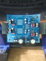
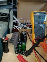


 Edited by moderation to remove reported image


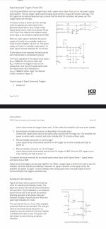
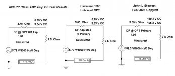
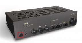

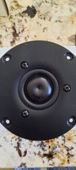


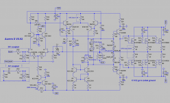
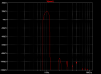
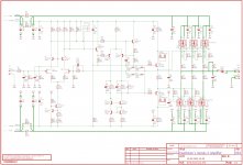


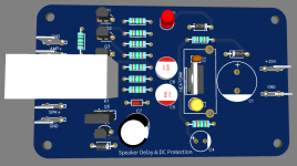
 ...
...