Amplifier power into tweeters in active setup

This is probably going to sound like a newbie question but I can’t find the answers searching the web

If you are running a active setup with tweeters that have a rating of say 120w
And you have power amps rated at say 200w

Is there any danger in damaging the tweeter in the real world or is this safe to do ?

If no is it more sensible of using a amplifier of the max rating of the speaker

Noob needs help (please) with Electro-voice crossover

Hey there. I just purchased two Electra voice S 15 PA speakers. One of the speakers, has a crossover that’s not working. Both the horn and the speaker are good, but when connected to the crossover, only the woofer is getting signal. Here are some photos of the crossover. Any suggestions as to where I should begin to troubleshoot. I only have a multimeter. Any help would be greatly appreciated. Much thanks!

Attachments

  • 90FD7F8B-E5EA-415A-8B53-90331EB5FBEA.jpeg
    90FD7F8B-E5EA-415A-8B53-90331EB5FBEA.jpeg
    309.5 KB · Views: 124
  • A0D1B7D0-8C01-4115-8B6B-378A3B41DC7A.jpeg
    A0D1B7D0-8C01-4115-8B6B-378A3B41DC7A.jpeg
    296.2 KB · Views: 105
  • 601AD9BE-68C8-456E-BD95-390555BC3A35.jpeg
    601AD9BE-68C8-456E-BD95-390555BC3A35.jpeg
    283.6 KB · Views: 108
  • 543FF85C-D8E0-4DB8-A14D-A9E134F1B927.jpeg
    543FF85C-D8E0-4DB8-A14D-A9E134F1B927.jpeg
    322 KB · Views: 113
  • AA98F78A-9845-417C-BEAB-100F7E082532.jpeg
    AA98F78A-9845-417C-BEAB-100F7E082532.jpeg
    254.3 KB · Views: 112
  • 6678381F-00DE-437E-9E2E-751133ABE30B.jpeg
    6678381F-00DE-437E-9E2E-751133ABE30B.jpeg
    364.6 KB · Views: 113

Crown Macro Reference amp info

I picked up a Crown Macro Reference amp and the right channel was in protection. I put all new outputs and drivers in it and cleaned everything up and it now works as advertised..... SORT OF..... The power meters work fine but the Logo/Lighting on the front panel is out and I thought the switch just needed to be switched but after taking off the outer face and flipping the switch, it still doesn't work. The switch is fine and all the connectors are connected but that's as far as I can go without having a schematic to follow. By any chance does anybody HAVE or KNOW where i can find a copy of the power supply schematic?

Orion Died, Hoping someone can help in guiding to some repair tips.

Good evening,
I have a Orion XTR1400.1D.
It was in use for maybe a year. I bought it new but not in the box or at least told it was new.
The batteries on my truck died and I assume they killed the amp when it was boosted.
I have been reading as much as possible to figure out what to test.
It’s very obvious that the transistors blew up. Smoke/smell/burn marks. I had no output but the amp had the light on but not the protection light. No fuses blew it has 4 30 amp fuses on the amp.
I attempted to replace and they simply blew up again.
I am going to order more but would like to not run in circles replacing random parts. It’s obvious they were defective.
I have another amp that functioned torn apart to replace one of the potentiometers on it and am trying to use it to compare readings.
I think I have a dead short in the amp somewhere as I have continuity between positive and negative terminals and my other test amp is not like this.
None of the capacitors are swollen. I have tried checking the transformer for shorts and can’t seem to find anything wrong.
I have a soldering iron, soldering pump, I just ordered an oscilloscope should be in the next couple days.
I have a multimeter as well.
I’ll post a picture of the blown up internals tomorrow when I get a second.
I would appreciate any help

VTVM frequency-dependent drift

I am troubleshooting the frequency-dependent measurement drift on my newly acquired CTR HRV-260 VTVM in the audio range.
VTVM is connected to DAC which outputs 20Hz-20kHz sweep at 245mV (-10dBVU) and 775mV (0dB). I can confirm that output is linear with another instrument. On 0.1V and 1V ranges, the measurement is accurate and the needle is steady across the frequency range. However, switching the VTVM to 3V range or higher, the same signal will not be measured correctly, by a few dB. Moreover, as the sweep frequency goes up, so will the needle, by 5-6dB. This does not happen on measurement ranges below 3V.

The device was cleaned and calibrated. I am attaching the schematic and kindly ask for advice where to look for a fault. Thank you in advance.

Attachments

44 years ago, March 1979, Philips introduced the Compact Disc System to the world

'On March 8, 1979, Philips, the Dutch consumer electronics company, unveiled a revolutionary new medium that would forever change the way we listen to music. The event took place in Eindhoven and was attended by press representatives from across Europe.'

https://www.dutchaudioclassics.nl/4...roduced-the-Compact-Disc-System-to-the-world/

I was born in 1974 and didn't experience the development of the compact disc system (though as a 10-year-old kid I was marveling at Philips' magnificent CD880 and CD960 CD players), but what an exiting period this must have been. All your LPs that you had to replace for those clinical silver discs. 😉

Are there people here who lived through the introduction? What did you guys think of the new system? Did you welcome it with open arms or were you skeptical?

B&C DE5 on JBL2404 horns

I own a pair of salvaged JBL2404 horns (baby butt cheeks) wihout drivers.
The only driver I could find that would fit the 1/2" throat of those horns and with a high end frequency response and sensitivity that would somewhat resemble that of the original drivers, is the B&C DE5.
Do you think this could be a match that would be worth trying ?
The power handing of the DE5 would not be a problem as they are meant as supertweeters on a high efficiency home speaker system.

https://www.bcspeakers.com/en/products/hf-driver/0-5/8/de5
https://jblpro.com/en/site_elements/2404h-information

More info on the B&C DE5
https://www.diyaudio.com/community/threads/b-c-de5-or-de7-exit-angles.251207/

Orchard Audio’s New PecanPi®+ DAC and Streamer Feature AKM’s Latest Flagship Chips

Orchard Audio introduces the PecanPi+ DAC and PecanPi+ Streamer, further expanding the highly reviewed line of PecanPi® products. The PecanPi+ DAC leverages Asahi Kasei Microdevices’ (AKM) latest flagship AK4499EXEQ digital-to-analog converter (DAC), and AK9141EQ ΔΣ modulator chips. The 4499 utilizes the latest multi-bit switched resistor DAC method, employing VELVETSOUND™ technology.

AKM’s design separates the digital processing and the digital-to-analog conversion into separate devices, minimizing the effects of digital noise within the analog output and resulting in a noticeable improvement in both sound quality and signal to noise ratio. The PecanPi+ design fully explores the benefits of the latest technological advancement in audio reproduction, providing pure, unaltered audio that wholly reproduces the source material. The AKM chips are coupled with extremely low noise power supplies, an ultra-low jitter clock, and the latest high-performance audio operational amplifiers from Burr-Brown (Texas Instruments). This enables the PecanPi+ DAC to achieve staggering performance.

The PecanPi+ Streamer is a plug-and-play high-resolution music streamer. Control music wirelessly using your phone, tablet, or computer. The device can also be connected to any digital transport utilizing S/PDIF. The PecanPi+ DAC is ideal for do-it-yourself (DIY) enthusiasts.

Preorder pricing is available thought the end of March.

Specifications: PecanPi vs. PecanPi+

SpecificationPecanPiPecanPi+
Signal-to-Noise Ratio: XLR output (A-wt)130dB133dB
Signal-to-Noise Ratio: RCA output (A-wt)124dB128dB
Dynamic Range: XLR output125dB129dB
Dynamic Range: RCA output122dB124dB
SINAD: XLR output110dB116dB
SINAD: RCA output110dB112dB
Bit/Sample RatesUp to 24-bit / 192KhzUp to 32-bit / 384kHz

Here are some test results comparing the PecanPi vs the PecanPi+. Note that I had to borrow and APX555 because the 525 that I have is not capable of measuring the performance of the new PecanPi+ DAC. I think that alone says a lot.
THD+N Ratio vs Freq (XLR) -- PecanPi (Blue) -- PecanPi+ (Red).jpg

THD+N Ratio vs Measured Level (XLR) -- PecanPi (Blue) -- PecanPi+ (Red).JPG


These measurements are for the PecanPi+ only.
Jitter Spectrum and Noise 256k FFT, 16 Averages (XLR).JPG

Multitone FFT Spectrum (XLR).jpg


Many other specs and test results are available on my website https://www.orchardaudio.com.

Eye Candy...

PP+_Top_1920.jpg

PP+_Back_1920.jpg

Wire Silver plated copper

SOLD! Large batch of silver-plated copper wire. 20, 22, 24 and 26 gauge. Variable lengths, but most are 10'.
Also included are shielded and 2 wire lengths. 12-gauge silver plated speaker wire included in the batch. (For internal wiring.)
Most obtained from Navships. This is a very large batch of wire!
$35.00 shipped. US and Paypal only.

Attachments

  • Wire.JPG
    Wire.JPG
    116.8 KB · Views: 102

Haruna cabinet build questions

I'm planning to build a pair of Scott Lindgren's Haruna speakers from frugal-horn.com, already have the FE166En but have a few questions, if anyone can advise.

1) The biggest problem is that I'm in Azerbaijan and have discovered that birch ply only seems to be available in 1.5m square sheets, whereas Haruna is 1.85m tall.

I suspect that issue is going to force me to use MDF. But I wonder if it might be a worthwhile "compensation" to increase the side panels from 19mm to 25mm thick? They will be quite a bit heavier but that's only really a problem during the build.

We do have businesses here that cut MDF to size, so that might actually make the project much easier - it can also come with various finishes, but then I couldn't use a nail gun to fix the internals in place, which is what I did with my Dallas 2. Though I could also veneer the outside afterwards.

2) The instruction says "you may replace the stacked corner deflectors with a single angled piece". If I used an angled piece I would then create a hole that needed to be filled with sand etc. so that actually seems to be a disadvantage. But is there any technical preference one way or the other of a step vs. a smooth surface?

3) The default damping is "line 5 faces of the driver chamber with 1/2" material...ensuring the throat remains clear" - so this seems to mean that the 6th side, with no damping, is the back side of the baffle?

4) In my Dallas 2s I lined the driver chamber with 3mm felt, using a spray glue, but it made a helluva mess as it was difficult to spray accurately. Maybe a liquid glue would have been better, but I was wondering if an alternative way would be to glue velcro in the driver chamber and use cut-to-size pieces of 12mm wool felt so that the damping was removable. This approach would also perhaps let me experiment with different materials in the future. Or is it important that the lining is hard-fixed to the cabinet over all its surface?

5) I've seen a couple of threads where the builders have added a supertweeter here and here, though they both seem to be using a Fostex FE168E Sigma. Is this something that I need to be considering for a standard FE166En? One puts the supertweeter inside the cabinet above the main driver, one hangs it off the side.

6) Last one for now, any thoughts as to whether an ACA Mini will work OK with these? I don't listen extremely load, but do plan to put these in a large listening room.

Thanks!

2023 Econowave?

I need new speakers, and really want to build something. I've been looking around and fell in love with the Mezzo Calpamos. It's beautiful, a little different, and seems like it would excel at HT and music. It's a little big (but in some dimensions smaller than my magnepan mmg) but I think I might be able to talk the wife into it. Then, I realized I was looking at the price for one kit, and needing two I'm pretty sure it's out of budget.

I did more looking around and came across the Econowave and all it's iterations and thought I might be able to DIY a higher end econowave that is close for a lot less $$. However:

1. Most of the parts (especially waveguides) seem to be discontinued

2. Nobody seems to make them anymore. I don't know if that is because of question 1, or because something better came along, or if they weren't that good to begin with.

3. I wonder if econowaves "replaced" by designed that place normal tweeters in a waveguide that combined the best of both worlds?

Any thoughts? Thanks!

Run power tubes at max voltage?

This is a question of general interest to those designing or modifying amplifiers, not just this one kit.

Is anyone but me concerned about running the 6P14 (or EL84) output tubes at ~350 volts in this amplifier? Isn't this voltage going to eat up the tubes very quickly? I don't want that. Schematic with suggested voltages from the building directions is attached.

The kit comes with what is labeled a "spare" zener diode that is 91 volts per the label instead of 100 volts like the others. That's in there to reduce the regulated screen voltage by 9 volts I assume? I am getting 316V on the regulated screen output when spec is 290V-305V.

Edit: I am well aware of the option of using a bucking transformer, and I am not interested in that solution for several reasons. As with most Chinese amplifiers, it is designed for 110VAC not the 121VAC that I have at my wall outlet.

Update: installing the 91V zener diode to replace one of the 100V zener diodes produced a perfect 297V on the regulated screen voltage.


6P14 tube - translated from actual Chinese specs (EL84 is similar):

Performance Parameters
Filament voltage (Uf)=6.3V
Filament current (If)=0.76A
Anode voltage (Ua) =256V
Anode current (Ia) = 48±8mA
Second gate voltage (Ug2) = 256V
Second gate current (Ig2) ≤7mA
Transconductance (S) ≥9mA/V

Limit Application Data
Maximum filament voltage (UFMax) =7V
Minimum filament voltage (Ufmin) =5.7V
Maximum anode voltage (Uamax) =300V
Maximum second gate voltage (Ug2max) = 300V
Maximum filament and cathode voltage (Ufkmax) ±100V
Maximum anode dissipation power (Pamax) = 12W
Maximum second pole dissipated power (Pg2max) = 2W
Maximum cathode current (Ikmax) = 65mA
Maximum first gate resistance (Rg1max) = 1Mohm

Attachments

  • amplifier schematic wo magic eye.jpg
    amplifier schematic wo magic eye.jpg
    252.2 KB · Views: 106

How to measure the required power for each driver? At 1 khz is correct? 2W D class is enought?

My mesuarament is correct? Example. At 1khz, 8 Ohm rezistor voltage is 50mV-150mV for normal too high volume. This means requared power is 0,15/8= 0,01875A. 0,01875*0,15=0,0028125w. Is this real? What i'am doing wrong? Driver ir FaitalPro 6rs140. This means enought power for one driver i some 1W? Can i use D class amplifier 2 x 2W? This is for active connection in 3way system. For each channel 2w enought? Watching at D class PAM8803 chip. Drivers is 10rs350, 6rs140, SB26STCN.
Link to system https://www.diyaudio.com/community/...italpro-6rs140-10rs350-need-some-help.393606/
1678266217235.jpg

DSC07144resize.jpg

  • Article Article
The DAC stops here: The Ayre QB-9 Twenty

Well, that was expensive. Sounds like it's gonna be worth it though.

DSC_4064s.jpg


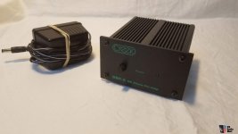
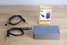
The Ayre QB-9 Twenty is the latest of several upgrades made to this series over the years. New faceplate, new circuit, updated DAC chip. $3500 US retail.

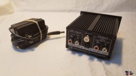
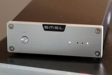
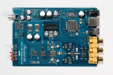
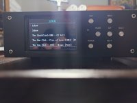
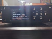
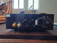
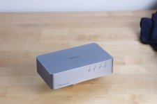
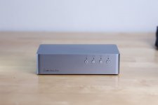
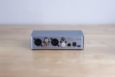
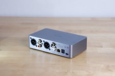
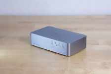
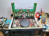
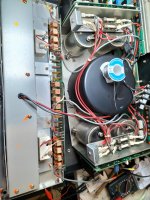
The faceplate is very handsome in person by the way. It's aluminum, and from what I can guess the text and logo are left in polished mirror finish with the surrounding metal etched away to a matte grey. At back, there is a USB Type A input together with RCA and XLR line outputs, and jack for the AC power cable - no external power supply to fuss over! Apart from a set of dip switches in the back, there are no physical controls. The unit engages to display the sampling rate when the USB is connected to a computer and some audio software is run. The details of the sampling rate, etc., are set from the computer.

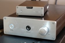
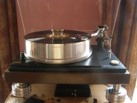
In terms of standard rack chassis sizes, it's roughly half width and a nominal height - compact but not tiny, it fits comfortably next to the Teac HA-501 shown in the photo above.

I appreciate that this DAC costs an order of magnitude more than what most people on this forum would likely consider paying for this functionality. It would be nice if it was possible to get this level of performance for $350, but in my experience, this is not possible. The QB-9/20 [as I will call it from here on in] is better than the Chord 2Qute (which is thin and sharp in comparison) and - while sharing some family characteristics - better than the Ayre Codex too (which is generally rougher). I can't comment on how it compares to similarly priced alternatives, nor could I even point to any. I didn't shop around, I just impulse-bought a used unit from a Japanese auction site. I heard enough to like in the Codex and had read the overwhelmingly positive reviews for the QB-9 series.

The first impression, listening via the HA-501 and Sennheiser HD600s, is of a) a low noise floor, b) a wide and detailed soundstage, and, c) an overly polite top end. Coming from the 2Qute, which has a lot of top-end sizzle, let's just say it took me a little while to re-adjust this new normal. By the second or third listening, though, I was satisfied that the Ayre wasn't playing the "rolled off treble = hi-fi" trick, it just wasn't adding splash, grit, or shine.

Where it gets interesting is that, after assuming the politeness was partly due to the warm balance of the headphone amp, I switched back to the Sapphire. Despite the anticipation that this would be the match made in heaven, I was disappointed to hear that the Sapphire brought a little metallic hardness to the treble, and added nothing much in the way of positives vs. the Teac. A little more experimentation revealed that the single-ended output from the QB-9/20 doesn't bring the same magic as the balanced XLR. The Teac, when connected via RCA, also sounded a little lackluster. Not bad by any measure, just - compared to what I had just experienced through the XLR cables - normal. That made the choice very simple: QB-9/20 / XLR / HA-501 / HD600. Together, this combo absolutely kills it.

  • Article Article
Commentary on the audiosciencereview of the Ayre Codex DAC/Headphone amplifier

A review of the Ayre Codex by Audiosciencereview

I bought an Ayre Codex for myself last year to find out how my own diy efforts, the Sapphire headphone amplifier, would compare to a serious high end product from a serious high end company. I had read the audiosciencereview report above before I decided to buy it, as well as many other online reviews. It did not dissuade me because I had faith in Ayre and their design philosophy. This is only reasonable: the Sapphire shares much of the same design principles of the Codex, and I know from experience that the measurements we make to test audio equipment rarely correlate with perceived sound quality. That the Codex posted some disturbing test scores did not bother me. Put it another way, I've had plenty of gear pass through here that won great praise for measurements but sounded like cr*p...

In the next few posts I'll be providing some annotations to the Codex review based on my own listening experiences, cross-referenced with my thoughts about how the Sapphire sounds in comparison. Expect some soapboxing about Ayre and the commercial hifi industry in general, together with come color commentary on the measurements-vs-listening-tests debate.

Stay tuned!
  • Like
Reactions: A Jedi

  • Article Article
Another day, another DAC: S.M.S.L. Sanskrit 6th mini-review and commentary

I decided to give the S.M.S.L. Sanskrit 6th a whirl recently to see how things stood on the cheap USB DAC front.
S.M.S.L. has long held my respect for trying hard to deliver high-quality audio at an extremely fair price. Just a quick look over the DAC's circuit board tells you that these are people who care about their work - from the etched S.M.S.L logo to the clean, logical parts layout. The build quality is apparent too in the simple, nicely finished case, which matches my Sapphire headphone amp (shown below) in "mini-me" style.

Part 1.

It's all "there", from the Cirrus Logic WM8740 DAC and NJM2114 opamp output with what looks like discrete transistor pair output buffers. The board generates 3.3 V, 5 V, and +/-12 V rails from the 9 V DC input. Other components include a 7805 voltage regulator, cmedia CS6631A USB audio processor, and Onsemi LC89091 receiver. A lot of stuff for the price. So it's a frustrating disappointment to have to report that it doesn't sound as good as I hoped. The sound is smooth, clean, and nicely detailed however. So, for the price, here again, one can't complain: it does what one might reasonably ask of it. It's hard to put one's finger on the source but musically, it fails to rise to the occasion. The sound is weak, feathery, light. Complex passages dissolve into incoherence. There is no power reserve. Perhaps due to the switching power supply whatever charge pump circuits are used to regenerate the internal voltage rails. Perhaps distortion from the transistor output stage, or insufficient filter capacitance near the op amp. These are just educated guesses on my part, but it does raise an interesting point: what does a DAC need to get truly high-end sound?

In Part 2. (coming soon), we'll take a look at exactly that.

Attachments

  • IMBP7077s.jpg
    IMBP7077s.jpg
    215.3 KB · Views: 618
  • IMBP7078s.jpg
    IMBP7078s.jpg
    217.9 KB · Views: 535
  • IMBP7082s.jpg
    IMBP7082s.jpg
    438.6 KB · Views: 746

Power Amplifier PCB Sanity Check

Hi everyone,

I'm redesigning a 5w LM1875 Guitar Power Amplifier that's powered by a Line 6 Helix (Line Level out) as the preamp. Is someone able to have a look over these images and let me know if there are any glaring errors they can see in either the PCB layout or the Schematics? The PSU board is powered by a LRS-36-100 SMPS.

Ive got a version of it already working, but this has had a few major changes from the first design, so before i send for it to be made,I thought I'd ask around get get a few sets of eyes looking over it.

ps. On the PSU board, I have both Audio and Power ground coming back to the same star grounding point on the pins. If that ok to do or should it be tackled differently?

Thanks!

Attachments

  • Schematics.png
    Schematics.png
    81 KB · Views: 98
  • PSUPCB.png
    PSUPCB.png
    73 KB · Views: 95
  • AMPPCB.png
    AMPPCB.png
    117 KB · Views: 93

Vintage belt drive MR-611 turntable radical upgrade with idler wheel drive.

This is a third stage of upgrade process. I think what pics are able to show the process as well as final result. On the final picture the 7 kilogramm platter consisted of 8 parts has been substituted with solid 12 kilogramm one. And yes, it changed the sound signature substancially.
P1010055.JPG

Attachments

  • P1010188.JPG
    P1010188.JPG
    307.4 KB · Views: 87
  • P1010190 — копия.JPG
    P1010190 — копия.JPG
    175.1 KB · Views: 91
  • P1010190.JPG
    P1010190.JPG
    316.5 KB · Views: 100
  • P1010199.JPG
    P1010199.JPG
    341.5 KB · Views: 89
  • P1010200.JPG
    P1010200.JPG
    325.2 KB · Views: 83
  • P1010201.JPG
    P1010201.JPG
    311.7 KB · Views: 90
  • P1010205.JPG
    P1010205.JPG
    377 KB · Views: 85

Pioneer PD 73: having hard time find the track starting point

Hi,

upon resurrecting a Pioneer PD 73, I've carefully completed the calibration process as described in the Service Manual (see previous post).
I've in order:
  • set Tracking Offset to ~0V
  • set Focus Offset to ~0V
  • set RF Offset to ~100mV
  • set the RF level to ~1.5V
  • set the grating for largest T-Err signal after Null Point
  • adjusted tracking balance after grating
  • adjusted tangential and radial screws for optimal eye-pattern

This setup works perfectly with pristine CDs and CD-Rs but when the CD has scratches, black spots or anything far from a perfect surface, I get issues.
Let me explain:
  • in Test mode, everything is read no skips, no jumps just music despite the surfaces defects
  • in "normal" mode, on certain troubled tracks (those that are affected by defects) the player struggles to find the track start or skips seconds while reading the track.

I've tried to play with Tracking Gain and Focus Gain, but I had no good luck...(yet)

Any suggestion? Could it be that the capacitor around the RF Amp / Servo micro are dried and must be replaced?

Many thanks for any valuable suggestion.

PS... the little PD-7300 (which mounts the same identical optical unit PWY-1011) reads flawlessly even the worst disc.

Class D amplifier audible hiss

Hello,

I've been playing with little PAM8403 amplifier and I have problem with a noise. I have to say I didn't analyze the spectrum in any software but by hearing it I would say it is something close to white noise. It doesn't change at all with turning the volume knob up or down or shorting the inputs. So I started looking on the internet for possible causes.

I found out that it could be the chip itself (PAM8403 doesn't have the best SNR value) but then I found some tests of different cheap boards with the same chip (not the PAM8403) and there were big differences between them in term of audible noise, similiar to what I'm hearing. And since then I wonder:

What causes this audible level of noise and can I get rid of it? It's a broad question, I know, sorry for that. I have two ideas on my mind - It's problem with filtering the power supply rails - or - The chip is causing this and those cheap chinese boards, whose tests I've seen, were using just bad clones of original chip.

I bet it's much more complicated than just this. So thank you very much for any useful informations or materials. I really appreciate it!

Where are the LTSpice models actually located?

I signed up for the io group at https://groups.io/g/LTspice

But when I click on the links for the archives of the models below, the link just reverts back to the page above.
https://groups.io/g/LTspice/files/z_yahoo/all_files_z_yahoo.htm
https://groups.io/g/LTspice/files/z_groups.io/all_files_z_groups.io.htm

Every link in messages on that site just circles back to the home page.

Asking here just because I can't ask there. Tried another browser. What gives?

I'm just trying to find an LTSpice model of LF353, if there is a quicker way or someone has one.

Need help with desktop full range build

So i want to build a smallish desktop speakers which will be used with a small subwoofer that i built, But cant decide what to do.
I was looking at markaudio chn-50 or chn-40 in a ported box.
So i wanted to ask:
1. Which one would be better for my application
2. Do they need some filtering to sound good
3. Are there any other recommendations for similar price (20€ per driver)

Hafler DH-110 Preamp power supply 110 volts across primary and chassis

I got a surprise this morning touching one side of the microswitch power switch and chassis ground. I was under the assumption that a conventional power transformer offers isolation from shock hazard. If you measure between chassis ground and incoming ac there is 120vac potential. I would have thought the secondary of the transformer should have no reference to the primary. Will the center tap have potential in reference to the primary?

Picture attached showing the 2 points.

Thanks all

Attachments

  • 2.jpg
    2.jpg
    555.7 KB · Views: 97

Rubycon Black Gate STD 3300uf 16v USED

R
PXL_20230226_045121032.jpg
Rubycon Black Gate capacitor 3300/16v
I bought it from a friend in Japan, only used it for a short time. perfect working condition, $130 for 1 pair of capacitors
i have 2 pairs
I live in Vietnam
Please contact me if you have any need
thank you

Attachments

  • PXL_20230308_040427865.jpg
    PXL_20230308_040427865.jpg
    605.5 KB · Views: 100
  • PXL_20230308_040432789.jpg
    PXL_20230308_040432789.jpg
    606.2 KB · Views: 94
  • PXL_20230202_093444834.jpg
    PXL_20230202_093444834.jpg
    699.2 KB · Views: 101
  • PXL_20230220_073415671.MP.jpg
    PXL_20230220_073415671.MP.jpg
    531.9 KB · Views: 91
  • PXL_20230220_073458357.jpg
    PXL_20230220_073458357.jpg
    428.4 KB · Views: 86
  • PXL_20230226_045121032.jpg
    PXL_20230226_045121032.jpg
    505.5 KB · Views: 81
  • PXL_20230226_045159904.jpg
    PXL_20230226_045159904.jpg
    392.6 KB · Views: 88
  • PXL_20230226_045210202.jpg
    PXL_20230226_045210202.jpg
    546.8 KB · Views: 77
  • PXL_20230226_045356129.jpg
    PXL_20230226_045356129.jpg
    507.4 KB · Views: 80
  • PXL_20230226_045419979.jpg
    PXL_20230226_045419979.jpg
    496.8 KB · Views: 83
  • PXL_20230226_045502104.jpg
    PXL_20230226_045502104.jpg
    507.2 KB · Views: 74
  • PXL_20230226_045507611.jpg
    PXL_20230226_045507611.jpg
    457.2 KB · Views: 77

Spike protection for car amp

Hi all
I'm a newbie connecting a car amp, and, Youtubing my way through this, it seems to be standard practice to power an amp straight from the battery inserting an inline fuse near the battery. I have wired mine in this way, but I'm just checking this isn't exposing the amp to fluctuations, transients etc from around the battery. What protection and filtering should it have?

The amp has some inbuilt protection...
Attached is an image of the components the amp has at the power inputs...
It's got 4 SMD caps, a ferrite core inductor, plus a Varistor (S14K14)
[From datasheet: B72214S0140K101 - VRMS=14V, VDC=18V, imax=1000A, Wmax=4.0J, Pmax=0.10W]
Is this reasonable surge protection (and noise suppression) etc to run it straight from the battery? Or should there be further protection and filtering etc? I have no idea whether the vehicle this amp came from supplied it with prior filtered or regulated power. The amp is a Volvo #30752259 (PA-200) 4x50W RMS out of a circa-2006 Volvo V70.

I have an LC power supply filter unit from another car stereo if that was useful or could be the basis of another power filter/regulator.

Thanks

Attachments

  • PA-200 power input.jpg
    PA-200 power input.jpg
    46.6 KB · Views: 98

Reamp + Isolator with Triad TY-250P

Hi, I need advices trying to achieve this Reamp-Isolator box. The impedance matching is still a mystery for me, particularly from the preamp to the soundcard.

REAMP:
Soundcard (RME UFX+) -> Line Output / Balanced / 75 Ohm
to
Preamp (Steavens The Brick) -> Instr/Guitar / Unbalanced / HiZ

ISOLATOR:
Preamp -> env. 5Vrms / Unbalanced / 10 kOhm
to
Soundcard (RME UFX+) -> Line Balanced 12 kOhm

For the reamp, I don't need to mimic Guitar impedance. I just use the preamp as insert overdrive/distortion in my DAW.

Here is the schematic:
Capture d’écran 2023-03-08 à 09.46.04.png

SD Card Player With AK4495SEQ, Balanced and Single-Ended Out $115 shipped in USA

I was a lover of SDTrans so I bought this to see how close it got. It doesn't get close to a tricked out 'trans but it has promise. Needs mods. Will include an SD card full of the well recorded shi-stuff vendors use at shows to make their systems sound good.

Attachments

  • 20230226_114213.JPG
    20230226_114213.JPG
    216 KB · Views: 105
  • 20230226_114225.JPG
    20230226_114225.JPG
    224.6 KB · Views: 99
  • 20230226_114315.JPG
    20230226_114315.JPG
    555.3 KB · Views: 72
  • 20230226_114437.JPG
    20230226_114437.JPG
    273.3 KB · Views: 110

Silver Flute W14 woofers

I did this planset in 2018 and very few know about them so i thot i should post the plans.

Not really subWoofers, but this is the best section to put them in.

This woofer is really cheap and a really decent performer, but difficult to get outside North America. If you need some bass help, in something small that sounds good this may be something of interest.

http://www.planet10-hifi.com/downloads/SF-W14-woofers-120218.pdf

This is the same woofer we use in Tysen V2.

dave
.

LM4562 Quality Issues (popcorn noise) - current situation in 2023

In the past, quality defects were found in the LM4562/LME49720 op amps.

See TI forum entry:
https://e2e.ti.com/support/audio-gr...um/415907/lm4562-lme49720-low-frequency-noise

The production of the early years should now be sold out.
Does anyone know what the current situation is? Has the production process been improved in the meantime? Is the new production good quality?

Dynaudio MSP200 woofer replacement?

Hey all!
I recently aquired a set of Dynaudio MSP 200's while roaming a second hand store. They looked questionable since the Woofers where swapped with a set of noname drivers with shot membranes but since the Cabinets and tweeters where flawless + price was irresistable i took them with me.
Now im trying to replace the Woofers with a worthy alternative. It would be nice to keep the looks original and use the original mounting holes, since the cabinets are in near mint condition.

-Since the cabinets are almost 40 years old i was wondering if it would be a good idea to change the capacitors of the crossovers too? If yes, are there any suggestions? PP, Elko? Specific Brands (Ideally with good availability in EU)?

-Is there a noticeable difference between a 24w100 and a 24w75? Spec wise they look quite similar. I would be able to aquire a set of 24w100 4 Ohm and possibly also 8ohm for a good price wich also leads to my next question:

-Lojzek mentioned the Volvo Dynaudio woofers as a possible replacement. For me they would be a neat replacement. The domes look similar, there are plenty around, the Price is reasonable and i think Lojzek mentioned the Mounting holes are also identical to the original 24w's. BUT they are all 4Ohm speakers. I was wondering if this would have a negative impact on the tweeters, crossover frequencys/ resistors or the general performance in any kind of way besides the higher load on the amp?

Looking forward to your Answers!

Schematic wanted for Creeks Phono-Stage "OBH-9" (MC only)

Is the schematic the same as those showing in post #12 under
https://www.diyaudio.com/community/threads/how-convert-creek-obh-8-to-mc-cartridges.151527/
with mentioned reducing of R12 ?

Thank you for an information.

Attachments

  • 3322973-2cc3eb46-creek-audio-obh-9-for-phono-preamp-for-mc-cartridge-modded.jpg
    3322973-2cc3eb46-creek-audio-obh-9-for-phono-preamp-for-mc-cartridge-modded.jpg
    55.4 KB · Views: 189
  • 3322974-69ae7aea-creek-audio-obh-9-for-phono-preamp-for-mc-cartridge-modded.jpg
    3322974-69ae7aea-creek-audio-obh-9-for-phono-preamp-for-mc-cartridge-modded.jpg
    67.2 KB · Views: 202
  • 3322977-b825869a-creek-audio-obh-9-for-phono-preamp-for-mc-cartridge-modded.jpg
    3322977-b825869a-creek-audio-obh-9-for-phono-preamp-for-mc-cartridge-modded.jpg
    64.3 KB · Views: 159
  • 3322976-a22a55fd-creek-audio-obh-9-for-phono-preamp-for-mc-cartridge-modded.jpg
    3322976-a22a55fd-creek-audio-obh-9-for-phono-preamp-for-mc-cartridge-modded.jpg
    51.2 KB · Views: 179
  • 3322975-1f272455-creek-audio-obh-9-for-phono-preamp-for-mc-cartridge-modded.jpg
    3322975-1f272455-creek-audio-obh-9-for-phono-preamp-for-mc-cartridge-modded.jpg
    70.3 KB · Views: 268

MCRU Update

Sorry we have been away for so long, as the UK's leading DIY mains cable supplier we now have over a dozen audiophile mains cables off the reel and a plethora of plugs and connectors for you to construct your own power cords. Please feel free to visit our new website at www.mcru.co.uk and mention diyAudio in the comments section when you order to be sent a free gift with your order.

Some of the brands of cables we stock off the reel.............

Belden - Acrolink - Furutech - Neotech - LAPP - Supra - Oyaide plus a huge selection of mains plugs and IEC connectors.

MCRU-No.-100-mains-lead-627x627.jpg

For Sale Soncoz LA-QXD1 Balanced DAC with aftermarket power supply and XLR/TRS cables (2 sets available)

Hi folks

I have two of these marvelous Soncoz LA-QXD1 DACs available for sale. each complete with a low-noise power supply and set of (2) 18" XLR/TRS balanced cables. I used them in conjunction with a miniDSP nanoDIGI 2x8 SPDIF processor (also available for sale) for a mind-bending budget active crossover 2+ way speaker set.

They are in perfect condition, work flawlessly, and have the original firmware 2021.
Asking $175 shipped for each set, buy both sets for $330, or $425 with the miniDSP nanoDIGI.

Located in the San Francisco Bay Area if you want to test/pickup locally.

Thanks!
Robert

Attachments

  • _VCL8466.JPG
    _VCL8466.JPG
    143.7 KB · Views: 46
  • _VCL8475.JPG
    _VCL8475.JPG
    187 KB · Views: 38
  • _VCL8468.JPG
    _VCL8468.JPG
    123.4 KB · Views: 49
  • _VCL8471.JPG
    _VCL8471.JPG
    119.2 KB · Views: 54
  • _VCL8472.JPG
    _VCL8472.JPG
    131.3 KB · Views: 40
  • _VCL8473.JPG
    _VCL8473.JPG
    120.3 KB · Views: 39
  • _VCL8476.JPG
    _VCL8476.JPG
    196.4 KB · Views: 40

New transistors (& resistors?) for 70s Ampeg amp?

In the barn find of the day, picked up this Ampeg guitar amp. Was making a loud hum. Opened it up and found this exploded capacitor, which is nice to see, because you know the problem is going to be solved in two minutes and you don't have to hunt for it.

IMG_20230220_172624.jpg


IMG_20230220_172511.jpg

IMG_20230220_172520.jpg


Looking at the amp, I wondered whether it would benefit from more modern transistors? I got this feedback about an Akai tape machine not long ago. It looks like it has BC169B, 2N4062 and 40623, 40625 transistors.

Helpfully, Ampeg glued the schematic to the bottom of the chassis, and labels everything on the circuit board -- gotta love that.

Relatedly, the hiss is very pronounced with volume and treble up. It does have carbon comp resistors, lots of them. Where would be a good place to start to reduce hiss? Resistors that go to ground? Others have said this amp is quiet when in good condition. Like my solid-state Fender, the reverb hums a lot.

Any feedback welcome. Here's the schematic.

IMG_20230220_173135.jpg

Attachments

Help with repairing a SAE 2600

It is a very recent version (I think 1980), it has the toroidal transformer, 2 rectifier bridges and the modification on the protection board to eliminate the delay on the relay when switching off)

The flaw is that by setting the input sensitivity to -3 and 0 dB on any of the 2 channels you can hear a loud buzz in the speakers, the vu meters go beyond half scale and the final transistors heat up a lot.
By measuring the DC output it rises to 100/120 mV.
With the input sensitivity of - 12 or - 6 dB it works great and there is no abnormal heating.
The amplifier has all original toshiba transistors and the drivers are plastic, everything looks original, never been repaired.
The amplifier is set to 240V and feeding it to 220V (standard voltage in Italy) the power supply supplies approx. + 80 / -80V.
Connecting the input signal on one channel at a time everything works fine

I saw from the wiring diagram that the power supply should deliver +/- 105 V, do you think this could be the cause of the problem or do you have any idea what could be the cause of the failure?

Unfortunately I did not find the service manual on the net but only a wiring diagram, can you help me?
Many thanks to those who want to help me.
Massimo

Attachments

  • IMG20220505122935.jpg
    IMG20220505122935.jpg
    457.5 KB · Views: 783
  • IMG20220505163123.jpg
    IMG20220505163123.jpg
    533.8 KB · Views: 702

What cartridge upgrade from a Shure V15 V-MR?

I am considering trying a different cartridge. Maybe a MC. There is nothing wrong with the sound from this Shure MM.
Its just I don't know what more I might be missing.

If I moved to a MC I would also need a step up transformer.

The Shure has been highly regarded over the years, but would a change be a notable upgrade?

Budget, I suppose what it would take for a clear step up.

Linn LP12
I forget the model but I updated to their own light weight carbon arm a fews ago.
Ext. Psu

Yarqin Lesbox tube phono amp
Cary SPL50a preamp (upgraded)
Beard P50 tube amp (upgraded)
Rogers J149 speakers (just love the vocal ability of these) + 2 x b&w subs tuned to support.

X-10D Buffer Clone Query (PRT-09A)

Hi,

First post on here, little to no electronics experience, but desperate times...fingers crossed...

After loving an old Musical Fidelity X-10D tube buffer, I have had a very knowledgeable friend put together one of the cheaply and widely available Musical Fidelity X-10D PCB clones for me.

The specific one being used is described as the PRT-09A and supposedly has an upgraded power supply along with a couple of other supposed 'upgrades' compared with the original board.

Board has all been built-up using mundorf evo caps etc and according to my friend, it all tests fine, but there is an audible hiss coming through the speakers when connected. Pretty loud too.

Guy from China who sold me the board has been helpful to be fair. AC input is set at 30 0 30, so he initially suggested lowering the test point voltage down (initially set at +36V, lowered to 28VDC), but no change.

GND is properly connected to chassis and the hiss is present with the board out of the chassis anyway, so not that either.

All resistors testing correctly.

Has anyone ever used one of these X-10D clone boards before and if so, do you have any ideas as to what the problem might be?

Appreciate the first thing someone will say is it's my own fault for getting a cheap PCB from China and you are probably right, but given the seller has come back, it seems to suggest he has faith in the board. Maybe.

Any suggestions greatly appreciated (chuck it in the bin?).

NB. All technical discussion will have to be relayed back to the guy doing it for me as my electronics knowledge is pretty embarrassing. He's not in for forums, so I said I'd post something.

Many thanks in advance.

P.S. been reading stuff on this site for years and whilst most of the discussion makes no sense to me at all, it is a fabulous resource, so keep up the good work folks!

Seeking input on ScanSpeak 3-way

A few years back I bought a set of drivers and the time has come to make something out of them. I have started to model the crossovers and wanted to hear if you think I might be on the right track.

Elements:

Enclosure-wise, I am thinking that a 60 liter bass reflex box for the woofers and a closed enclosure for the midrange, something similar to Troels Gravesens Ekta Grande might be reasonable as a first trial box.

This is just an early sketch, so it is based on traced SPL and impedance curves from Scan Speak. Break-in and TS-measurements are under way. The crossover is modelled without a box and assuming all drivers are mounted with aligned acoustic centers.

I have attempted to integrate a baffle step around 500Hz and I have tried to keep the impedance above 3 Ohms.

What are your thoughts on this - on the right track here?

Another question, do you think it will be possible to drive mid+tweeter with a tube amp with this kind of impedance?

Attachments

  • Impedance.png
    Impedance.png
    7.4 KB · Views: 352
  • Filter.png
    Filter.png
    9.5 KB · Views: 249
  • GD_and_Phase.png
    GD_and_Phase.png
    31 KB · Views: 243
  • Directivity_hor.png
    Directivity_hor.png
    10.5 KB · Views: 217
  • Power_and_DI.png
    Power_and_DI.png
    12.1 KB · Views: 264
  • SPL.png
    SPL.png
    13.4 KB · Views: 356
  • XO-schema.png
    XO-schema.png
    11 KB · Views: 779

Need synthesizer schematic Behringer mod D

Not sure this is the right forum, but giving it a try here. Looking for a schematic or service manual for a Behringer Model D synthesizer. Below is a photo of the ID info. Already have the users manual. Apparently most of it works, but the main output and headphone out are dead. Trying to help out a freind via long distance communication.

Thanks in advance.
77ED3162-1BCF-4392-8DD4-2647131A573C.jpeg

Clone JP200 oscillation

Bonjour,
J'ai un clone JP200 et j'ai remarqué en sortie une oscillation amortie à très basse fréquence au moment de la mise sous tension. (0.1Hz)
Si on branche la sortie sur un ampli qui passe le continu ou sur un ampli qui descend bas en fréquence j'imagine qu'il ne vont pas aimer.
Avez vous remarqué le même phénomène que moi ?

Merci par avance pour votre aide
Cordialement

Attachments

  • 20230304_113222.jpg
    20230304_113222.jpg
    453.1 KB · Views: 82
  • 20230304_113245.jpg
    20230304_113245.jpg
    548.1 KB · Views: 92

Electrocompaniet EC25 two channel audio ampilfier Transformer

Hi All,
I've just had the primary winding in the transformer for this amp go u/s, no continuity, through white and green wires. Has anyone successfully transplanted a suitable replacement transformer and if you could you let me know what you used? Other then that has anyone has transformers rebuilt and if so any suggestions who might be able to do one like this one:
Transformer 2.jpg

Many Thanks in advance,
Joe

Electrical Stove Dual Simmerstat Replacement

G'day Guys,

I need to replace a dual simmerstat on a Fisher and Paykel Stovetop.

That part is relatively simple.

The hard bit is that the faulty simmerstat has taken a wire with it.

20221225_113727.jpg20221225_113743.jpg20221225_113712.jpg

As can be seen from the photos: The white wire is burnt out and will need to be replaced with the simmerstat.
However there are markings on any section of the white wire to speak of. No temp rating, gauge or voltage.

Voltage and temp rating aren't too hard - as high as possible something like 200 degree 600v would probably be ideal.
The wire gauge is what is stumping me.

Does anybody have any experience with such things that may offer a suggestion.

The simmerstat is a Robertshaw MPD-110 rated at 15A

Ordering parts

I don’t know about you guys but ordering parts is my least favorite thing about this hobby. Mouser and digikey are my go to places but their systems make it difficult. I can create a list on their websites but generating it accurately takes me way too long. I’m doing all this on my iPhone (11) using cellular data. I don’t have access to the Internet via wifi which may be the biggest issue. Please advise me how best to handle this
Thanks

Class D Speaker Output Relay?

Hey all, so the 4 relays on an Orion HCCA 8000.1D are not switching on after amp boots up, everything else is confirmed working/switching properly, and I see my 50Hz input signal just before relays, so while trying to figure out what is going on I realized I do not even tech I ally know what the relays are exactly for and/or what conditions must be met for the relays to a switch on. I have seen relay failure before but all 4 at once?

If anyone can help shine some light as to what the Speaker Output Relays are for, the conditions needing to be met for switch on, and other other pertinent info would be greatly appreciated. Ty 🖖🏼

Attachments

  • 21493C35-D6CA-4A38-A058-71144CE5E564.jpeg
    21493C35-D6CA-4A38-A058-71144CE5E564.jpeg
    653.4 KB · Views: 161

Please help explaining this XO circuit

I draw this xo circuit from a 15 yr-old Vocopro Karaoke speaker. There are no markings on the inductor or the mylar caps.
I don't understand why the 8 Ohm tweeters are connected in series. Should I replace them with 2 4-Ohm tweeters.
And what is the purpose of the resistors & mylar caps in series?
I'm replacing the 4.7uF cap and re-wiring it with 14 gauge stranded copper. Thanks in advance.
vocopro_speaker_xo_edited.jpeg
Projects by fanatics, for fanatics
Get answers and advice for everyone wanting to learn the art of audio.
Join the Community
507,634
Members
7,881,317
Messages

Filter

Forum Statistics

Threads
405,920
Messages
7,881,317
Members
507,634
Latest member
baoxiang2025