Question about Op Amp Gain and design

Attached is a sample of a preamp/tone control circuit.
I the Tone control area is similar to the one I intend on using, however I will be using a Rod Elliot design instead.
The TL072 is the op amp I will be using.
B+ and B- will be 12/12v, regulated.
My question is...
The first op amp (IC1A) in the feedback line, R23/RF 1K..... if instead I replace R23 with a 1.5K in series with a 10K trimmer pot, will it give me a reasonable 'level' adjustment range, and how much?
I want to be able to use it as a 'preset-balance' control to match R/L channel levels in a stereo amp, and also compensate for weak line/source levels, maybe a 10dB variable range?

Also, I intend on feeding the pin3 of IC1A directly from a line level source, no volume pot there, just a 1uF DC blocking cap with a 100K to ground input.
The main volume pot will be located after the tone control section.

boost-tone circuit.jpg

Parasound C/DP 1000 CD player Missing LCD

Parasound C/DP 1000 CD player. The LCD diaplay is missing some numbers. Each time the on/off switch is turned on it the display changes different characters & unusaul display format. Anyone know how to fix it. I am waiting on the capacitors on the LCD board. Second, it may be the diodes by the power supply section. I am replacing most s associated with the power supply. The 4 diodes are silicon but can not find the value. D3 V51 markings??

Help with troubleshooting an unstable SS amp build

Building a 30 watt class A amplifier using the attached LTSpice schematic and pcb layout. I have the prototype board set up on the test bench with a GW Instek GPE3323 regulated power supply, an OWON HDS242S scope, OWON XDM1041 bench multi-meter and an Instek GAG-510 signal generator with RCA connector.

First I tested without the output and Vbe transistors installed, joining collectors Q4 and Q7 to the NFB. Power supply set to +/- 33 volts DC. The ground reference for signal and power are connected to the common of the power supply. All voltages at every node match the simulation results of the LTSpice run ("design"). Connected the signal generator and ran a test signal and the output waveform was a perfect sinewave and matched the simulation results from zero to 28V clipping.

I then connected the output stage transistors Q11, Q12, Q13, Q14 and Vbe Q10 to a heat sink and connected their leads to the pcb with wires. Turned the bias all the way down and started it up. All voltages matched design. Full off bias was 30mA. Turned up the bias but the current stayed at 30mA with every turn of the pot screw until it turned on at 300mA (could not adjust between 30 and 300mA). After that, the current rose proportionally to 2.4A at the max trim pot setting. Left it on at 1,2A bias for a few hours and all measurements remained constant and correct.

Problem:
When I plugged in the signal generator (or touched the input with a probe, wire, etc) the output current increases without touching the bias setting and the voltage across the Vbe transistor doesn't change. The scope shows a distorted output waveform that somewhat resembles a sinewave but the scope frequency counter shows hundreds of kHz of grunge. If I start turning up the bias, the idle current increases faster and appears to have no limit -- it goes as far as the P/S current limiter is set. Also noticed the bias current climbed much less when probes were attached across the collectors of Q4 and Q7 (to measure bias voltage).

After many attempts, this is a summary:

Bias all the way down with the signal generator plugged in jumps the current from an idle 30mA to 600mA and the scope reads a distorted signal. Touching the collector of either Q4 or Q7 with a screw driver returns output idle current to 30mA and the scope reads a perfect sinewave from zero to clipping at the set frequency. Grasping the heat sink with my hand also returned the idle to 30mA and cleaned up the signal to a perfect sinewave (I then grounded the heat sink and this stopped from happening again).

Turning the bias up to turn on Q13 and Q14 with the generator plugged in, the idle current jumps to 600mA (or above) or above and touching the collectors Q4 or Q7 does nothing and the output signal is distorted.

Both grounds of the pcb are connected to the P/S common through a 10-ohm resistor paralleled with a 0.68u cap. It makes no difference if the P/S common is floating or earthed.

Any help is greatly appreciated

Attachments

  • Capture.PNG
    Capture.PNG
    31.9 KB · Views: 109
  • CLASS_A_Sziklak_TEST.jpg
    CLASS_A_Sziklak_TEST.jpg
    207.2 KB · Views: 112

Stepped attenuator for UA610 build

Hi all
Im hoping someone can help me out a bit. I doing a UA 610 inspired mic preamp build and need a little help with the input arrangements.
Im using the Jensen JT115K-E60 input transformer. I would like to add a attenuator selector to the front end but not entirely sure how to go about it. My aim is for minimum noise so a series attenuator is not great. There is also the issue of the phantom power feed though i should be ok to sort that. Has anyone any advice on how to impliment a balanced input attenuator like this? Being a 'floating' input just referencing to ground is not going to work. TIA Aaron

Just another lateral FET amp

I am starting this thread to present my latest amp design using Hitachi lateral FETs. This is a remake of my designs in the early 80s and born by a rare chance: Earlier this year an old friend of mine gave me a convolute of NOS 2SK135/2SJ50. This was the preferred technique in these days so I decided to do an update. Nowadays I design class-D amps with TI chips being much smarter in size and power consumption with impressive performance. So why re-vitalize this obsolete stuff?
Because there are applications where class-D sucks. And I am not talking about driving loudspeakers in Hi-Fi setups, this is a job they do fairly well. But measuring applications in a lab can be quite annoying with class-D output. For instance look at a small signal of let us say 1Vpp with an oscilloscope - you will not find it hidden in the switching residual.

Another point is full bridged output is not desirable in lab measurements, so the tradiditional split supplied half bridge topology is preferred.
These aspects gave enough excusions for me to fiddle around with another lateral FET amp😉

Dayton Planar PHT1-6 ribbon tweeters

Now something from a dismantledhorn setup - the above mentioned Daytons. I know that they do not have the greates reputation but I compared them the the Beyma ribbon and to my ears the sound difference was hardly worth the different financial outlay. I used them for not more than two months and they come with their original boxes - hence shipping is no problem.
I am asking half the original price - i.e. 100,- EUR (paypal 3.5% plus) and shipping (at cost).
Thanks for looking.
p1030018mittelu9j0q.jpg


p1030019mittelkfk1k.jpg

Altec 291 "as is" HELP

Pair for sale sorta near me and can tell seller knows nothing about speakers. I am under the impression worst case they would need 'frams. Or could these be totally shot? Best case they fire right up of course. Wear looks typical and nothing brutal. Plan to do the GPA 'frams but wanted to check with the gurus here before I get serious about them. Thanks in advance.

..need help troubleshooting poor bass from my Tekton Double Impact Speakers

I purchased a set of Tekton Double Impact Speakers earlier this year. From day one, I noticed that there was not great bass as described in the many positive reviews of the speakers. The bass sound seems very flat, especially at low to normal listening levels. The speakers are connected to a Willensenton R8 Tube Amplifier, Bluesound Node2i Network Streamer, and a Denafrips Ares II DAC. After trying just about everything from new speaker cables, Tidal Subscription, Two sets of Tubes Kt88 & EL34, to moving them out from the wall I decided to take a look inside the speaker by removing the top 10" woofer which allowed me to see the crossover inside. Based on what I see, does anyone know if the wiring to the crossover look ok? Are the wires from the woofers reversed? I see the red pos. wires from the woofers connected to the neg. side of the crossover and the black neg. wires from the woofers connected to the pos. side of the crossover. Could they have been wired incorrectly at the factory? Any help or input that can help would be great appreciated..

Attachments

  • IMG_0422.jpg
    IMG_0422.jpg
    216.7 KB · Views: 714

How to measure LM3886 power amp (what beginner tools to get)??

Hello all,

I have built power amplifier based on LM3886 chips. Now I want to measure it.

I have Scarlett Focusrite audio interface that I plan on using in combination with ARTA software:

Screenshot_20220718-170607.png

I also got $30 function generator:

Screenshot_20220718-170144~2.png

And a $30 oscilloscope:

Screenshot_20220718-170348~2.png

Will this be a good start for a beginner? Any comments or suggestions?

Thanks,
Pavlo

Schematic wanted: 6U1 6F1 amplifier

Hi - I've come across an ad. for a hi-fi amp based on 6U1 and 6F1. On AliExpress. Looking up equivalents, suitable ones seem to be ECH81 for 6U1 but can't find one for 6F1 (shoot me down if I'm wrong...).

Has anyone got a circuit diagram for such an amp please? It's more out of curiosity as I guess wattage won't be very high at all, depite the phenomional claims in the ad.

Many thanks in advance.

Staccato Audio OSH-DHb Dual Discrete op-amps and Burson Discrete V6 Classic and Burson Vivid V6 op-amps and their Audio Quality were compared

My system is composed of an Asus Gaming Computer running JRiver media center 28 which I modified to up sample all files to 48 KHz which are stored on a Passport external hard drive. I have an external Musiland soundcard I use with optical out through a glass optical interconnect to a Cyenne 3100 DAC which has three replaceable op-amp sockets. The DAC output goes to a Cambridge Audio CXA60 amp. I have Mordaunt-Short Aviano 6 speakers and a Wharfedale subwoofer.

My dedicated room, specifically built for music, has highly acoustically treated ceiling, walls and corners and a straight equalization curve along the x axis, according to Room EQ Wizard, without any equalization required in the JRiver. To achieve this on axis equalization with only treatment took years of work installing the proper arrangement and rearrangement of bass traps and acoustic tiles.


I previously compared Staccato op-amps with Burson Classics and found the Staccato to be superior. The Classic by Burson is more colored and less natural sounding than the Staccato which has superior metrics. The classic sounds great until compared to the Staccato open hybrid OSH-DHb op-amp. I found the Vivid V6 by Burson to be less transparent than the classic. The sound compared to the Staccato and Classic seems slightly muddy and much less “vivid” than the two other op-amps. This was disappointing since I had read so many positive reviews of the V6 Vivid, but the Staccato is superior followed closely by the V6 classic and then the Vivid V6 in subjective performance in my DAC.


I thank Carlos for making the V6 Vivid available for review from Burson. This is my honest subjective review of these op-amps in my DAC.

Did you ever do this on a tube tester?

I just made a boo-boo while testing an NOS 6SN7 on my Hickok 532 tester.

I forgot to change the filament supply selector from 12.6 volts down to 6.3
volts. I ran the tube for 1.5 - 2 min. before noticing.

After I changed the filament voltage down to 6.3 volt the tube seems to operate fine. Did I just ruin a NOS tube I wanted to use in a preamp?

Have you ever done this?

Just wondering...

TT🙁

Question about Power supply caps.

Hi, I am in the process of restoring an amp from the 90's, Its an old Quasi Complementary design by Audio Innovations.
The power supply has 1 x 10'000uf cap. The marking on the PCB also have markings for 2 x 68'000uf beside the 10'000uf but is not populated.
I wonder if they just decided to use 1 large cap instead of 2x smaller caps due to cost. Is there any benefit to using 2x 6800uf instead of the 1x 10'000uf?
Would 2 x caps provide more current when the volume goes up or is it just better for ripple/smoothing or is there no benefit? the old cap is measuring a bit low and is approx 22 years old.
Thanks.

Radio/TV repair literature

"Les Lawry-Johns wrote numerous television servicing articles for Television magazine over many years, both in his own name and under various pen-names.
"He also wrote regular stories about the characters he encountered and the sets he fought to repair for over 14 years, which was an extremely popular feature in the magazine. The complete series of these are freely available from this page for your enjoyment."
https://www.vintage-radio.info/llj/

Tales of analog and solder in its prime. Resistors! Tubes! Customers, good and bad.

Spoiler: the last year, Les kept writing, but with longer breaks and obvious physical decline. I found it depressing if honest.

Reworking a Lacewood 2.0 amp into a 6B4G SET...worth it?

Greetings, friends. I've been quite happy with my Lacewood 2.0 build for some time. I built it just as designed over at the Cascadetubes.com page and put it in a nice Hammond chassis. Pics and build log here:
Login to view embedded media

Lately, I've gotten curious about that SET sound, and since I have most of the parts on hand I want to look into re-building this into a 6B4G amp driven by a 6SL7. This would be my first attempt at a DHT build. While I do realize most 2A3 output tubes are driven by more than a single gain stage, I'm reluctant to modify this chassis, so I'm stuck with 3 octal sockets, and 6SL7 is the most appropriate octal-base tube I know of. I guess I'd need a preamplifier to get full power from this amp. I have a pair of Edcor 3.5K 10w OPTs I'd like to use - not the 25W that I should be using, but bought and paid for and in need of a good home.

I'd be using the PSU that Matt designed for the LW2.0:
LW2-Rewire-Schemaic-PS-Final-s.jpg


Removing the 350R resistor and switching to a 5AR4 may add as much as 90v to b+ but I still won't have enough volts to do a directly-coupled driver, so I'll need use coupling caps?

There's an old kit amp called Get*Set*Go that seems to have everything I need, even rectifiers for the heaters:
GetSetGo-Schematic-1.gif


I believe the PT's 6.3v@5A can heat everything in DC with power to spare, and at 60mA per channel I should have enough b+ power as well.

But if I'm reading that right they are biasing the cathodes at 2.7k and that seems high, I think I want to use a 750R cathode resistor on the 2A3s, assuming I can get 300v to the plates. Hum Pots? I'm not committed to this design, it just has all the parts I need, I'd appreciate any advice.

thanks!

Musical Fidelity a308cr Preamp Recap/Refresh Suggestions

As I’m waiting for other parts to come in for a related amplifier project, I thought I may as well upgrade/update my preamp (a308cr) and tube buffer (x10v3) while they remain unused at the moment.


There’s not much to change to this preamp aside from the bipolar caps. I don’t use the phono stage so I’ll be skipping modifying that section and the PSU caps seem to be alright as well but I’m open to any and all suggestions in changing or bypassing area’s of interest that you guys would suggest.


Things that I plan on changing so far:

Jamicon Bipolar 10uf 63v (x8) --> Nichicon 10uf 100v Bipolar (UVP2A100MPD1TA)

Jamicon 100uf 63v (x6) --> Nichicon 100uf 100v (UKZ2A101MHM1TN)

PSU caps? Jamicon 6800uf 63v (x16) --> Nichicon 6800uf 63v (LKG1J682MESCBK)

104J 250v (x12) --> Epkos 0.1uf 400v (B32521E6104J000)

Jamicon 25v 2200uf (x3) --> Nichicon 2200uf 63v (UFW1J222MHD)


Since I am not able to fit film caps in place of the bipolar electrolytics (or at least I’d prefer not to extend the leads on wire, potentially causing RF problems), would it be wise to bypass these caps? What values and what types would be best for doing so?

I have attached the full schematics for the a308cr Pre (I still can’t believe I managed to get it!)


cMTMyDv.jpg


LWpaldL.jpg


llqhgco.jpg

Attachments

TU 8600S plate voltages

Hi all,

I built my TU-8600S last year and all voltage specs were at or within +-5% of reference, with the exception of TP3, 4, 9, and 10 (I'm no genius with schematics but those appear to be the plate outputs). Those are about 10% below their reference points (95v vs reference of 110v for PT3 and 4, 165v vs reference of 175v for PT9 and 10). The amp sounds great, tubes heat up as expected, no issues with red plating. It's been about a year and I checked them again this weekend after rolling some new coupling caps and replacing the cathode output caps with the same spec but higher quality. Still measuring the same voltages, so no change. Is anyone else seeing the same measurements? Is this variable based on with 12ax7/12au7s I'm using? Anything I should be concerned about?

Looking for replacement for Arcam rPac

I bought my little rPac many years ago and it is still working well. The main problem with it is that it doesn't completely eliminate hash coming from the PC. I tried a USB noise eliminator that does work very well, but limits the rPac to USB audio 1.0 and I think it sounds better when it runs in USB audio 2.0 mode that also allows me to play hi res without resampling. I have made a preamp and active speakers that I'm happy enough with but I thought it might be time for a DAC update. I've tried a few cheap'n'cheerful dacs from Ali, to try a few things, e.g will the optical spdif output from the PC eliminate the hash - it does, but I prefer the sound of the rPac.
I have seen a few comments expressing horror wrt to USB powered DACs 😊.
I like ke the idea of a DAC with both balanced and unbalanced outputs as I can easily convert my speakers to balanced input.
I saw the xduoo mu604 which has rather better technical specs than either my rPac or the cheaper ones and has its own psu and both outputs.
I have no doubt that some of the designs for diy on here are fantastic, but are quite expensive or require smt soldering skills that I don't have (at least not yet!).

I did note that the cost of some of the faster USB isolators is more than I paid for the rPac, so this seems like a bad idea.

By the way, when I say I prefer the sound of the rPac, this wasn't a level matched double blind test - in fact the output levels of all my DACs are wildly different, so could be influenced by other factors.

Anyway comments on the potential of the xduoo or others are welcome. (Even keep the rPac, it's great!) 😁

What do you think?

Jeff.

Ian Canada parts for sale

All sold. Thanks!

Up for sale is a lot of ‘goodies’ for the Ian Canada RPi/FIFO/DAC system looking for a new home. All modules are as new but have been tested and found fully functional.

I'm asking 170 US$ (+ shipping*) for the whole lot. I will cover PayPal charges.

1) ES9028Q2M DAC HAT
2) I/V STD standard OPA I/V stage with Neutrik XLR connectors
3) LL1544A Transformer I/V with original Lundahl transformers, Dale CMF60 resistors and Neutrik XLR connectors
4) PCBs for Bisesik I/V transformers (4 pcs)
5) Buffalo I/V Board I/V adapter PCBs (2 pcs)

PM if interested.

Cheers,

Nic

*Shipping by registered mail (15 US$ for Europe, 20 US$ USA and 25 US$ for the rest of the world).

Attachments

  • IMG_0979.jpg
    IMG_0979.jpg
    54.9 KB · Views: 208
  • IMG_0977.jpg
    IMG_0977.jpg
    59.9 KB · Views: 182
  • IMG_0980.jpg
    IMG_0980.jpg
    64.6 KB · Views: 187
  • IMG_0978.jpg
    IMG_0978.jpg
    69.3 KB · Views: 233
  • IMG_0976.jpg
    IMG_0976.jpg
    51 KB · Views: 227

FS: John Busch Ultra Mazanita Parts Full Kit

--SOLD--

I built John's Ultra Mazanita OB speakers but bought some Acoustats at the same time...so...all of these parts were removed from the baffles and now up for sale.

As a package deal:

(2) GRS 15PF-8 + speaker grills
(2) Peerless TC9FD18-08
(2) Sledgehammer 15ga 18mH inductors
(2) .4 mH air core inductors
(2) 5 mH air core inductors unwound to 4.7 via an LCR meter.
(2) 15uF Claritycaps PX caps
(2) 6uf Claritycaps PX caps
(2) 8.2ohm resistors
(2) 15ohm resistors

I'll attach pics in a future post. Maybe 100 hours on the drivers to get close to being broken in but was never played loud.

$150 plus shipping. Should be roughly half the price of buying everything new.

Attachments

  • IMG_4508.jpeg
    IMG_4508.jpeg
    1.5 MB · Views: 117

"D" series connectors

Hi folks,

I'm a huge fan of connectors that have the "D" flange. So many different connectors share the same panel cut-out and can be interchanged.
I tried to find out about the history and background of the connector flange, but didn't find anything, not even a Wikipedia article.
This seems to be around for ages.
I'm not even sure how to call this kind of flange correctly. "D" series or "D" flange or something entirely different? Something with "D" it seems, which is a bit un-intuitive since there isn't anything "D" shaped, unlike the Sub-D connectors for example.
Does anybody know where this originates from? Which company popularized it?
It seems this stems from outside the US since the metric numbers are straight. Neutrik probably?

Thanks for any hints!

Attachments

  • D-series_connector.png
    D-series_connector.png
    14.8 KB · Views: 338

DUAL Merus MA12070 fully balanced Amplifier pictures inside

Hi amigos,

Just received the new Sabaj A20. This a brand new class D amp made with a dual Infineon Merus MA12070 and fully balanced.
This is my second amp based on this chip. I had already reviewed a fully symmetrical dual Mono MA12070 that I had built a few months ago.

The amp is made in an aluminum case, it feels sturdy and beefy. The front of the amp has a mirror front and the volume controller has a dual function (volume and selector). When you press a few seconds on it , it powers ON / OFF. The amps also comes with a remote control.
The design really looks like the SMSL AD18.

You have the possibility to adjust the bass / treble, the amp also has some presets, I'm not a fan of it, I left it in "direct" mode.

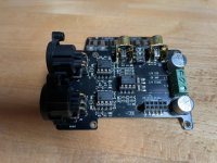
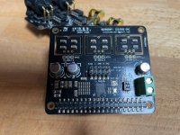
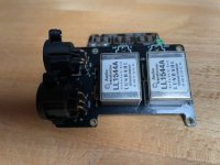
What we found inside :

- Dual Merus MA12070 chips
- OPA1678 op amps
- NJW1194 digital volume chip
- A great Meanwell SMPS PSU 300W
- RCA inputs
- XLR inputs
- Sub out
- Banana speakers

I listened to the amp with my favorite Audiophile Playlist for 1 hour yesterday, it is really impressive @ first listening. Seems promising in relation to its ration performance / price.

Since I own almost all TPA325X in the market and some Hypex Ncore and Purifi at home, I can tell you that it is pretty good even very good in comparison ... for the little that I have heard.

Should be nice to have the ASR review soon ) Fingers X.
In fact the amp is using exactly the same components as the SMSL DA 9. The design is just different.

I have no real idea of ​​the veracity of the data relating to its real power ... but I can confirm one thing, it does not lack potency! If I set the volume to -03DB and stream from my LG V30 in LDAC, at 30% of the volume, I am largely covering my living room of around 35 / 40m2. This is an amp that is rather SQ oriented.

I will let ASR giving us a real feedback about the measurements.

I can tell you that next to my Ncore and a TPA3255 (top of the range, Jlester, DrMordor) it does not blush at all! It has a somewhat different sound signature. We find a little the soundstage of the TPA325X and that of the Ncore, it is a little different however but nothing to complain about, it is performing very well here. I find in the signature of the MA12070 chip a particular roundness in the mediums, the bass is quite muffled but very present. The highs are very similar to the Ncore. The amp is also absolutely dead silence between tracks, the meanwell PSU helps here.
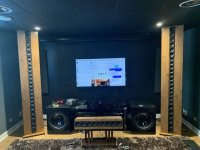
My setup :

Gustard X16 DAC
Sabaj A20 (XLR > full balanced mode)
Other amps : Hypex Ncore / Purifi / TPA325X
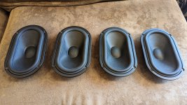
High end floor 2.5 way speakers, Ribbon tweeter (handmade in France by the way)

Streamer : LG V30 via LDAC
Source : Audiophile Master Sound HD Playlist

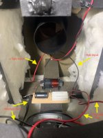
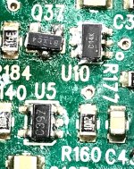
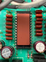
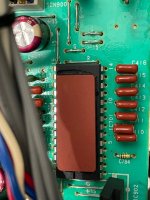
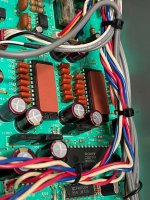
I tried to open the case to take pictures of the module, the PCB etc .. but unfortunately it is complicated to dismantle ...
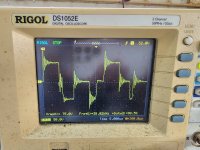
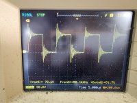

Videos :

Sabaj test 1

Sabaj test 2


Pictures :


Capacitors for crossover development

Hello all, I have a question on crossover design.

I'm putting together a 3-way using the SB Acoustics SB15CAC as the mid and the Dayton RS225-8 as the woofer. I've measured the driver responses in the box, and have been modeling with VituixCAD to design a draft of the crossover design.

My question(s) - for the woofer/mid crossover, I need some hefty capacitors (from 80 to 120 uF). Can I construct the initial design of the crossover using nonpolarized electrolytics to make sure I have the frequency response correct (and then go to more pricey/better capacitors later)? I'd hate to drop $200 on caps and then find out I need a slightly different value...

Diodes and Power Supply Modeling in LTSpice

Hit me I might be being too literal and LTSpice doesn't "see" any differences in diode specifications, since does not allow them to be installed under components.

I modeled this: http://www.r-type.org/addtext/add158.htm (sans transformer since seems redundant and no pots since not an option in LTSpice), surprisingly got no errors and getting voltage, however, I don't know how to write and/or set up input voltage so getting way too low of a voltage out of HT (a few volts when probed).

Does anyone know how to set up an input for a power supply?

If not, fine, I now see my new assumption about diodes is correct, to LTSpice all the same. Plus, succeeded in creating a model 95 percent from scratch (copied the scripts @jcalvarez provided in another model). Though be nice to get it working, like to probe around and gain more understanding of circuits.

Thanks in advance! 😀

Help pick a design for odd location

451444BD-C250-4530-AD22-AEFCF1DB5ECD.jpeg


Hi everyone!
I want to build a cabinet containing 2 speakers to fit in the space directly below the TV. When I built the shelves I planned on building a pair of speakers to sit on either side of the television. Well, after the shelves I built a pair of the Wayne Parham
Four pi using jbl 2226h woofers for my basement system. They really are amazing and Im sure I will be disappointed with a small set of bookshelf speakers now. The space is 19” high, 14” deep, and 70” wide. Im considering 2 designs. The Michael Chua Osprey 12 and the Zilchlab delite 10 econowave.

https://www.ampslab-spk.com/2021/08/23/osprey12/

https://techtalk.parts-express.com/showthread.php?p=1639915#post1639915

I tried to link to them above. This will be mostly music streaming with some movie watching. Clear natural dialog is more important than impressive deep bass for the movie watching. I would like strong 80 hz or lower for satisfying musical playback though. I wont be using any sort of dsp for this system and would like to not need a sub. The room is 14 x 30 x 8’ and all hard surfaces except a thin area rug. Im guessing the osprey 12 is more of a sure thing as Michaels designs get alot of praise and I have the space to build each 12” woofer its own 100 liter sealed cabinet. What I like about the delite 10 is the constant directivity waveguide and the rheostat on the compression driver could be a nice feature. With this design I think I will need a vented enclosure which would likely require some experimentation to get sounding natural in the odd location they will be placed. I do intend to angle either design up enough to aim above the person sitting on the couch 15’ aways head.
All thoughts and opinions on how to get this right are appreciated!

Foster E100T10

Awhile back adason was praising these after getting some from PE at buyout prices ($14.95? ea.) so I figured at that price i‘d get a few (8 to be exact) they were hanging around waiting for me to make an adapter plate to try them on my burhoe/genesis franken speakers…….then one day i’m poking around fleabay and find printed adapters for this tweeter but not the right size to match the burhoe plate……so i contact him and he says he can custom make them for me for the same price ($20 pr.) if i send him a precise drawing….awesome! Here’s his handle https://www.ebay.com/usr/chris-1111 …….says he can make any custom plate needed.

So today I decided to put them together and am quite impressed, as per burhoe design I ended up up with a single series cap (2.7uf) which calculates to 9.8khz which is where my mid starts to roll off, sensitivity was perfect to run straight no l-pad…….gotta tell ya they’re pretty awesome even at high volume…….clear,calm,collected, and best of all my lacking air is back! Maybe a little more laid back than i was used to but i’m thinking i was used to distortion! There’s much more detail just a little softer……less tiring to listen to for sure. I might have a bit too much overlap @ 8-9k as its a bit hotter there than it was with my previous ‘Human speakers’ replica inverted tweets. (reason for change was the Humans fell out like a rock @ 14k ……no air) will probably try a little smaller cap if it continues to bother me.

Well thats the good news…..bad news is when I went get a link from PE to put in here but they are gone! Some might still be found elsewhere with enough digging? That is if anyone is interested in them.

E05C58A1-06C7-448B-8FFB-68E2F948CA26.jpeg B69C3DBB-1CBC-4627-8484-DA1CECD6D970.jpeg

Interstage Transformers

New CineMag CM-2800g. Custom wound for me, never used, new in the bubble wrap. 1 pair. Specs: 2:1, 20Hz to 20KHz, Air gap for 30mA unbalanced DC. Designed for use with 6BX7 as driver for 300B. New $150.00 asking $100 obo.

AES PT-157. Specs: Nickel core, Primary 10K 10mA dc, secondary 90K. Used but good condition. $40.00 obo

Attachments

  • CineMag1.jpg
    CineMag1.jpg
    96.6 KB · Views: 798
  • CineMag2.jpg
    CineMag2.jpg
    96 KB · Views: 797
  • PT-157.jpg
    PT-157.jpg
    198.2 KB · Views: 813

Can anyone identify this diode?

This capacitor-diode series combination is from a Sherwood RX-4010R receiver that I am recapping. I believe this Sherwood was manufactured sometime around 1993. Apparently these parts were a factory change that was added on (the cap is the same type used throughout the unit). The parts are undocumented, they do not appear anywhere in the Service Manual.

The diode has the marking " Z3.3" on its body. So I would assume it is a 3.3 volt zener. But the way it is used in circuit, it makes no sense to me that a zener was needed.

Is there any way that the "Z3.3" marking might possibly NOT indicate that it is a 3.3v zener? I just want to replace both parts with original equivalents.

Thank in advance...

Attachments

  • DSC08115cr.JPG
    DSC08115cr.JPG
    329 KB · Views: 105
  • DSC08145!cr.JPG
    DSC08145!cr.JPG
    211 KB · Views: 112

FBT Pro Maxx 12a unknown SMD parts

Good day to everyone. I hope all is well and good. I am repairing an active speaker FBT Pro MAxx 12a. And as shown in the photo I am having a difficult time in finding the correct part number of these parts Q37, U10 and U5. The SMD code written in each component is no where to be found in the SMD code book. Can anybody share with me the particular part numbers of the SMD components. This circuit by the way is connected to the driver of the output mosfets. If you have schematic diagram you can share as well will be very much apreciatted. Thank you very much.

Attachments

  • FBT Pro Maxx 12a.jpg
    FBT Pro Maxx 12a.jpg
    277.5 KB · Views: 143

New Portable Speaker Project

Hi, I recently built a portable bluetooth 2 way mono speaker which runs off a Makita 18v battery. Had a lot of fun doing it so now looking to build another one, but a different style and bigger and bassier.

I am looking to use 2x full range speakers, stereo left/right. I am thinking of using:

Faital Pro 4FE32 Neo - 4" 30W 8 Ohm 91dB


And for the bass either:

1x Beyma 10BR60V2 - 10" 100W 8 Ohm 92dB
or
1x Beyma 12BR70 - 12" 125W 8 Ohm 93dB


My questions:

1. Would the 2x 4" be able to keep up with the 10" or 12" sub?

2. If yes, where would you reccomend crossing them over at?

3. Is there a formula to work out what size, mid/top to bass ratio at all?

I understand to look at the driver sensitivity dB itself. But the physical size of the driver has an impact too on sheer volume, which is where im unsure how to match it. As its going to be portable, i dont want to overkill the bass and have to turn the gain down loads when i could of just used a smaller driver. Whereas on the flip side i dont want to under do it as it will be used for bassy music.

My previous portable speaker was just a mono 2way so i knew what i was using would cope fine together and the crossover points were roughly dictacted by the tweeter anyway. But struggling a bit to find the answers and dont want to waste money on them to find out they arent suitable.

Amplifier ill be using is a Sure Wondom 4x100w Jab5 DSP amplifier. 1 channel for left, 1 channel for right. Then the remaining 2 channels bridged for the Bass.


Cheers 👍🏼

TDA1541A x 2 from Sony CDP-337ESD

Hi all,

I have 2 x TDA1541A for sale. As shown in photos they are still in the unit but can be carefully desoldered and shipped if anyone is interested.

For a bit of background, the unit is a Sony CDP-337ESD. I purchased two of these second hand in Japan (where I live) as a bit of a project. I've established one of these needs a new laser, so I have decided to give up on it. The second unit is working and sounds fantastic, by the way.

Internally they look quite different to photographs of non-Japanese units I have seen on the internet. The PCB is green (not white), and the DAC ICs have ceramic dampening applied.

I know there's a lot of discussion about counterfeit TDA1541As, that's why posting with the chips still on the PCB and explaining all this background 🙂

Finally, I've read that not all CDP-337ESDs did contain the A variant. Short of removing the ceramic dampening I'm not sure I can prove what they are. Not trying to mislead anyone here.

Open to offers or questions.

Thanks.

Andrew

Attachments

  • tda1541-0.jpg
    tda1541-0.jpg
    592.6 KB · Views: 287
  • tda1541-1.jpg
    tda1541-1.jpg
    560.8 KB · Views: 229
  • tda1541-2.jpg
    tda1541-2.jpg
    720.7 KB · Views: 338

Anyone got Jamo 707 driver parameters?

Hi,

I've got a pair of Jamo 707 (label on speaker input says 707a) produced in early 90's. With a decent and powerful amp they still sound impressive.

However, since I'm trying to tweak the xover I would really need parameters (T/S for instance) to create frd and zma files for xsim in order to balance tweeter, mids and woofer sections.
The drivers are:
Tweeter 38822
Mid 20255
Woofer 20383
PCB name is 53564

Any help much appreciated.
  • Like
Reactions: LeifB60

Discussion split from - Anyone making Apogee bass panels?

All,

You should be buying the latest ribbons designed and manufactured by Graz in Australia. He bought all rights and designs from Apogee and spent a lot of money on cnc equipment and improvements since he started manufacturing everything you need since early 2000. I’m buying all new ribbons, socks, foam kit and ribbon wiring/clamp kit from him tomorrow. He’ll only send the bass panel to an authorized installer he trained. Too easy to screw up. I’m totally redoing my Duetta Signature Series IIs, including a new automotive grade paint job very soon. Note, Graz’ website needs updating, but Graeme is very responsive. So are Rich at True Sound Works and Bill Thalmann at Music Technology. They are top notch. Links below.

Repairs / Apogeeribbons

Vintage Stereo & Turntable Repair | Music Technology Inc.

TRUE SOUND WORKS AUDIO, INC. - HOME

Bigger 2.0 desktop speakers vs smaller 2.1 system?

I'm in need of desktop speakers that fit under my triple monitor setup, 13-14cm high.
I have a 7x100W HT amp and an 8CH DSP, so no need to design crossovers or use plate amps.
I already own a pair of tang band w2-2243s widebands that I planned on using for these desktop speakers, but they shouldn't be used much under 500Hz, contrary to Tang band.

I want the system to be "full range".
I planned on using the Tangband W5-1138SMF as midbass in a 6-10l ported or PR enclosure tuned to 35-40Hz.
But I also want to go as cheap as possible.
So I found the Omnes SW5.01, with similar specs. It has only 7mm of xmax instead of 9mm that the W5 has, but it is half the price.

Now I wonder, what would you recommend?
  • Using 2x Sw5.01 per speaker in 16l ported enclosures tuned to 33Hz in an MTM style box on it's side.
  • Using 1x Sw5.01 per speaker in 6-10l ported enclosures tuned to 45-35Hz and an SW8,01 sub in a 40L box tuned to 28Hz.
  • Using 1x W5 woofer per side in 10l ported enclosures tuned to 35Hz.

What do you think would be the best for audio quality?
Also, tuning a 6-10l box that low and staying under 20m/s port air speed with 50-80W is hard if not impossible. Any tips?
The 16l box is also stretching my desk space to the limit.
1678742936628.png

Green: W5, Orange: 1xSW5.01, Pink: 2xSW5.01, Purple: SW8.01
All have 80W of power and HPF set to not exceed Xmax.


Any other cheap recommendations are also welcome.

New Speakers or New Amplifier to Increase Sound Stage

I’m looking to make an improvement over my current system but can’t quite decide on the best route being new speakers or a new amplifier.

Currently I use a pair of Jeff Bagby designed Piccolos. And as I have posted other places on this forum, I am very happy with sound quality from them. The dynamic range, low distortion, and particularly the high-end clarity, are outstanding and very satisfying.

So, what I’m looking for now is just to expand the sound stage. I listen to classical music and opera and although it sounds very good the music is contained to a rather limited width. Essentially all of the sound appears to be between the speakers. There is some depth to the sound stage, but limited width. The image is rather small and compressed.

To make matters somewhat more difficult I am listening in a fairly small room. It is only 10.5’ wide by 11’ deep and 8’ high. Plus, there is very thick carpet covering the entire floor. I sit about 2’ from the rear wall and the speakers are about 6’ apart and 2’ from the front wall.

I understand that the small room creates limitations on the sound field that can be achieved. Nevertheless, I would like to optimize things as much as possible in order to increase the size and depth of the sound stage

So finally, to the question. Am I better off building a different speaker design or is the sound stage not going to change much even if I do? In other words, is the small room and speaker placement going to be the dominant factor that determines the sound stage.

Or is it possible that a different amplifier can increase the sound stage for me without having to build new speakers. Right now, I am using a Denon AVR, which admittedly is not a high-end audio component. And I am willing to invest in a good stereo amp designed specifically for music if that will really make a difference in the width and depth of the sound stage.

New speakers or new amplifier. Maybe both are needed, but what should the first move be?

Q: Pre-Amplifier for Digital Oscilloscope

Hi,

I have ATTEN ADS 1062CML 60MHz 2-channel digital oscilloscope and it has quite poor input sensitivity. My idea is to build 2-channel low-noise pre-amplifier. I'm mostly need oscilloscope for debugging vacuum tube audio circuits. Occasionally I come across article "Measure Milli-volts with Decade Amp" in Radio Electronics magazine 1960-09, which is designed as add-on for voltmeter or oscilloscope. It has gain of 100, 5Hz - 1MHz bandwidth, 1M input resistance, 1K output impedance, and because of vacuum tubes (3 x 6AK5), immune against input overload. Noise with input shorted is 300uV. Overload input voltage is 0.25V.

Schematic and the whole article in attachment. My idea is to build 2 channels, power it on from separate HV windings of toroidal transformer, and make separate GND for each channel.
Also, I would like to replace 1MOhm grid leak resistor with a series of 3 to make 1/10/100 attenuation of the input signal, so no need for countless switch of the oscilloscope probes between this pre-amplifier and digital oscilloscope.

What is your opinion? Is this a good idea? Any suggestion is greatly appreciated.
Thanks in advance.

Attachments

Choke vs inductor

What’s the difference between a choke and inductor?

Conclusion (12/03/2023)

Thought it might be useful to write a conclusion. People generally seem to think that choke is just another word for an inductor. There were some other comments that suggested the choke is generally used when the application places emphasis on passing DC or low frequencies, e.g. power supplies. For this purpose some optimisation of the winding and core may be used, for example core with air-gap or air-core, accepting higher winding capacitance (reducing the bandwidth of the choke) to improve in other areas.


For example, I’m making an LR filter, I need an inductor of about 2mH and it will pass about 1.5Arms. This is an audio filter so will operate between 20Hz-20kHz

Some options from Bourns:

5700 Series High Current Inductor and the 1140 Series High Current Choke.

The 5719-RC Inductor 2250uH (at 1kHz)
1.75A max.
0.95 Ohm DCR
1350uH min. at rated current.

The 1140-222K-RC Choke 2200uH
2.4A RMS
4.4A Saturation
0.494Ohm DCR

The choke seems a better choice, it has lower DCR and high current and saturation.

Why wouldn’t a choke be a good choice?

Analogue devices MAT03 & MAT02

I have a pair of NOS MAT03 and MAT02. Transistors. Never used or removed from anti static foam and still in the original packaging. They were meant to go into an Elektor high speed pre-amp many years ago but never got around to building it. Now I'm to old, so its time to have a clean out of these and many other NOS parts I have. Just not sure what to ask in terms of price so thought I'd post these initially and see what sort of response I get.

Attachments

  • Photo1.jpeg
    Photo1.jpeg
    702.7 KB · Views: 194
  • Photo2.jpeg
    Photo2.jpeg
    1 MB · Views: 196
  • Like
Reactions: carolus and panos29

JP23 v1.5

Ok I'm kind of at my wits end here.

Got a JP23 v1.5 on the bench with an illuminated protection light on. Class D type 4. No output mosfets blown, but the output filter inductors had gotten a little warm and melted the factory applied insulation. I assumed the inductors had shorted out.

Removed the inductors, unwrapped 1.5 turns, applied my own heat shrink to the exterior of the wires, rewrapped the inductors and tested inductance. 0.13mH with 0.8ohm resistance on both. Soldered both back in and tested. Amp came out of protect!!

Shut down amp, ziptied both inductors in place tightly the repowered on and the amp is back in protect. Oooook.

Repeated previous procedures two more times and amp refuses to come out of protect. I cannot find any place were the inductors are shorting out.

What gives?

How do I proceed at this point?

Schematics for Solton Commander 2000

Hi,
I've started a small hobby project that involves restoring an 8-channel PA mixer,
by the name Solton Commander 2000.
I had troubles switching it on, but that was quickly resolved when having a look at the power switch that had some old tear on the metal inside, which cut off the connection - so now she's turning on but I still have a small issue.
there's a black wire that's seems to have melted off somewhere. It's supposed to be connected to the Monitor out channel, and it's not the only black wire so I can't just assume - therefore I'd like to hear if anyone, anywhere, somehow, I don't know - would have the schematics for such a model or maybe a model somewhat similar?
I know that it is from 1984, and I've tried googleing, but it seems I'm the only guy on the internet with such a device - except for a polish user somewhere on some polish eBay in 2009 that sold his.. so any help whatsoever would be greatly appreciated.
The Tape delay unit has never been used, and I also need to find some tape for that, so if anyone has any recommendations for what kind of tape to buy, that would also be greatly appreciated! 😀

Have a nice day everyone,

-Magnus

HVFORLESS Power Supply boards are back

I know a lot of hobbyists here have bought my boards off Ebay in the past. They're still mentioned in many threads here. I had to take a year or so off and pulled the adds. Anyway, they're back up. Just look up the user HVFORLESS and you'll see what I have for sale.

So far I have the following listed:

LV board - allows you to get 6.3VDC from a 6.3VAC transformer winding. Also has a voltage doubler circuit that can be activated with a jumper and trimpot.
HV board - great universal board for any HV tube project. Every conceivable option is accommodated including negative bias.
Pre-Amp board - in my opinion the best preamp power supply board out there. Tons of options and can handle tons of current.

I also plan to list my OTL Tube Headphone Amp White Cathod Follower board. This board combines the pre-amp circuit above with a white cathode follower headphone amp circuit. Best sounding headphone amp I've ever heard. This listing will come with additional info to help with chassis construction.

Jolida JD 1301 with LM1875T

I went fishing inside my JD 1301 amp, originally in an attempt to locate the LM1875T feedback resistor. (I was hoping to make the feedback remote sensed)

While there, I caught a couple of 100 uF Aluminum-Electrolytics in the feedback network, to ground. I never liked the sound of this amp compared to my Jolida JD 102B, an all tube unit I have running JJ EL84s in triode mode. I figured out why.

I appreciate this forum where I read that it's basically OK to eliminate these caps. I did so and measure ~30mV on each channel's speaker outputs, which I also read wont be a problem.

Making this one change has rendered the little amplifier wonderful sounding, on par with the tube unit if not better. I assume the idea behind this amp is a tube stage providing some 2nd order harmonic distortion, followed by a power amplifier with zero distortion - at least at the levels I listen at.

This architecture works across a wide range of system implementations, from a little easy-peasy amp the JD 1301 is, to that which was reviewed in this Stereophile article Lamm Industries L2 Reference preamplifier | Stereophile.com

There, we have a $13,600 preamp with "an absolute dominance of the second-order harmonic", followed by a pair of Krell 350MC monoblocks. Not claiming the little Jolida has the same sound as $50K worth of hardware, only the same idea.

And once I got rid of those little 100uF Al-Els in-the-signal-chain buggers, it sounds a lot more in the right direction. Just in case anyone has this amp, or is using the "stock" LM1875T circuit, that cap makes a difference. It should be eliminated, or of the same quality as the best cap in the signal chain.

Yes, I should probably put fuses in the speaker wiring - and hope the coupling caps from the tube stages never leak. I realize the LM1875 part is coupled all the way to DC now, opening the door for such trouble.

If I knew that cap was there, I would have never bought the amp in the first place. They put polyprops coupling the tube outputs, then these little POS - with AC audio across them (worst case) no less, as it's a +/- power supply to the chip. Hope this helps someone. Thanks for the info being here and to the folks putting that here over the years.
Projects by fanatics, for fanatics
Get answers and advice for everyone wanting to learn the art of audio.
Join the Community
507,636
Members
7,881,491
Messages

Filter

Forum Statistics

Threads
405,923
Messages
7,881,491
Members
507,636
Latest member
tom.mccann