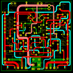
Building a 30 watt class A amplifier using the attached LTSpice schematic and pcb layout. I have the prototype board set up on the test bench with a GW Instek GPE3323 regulated power supply, an OWON HDS242S scope, OWON XDM1041 bench multi-meter and an Instek GAG-510 signal generator with RCA connector.
First I tested without the output and Vbe transistors installed, joining collectors Q4 and Q7 to the NFB. Power supply set to +/- 33 volts DC. The ground reference for signal and power are connected to the common of the power supply. All voltages at every node match the simulation results of the LTSpice run ("design"). Connected the signal generator and ran a test signal and the output waveform was a perfect sinewave and matched the simulation results from zero to 28V clipping.
I then connected the output stage transistors Q11, Q12, Q13, Q14 and Vbe Q10 to a heat sink and connected their leads to the pcb with wires. Turned the bias all the way down and started it up. All voltages matched design. Full off bias was 30mA. Turned up the bias but the current stayed at 30mA with every turn of the pot screw until it turned on at 300mA (could not adjust between 30 and 300mA). After that, the current rose proportionally to 2.4A at the max trim pot setting. Left it on at 1,2A bias for a few hours and all measurements remained constant and correct.
Problem:
When I plugged in the signal generator (or touched the input with a probe, wire, etc) the output current increases without touching the bias setting and the voltage across the Vbe transistor doesn't change. The scope shows a distorted output waveform that somewhat resembles a sinewave but the scope frequency counter shows hundreds of kHz of grunge. If I start turning up the bias, the idle current increases faster and appears to have no limit -- it goes as far as the P/S current limiter is set. Also noticed the bias current climbed much less when probes were attached across the collectors of Q4 and Q7 (to measure bias voltage).
After many attempts, this is a summary:
Bias all the way down with the signal generator plugged in jumps the current from an idle 30mA to 600mA and the scope reads a distorted signal. Touching the collector of either Q4 or Q7 with a screw driver returns output idle current to 30mA and the scope reads a perfect sinewave from zero to clipping at the set frequency. Grasping the heat sink with my hand also returned the idle to 30mA and cleaned up the signal to a perfect sinewave (I then grounded the heat sink and this stopped from happening again).
Turning the bias up to turn on Q13 and Q14 with the generator plugged in, the idle current jumps to 600mA (or above) or above and touching the collectors Q4 or Q7 does nothing and the output signal is distorted.
Both grounds of the pcb are connected to the P/S common through a 10-ohm resistor paralleled with a 0.68u cap. It makes no difference if the P/S common is floating or earthed.
Any help is greatly appreciated
Attachments
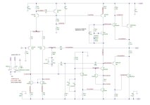
Cascodes are often tricky to stabilize in my experience - at the very least give Q7 a base stopper R. I have also had problems with Sziklai pairs oscillating.