You are using an out of date browser. It may not display this or other websites correctly.
You should upgrade or use an alternative browser.
You should upgrade or use an alternative browser.
Filters
Show only:
Floorstanders made of composite MDF?
- Multi-Way
- 10 Replies
Hey people,
The next speakers will be way better then the last 😉 (the last aren't bad, they are really good, but ...), but I got ideas I want to try out.
For example a cheap composite material made of two pieces of MDF. I thought, I'll take one piece, 10mm thick and mill out 2-3mm of the complete surface, except of maybe 6-8mm on the edges. The milled out space will be filled with silicone, and a 8mm thick second plate will be put on top. On the inner plate will be also mounted some screws as inward pointing studs. The edges will be glued as usual. the completed plates will then be screwed to a frame of soldered aluminium-profiles.
This will be affordable, and I hope give a good speaker-case.
Thoughts?
best regards
Jochen
For Sale Premium electrolytic caps (Jensen, Rubycon black gate, ASC Blueline)
Jensen Audio Grade electrolytic caps 47000uF/16V 4 terminal type.
SOLD
Rubycon black gate NH 220uf/160V Non polarized
SOLD
Rubycon black gate NH 100uf/160V Non polarized
SOLD
Rubycon black gate NH 68uf/350V Non polarized
SOLD
ASC Blueline.
SOLD
SOLD
Rubycon black gate NH 220uf/160V Non polarized
SOLD
Rubycon black gate NH 100uf/160V Non polarized
SOLD
Rubycon black gate NH 68uf/350V Non polarized
SOLD
ASC Blueline.
SOLD
Opamps for mixer upgrade/replace
Trying to learn about opamps over here.
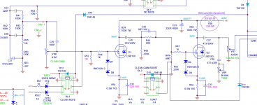
Looking at this schematic for a mixer I have, it has a 5532 opamp in the U1 first stage and then three 4558 opamps (shared between two channels) for the EQ and effects send in U2 U3 U4 U5.
From what I've read it sounds like 4558 is pretty much bottom of the line for acceptable audio use. Can they be replaced with 5532 in these positions? Is there something else that would actually improve it, in a DIP-8 package? It's a low-end mixer I'd like to improve a couple channels, but not so much that I'd want to bother with soldering caps around to stabilize more sophisticated chips. It sounds okay but pretty dull in the high frequencies and very sloppy in the lows.
Would 5532 work here, and if not, could someone tell me what the necessary parameters for this kind of circuit? Thanks in advance.
Accuphase F-25 crossover boards for sale
- By Armand
- Vendor's Bazaar
- 1 Replies
I have made aftermarket filter boards for the Accuphase F-25.
These boards can be custom fitted with capacitors and resistors for any frequency from 50Hz to 15kHz.
The physical size and connectors match the original boards exactly.
This is a board custom made for 50Hz.

This is a measurement of a 150Hz version with the three different slope settings of the F-25

There is a 0,1dB and 5Hz error, but that is within the limits of the F-25 itself.
I use 0,1% resistors and 1% capacitors for better tolerance than the original Accuphase filters I have measured so far.
Resistors are Susumu metal film.
Capacitors are the superior C0G type for absolutely lowest distortion.
Any interest?
These boards can be custom fitted with capacitors and resistors for any frequency from 50Hz to 15kHz.
The physical size and connectors match the original boards exactly.
This is a board custom made for 50Hz.
This is a measurement of a 150Hz version with the three different slope settings of the F-25
There is a 0,1dB and 5Hz error, but that is within the limits of the F-25 itself.
I use 0,1% resistors and 1% capacitors for better tolerance than the original Accuphase filters I have measured so far.
Resistors are Susumu metal film.
Capacitors are the superior C0G type for absolutely lowest distortion.
Any interest?
FS Elekit 8600S, 8900 and 8550 tube integrated amps
Moving, downsizing and wont have the space to keep this or keep building. I built these 3 and they only have 50 hours on each of them. 50 hours was burning in and testing to make sure it functioned before I sold them. They dont have any damages and considered new, they come with the build manual and tube cover. Shipping to Continental US only due to high shipping costs.
Elekit 8600S $1800 :
Elekit 8800 - $1800:
Elekit 8900 - $1550 :
Prices do not shipping. Paypal with 3% or with Paypal friends and family.
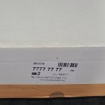
Reach out to me for more details or photos. Photos below show white specs - that is just from the paper towel I used. Tubes are not included in this price.
Thx
Elekit 8600S $1800 :
- Lundahl transformers
- Takman 2% resistors
- Mundorf Silver Gold caps
- TKD volume
Elekit 8800 - $1800:
- Lundahl transformers
- Takman 2% resistors
- Jupiter caps
- TKD volume
Elekit 8900 - $1550 :
- PRP 1% resistors in most places
- Audio Note resistor pair in signal path of amplification stage
- Audio Note caps
- TKD volume
Prices do not shipping. Paypal with 3% or with Paypal friends and family.
Reach out to me for more details or photos. Photos below show white specs - that is just from the paper towel I used. Tubes are not included in this price.
Thx
Is this normal? SMSL DAC offset
- By Siberia
- Digital Line Level
- 23 Replies
These are the DC mV readings on my SMSL Sanskrit MK II DAC output while music is playing. Are these readings, which seem high to me, normal?
Login to view embedded media
Login to view embedded media
Amplifers for 53v smps
- By momomo67890
- Class D
- 7 Replies
I found about 20 able tech smps in a box in my mom attic was wondering if I could get some recommendations on what to build with them
TS parameters - Volt B2500.1 bass driver
I have started to design a pair of 3 way active speakers using a pair of Volt b2500.1 woofers that I bought in the late 90s.
I plan to use these with a pair of pmc 3" soft dome midrange drivers and some scanspeak r2904/700000 tweeters that I also acquired a long time ago. A pair of Hypex fusion fa253 plate amps will power them. Given the low compliance of these drivers, I plan to use a bass reflex design.
Incidently, these midrange drivers are manufactured in-house by pmc and not supplied by Volt as is often stated. These are crossed over at 380hz (as atc) by pmc, so are much closer in spec to the atc sm75-150s than the Volt vm752s.
I have various datasheets for the B2500.1s which date from 1997 through to 2014. These give fs as being between 25hz and 39hz, depending on vintage. Obviously, there have been changes made over the years.
As such, I have been trying to measure the ts parameters for myself. Following the advice given by Vance Dickason (Design Cookbook) and by Rod Elliott (ESP), I have broken the drivers in for several hours at a low frequency, then taken measurements using the current source method (using a 10ohm series resistor).
At small signal levels (<1v), I measure fs at around 50hz. When I up the signal to 6 or 7 volts, this drops to around 39/40hz. (Vance Dickason states that fs should increase with a rise in signal??). Either way, it's a country mile away from the 25hz that the 1997 datasheet is giving.
I don't know what I'm doing wrong or why my measurements are so far away from those given by Volt. These are £400 drivers at current prices, so are presumably manufactured with some care. Why are measurements taken at low signal levels, which are not representative of real listening conditions, when clearly this has a bearing on the enclosure tuning?
Any ideas?
FireStick ( and / or ) FlexBox volume control ....
- By hitsware
- Everything Else
- 5 Replies
Will ( Should ) the volume controls on the remotes
that come with these devices work if the device is
plugged into a HDMI monitor rather than a TV ?
that come with these devices work if the device is
plugged into a HDMI monitor rather than a TV ?
Chinese audio noise filters?
- By grandwazoo
- The Lounge
- 5 Replies
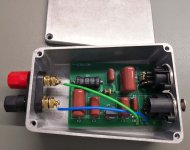
I bought one of these filters from Amazon to quieten an annoying hum on my workshop system (which has 2 sound sources, one a PC, plugged into one switch box). It works remarkably well, but how? I can't find any info on the contents of the sealed shell, and I don't really want to break it to find out... does anyone know what's inside?
Minimalist TPA3250 Amplifier with quality components..
Hi all,
As you know, TPA3251 has not been available from the main suppliers for a while and I think it will not be available for a long time.
So I would say decided to design a PCB for the TPA3250, which is the closest sibling of the 3251 (on paper at least).
Since the TPA3250 has a different pin configuration than the 3251, it was necessary to design a different PCB.
Provided that the basic design logic remains the same as TPA3250D2EVM, since the LM5010 is no longer available, I used XL1509 working at the same frequency as a step down regulator, an extra LC filter for its output and solid caps for bypass at the output. I also used a standard 78M12 as a linear regulator. And on the analog supply line has audio grade (like Silmic 2 or UKW) bypasses and parallel C0G 100nFs and X7R 1uFs.
I used a solid state power switch on the PCB and the MIC6315-31D4UY-TR, which provides an integrated 1.1 second reset delay. This will prevent pop during both power on and power off sequences.
For the main bypass capacitors, I added 2x Rubycon ZLQ 2200u/35v (16x25mm) and 100nF C0G and 1uF X7Rs in parallel.
At the output, there are UA8014-ALD 10uH double chokes, (produced by Colicraft especially for the TPA32XX series) 1uF MKP and 1000pF FKP capacitors in parallel.
All the power lines and the linear regulator are on the bottom side.
On the signal line no vias used.
....
So the result was a very minimalist PCB design, as you can see.
All lines were kept as short as possible, PWM circuitry and analog circuitry were kept as far away as possible to avoid RF interference.
If you have the opportunity to examine the design, I request you to express a positive or negative opinion, and to let me know if there is a design element that you would like me to change.
Of course, I expect suggestions from DIYers who want to make the project together
Best regards,

 .
.
As you know, TPA3251 has not been available from the main suppliers for a while and I think it will not be available for a long time.
So I would say decided to design a PCB for the TPA3250, which is the closest sibling of the 3251 (on paper at least).
Since the TPA3250 has a different pin configuration than the 3251, it was necessary to design a different PCB.
Provided that the basic design logic remains the same as TPA3250D2EVM, since the LM5010 is no longer available, I used XL1509 working at the same frequency as a step down regulator, an extra LC filter for its output and solid caps for bypass at the output. I also used a standard 78M12 as a linear regulator. And on the analog supply line has audio grade (like Silmic 2 or UKW) bypasses and parallel C0G 100nFs and X7R 1uFs.
I used a solid state power switch on the PCB and the MIC6315-31D4UY-TR, which provides an integrated 1.1 second reset delay. This will prevent pop during both power on and power off sequences.
For the main bypass capacitors, I added 2x Rubycon ZLQ 2200u/35v (16x25mm) and 100nF C0G and 1uF X7Rs in parallel.
At the output, there are UA8014-ALD 10uH double chokes, (produced by Colicraft especially for the TPA32XX series) 1uF MKP and 1000pF FKP capacitors in parallel.
All the power lines and the linear regulator are on the bottom side.
On the signal line no vias used.
....
So the result was a very minimalist PCB design, as you can see.
All lines were kept as short as possible, PWM circuitry and analog circuitry were kept as far away as possible to avoid RF interference.
If you have the opportunity to examine the design, I request you to express a positive or negative opinion, and to let me know if there is a design element that you would like me to change.
Of course, I expect suggestions from DIYers who want to make the project together
Best regards,

Strange Power Supply McIntosh MA6100
- By 2N6658
- Power Supplies
- 9 Replies
Hello,
I have restored an old Mc Intosh integrated amplifier MA6100, works fine.
I saw something quite strange in the PSU :


I don't understand why they make high tension (110 VCC), then drop about 100 V in R400 (3,6 k / 10 W) to finally have 10 V 😕 ... Making 12 VCA and then regulate it to have 10 V was possible and less expensive, and with no big hot running resistor !
What is the adventage of making such a power supply ?
Note : 110 VCC only goes to amplifier, no others circuits use this tension...
Thanks for your help 🙂
Please apologize for my english, I'm French 😉
Edit :... humm is it because it was less expensive to make a symetrical double secondary 2 x 150 VAC than 1 x 150 VAC and 12 VAC... ???
I have restored an old Mc Intosh integrated amplifier MA6100, works fine.
I saw something quite strange in the PSU :
I don't understand why they make high tension (110 VCC), then drop about 100 V in R400 (3,6 k / 10 W) to finally have 10 V 😕 ... Making 12 VCA and then regulate it to have 10 V was possible and less expensive, and with no big hot running resistor !
What is the adventage of making such a power supply ?
Note : 110 VCC only goes to amplifier, no others circuits use this tension...
Thanks for your help 🙂
Please apologize for my english, I'm French 😉
Edit :... humm is it because it was less expensive to make a symetrical double secondary 2 x 150 VAC than 1 x 150 VAC and 12 VAC... ???
Bookshelf Kit - compete with P3ESR XD
Hi,
I have a set of Harbeth P3ESR XD on my desk. I do like them a lot.
I feel like building something, and thought a pair of bookshelf speakers that are up around that level (or beyond) and maybe offer a different flavour. Then I can rotate the two sets and keep things interesting.
So only real constraints would be;
I have a sub so they don't need to dig too deep, sub and crossover all handled by a NAD M10 V2 on my desk.
Thanks for suggestions! Do appreciate it.
I have a set of Harbeth P3ESR XD on my desk. I do like them a lot.
I feel like building something, and thought a pair of bookshelf speakers that are up around that level (or beyond) and maybe offer a different flavour. Then I can rotate the two sets and keep things interesting.
So only real constraints would be;
- Not large bookshelfs, P3ESR are quite small, bigger fine, but not 350mm deep, 400mm high sort of big
- Good nearfield performance (desktop, will be using DIRAC though)
- Front ported or sealed probably best
I have a sub so they don't need to dig too deep, sub and crossover all handled by a NAD M10 V2 on my desk.
Thanks for suggestions! Do appreciate it.
Fasten seat belts. TDA8932 pessimistic review.
- Class D
- 776 Replies
Edit: Note to NXP: You've still got the finest Class D amplifiers ever made so please don't discontinue them; because, indeed the fault is in the datasheet, not the chip. There seems to be a datasheet omission of the 470R series to inputs for bridged audio amplifier. There's no other fault. Previous communication follows, for historical documentation purposes (the responses would't make sense if I wiped the original post) It would be good to pay attention on how the initially pessimistic event turned into an exuberant promotion. Meanwhile, paying attention... (end of edit)
Long term test completed, and there's news. . .
I got one of these on a lark:
Digital Amplifier Board Module 35W Mono Power Amplifier Module Low Power TDA8932 | eBay
And, I really love that thing.
Sound Type: Ultra-Linear. Overcomp concert amp sound, quite similar to classic silver face receiver.
Datasheet: I've proofed the datasheet claims, and they're true (that's rare); therefore, the ideal usage is long duration music listening (especially apt for weak sources like smart phone), with an 8 ohm speaker, good ventilation for the amp and clean power too (linear reg or old school "runs warm" smps).
Exception: Advertised as a 35W amplifier. Actually, this is a 30W amplifier. This particular board, very nice otherwise, is a little small for 35 watt amplifier's dissipation needs. The difference cannot be audible. That was a nitpick.
Exception2: There may be dull results if [mis]used with either 4 ohm (heavy) load or non-linear (cheapest new laptop pack) power source. Actually, the datasheet has vague hints about that, but there's no outright mention.
What this amp does best is: Amplify Music, very much, as inoffensively as possible. This is fantastic with relevant phone sources (try the onkyo app's eq, because fun). It sounds similar to a classic silver face receiver and/or a real concert amp. It can be used for a speaker-building reference amplifier if using 8 ohm or lighter load speakers. Longer duration listening of music without listening fatigue, without trouble.
If there was a Class D amp made for people who don't like Class D amplifiers, well this is the one. I can't tell it is a gimmick. It sounds exactly like a 70's amp and it does not harm the ears any more than a 30W 70's amp could. That's a lotta praise.
What it can do poorly is: Not "shouty" enough to artificially highlight the voice tracks for tv/movies, not efficient enough to use in a sealed container, not gimmicky enough to use for autopsy-like dissection of music, and not quite stout enough to deliver hi-fi with 4 ohm and other heavy load speakers.
Low listening fatigue music-purpose amplifiers can be checked out with Star Trek Voyager's soundtrack, and listen for the little "tinkly" notes, and the dynamics surge. I thought it was passable on the treble effects of that soundtrack and excellent on the dynamics.
There's a lot you shouldn't use it for; however, this regularly misunderstood gem is worthy of a little respect if you had wanted some low-fatigue music replay.
I'm using it right now. It may be a little bit addictive? Yes, I can make a better amp at both more expense and bulk. However, there's not much better to be had if you'd wanted to use an 8 ohm speaker (or somewhat lighter load) for the purpose of long duration music replay in a small venue, such as a house.
EDIT: production variance
Basically, on the left is a hi-fi; or, on the right is a mid-fi. Caps and chips are some of the differences.
In the early part of the thread, I reviewed the poorer sample; and later, got a nice surprise in the mail.
Attachments
![$_57[1].JPG](/community/data/attachments/455/455439-1dacba08dbb85394ce133a31d98346c9.jpg?hash=Hay6CNu4U5)
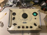
HUNTS CRB3 vintage capacitor/resistor tester
Hello,
I am selling a vintage HUNTS CRB3 capacimeter and resistor tester
Good condition, running.
220 vac
ask 120 eu. +p&p
Walter
I am selling a vintage HUNTS CRB3 capacimeter and resistor tester
Good condition, running.
220 vac
ask 120 eu. +p&p
Walter
Attachments
Thule IA60B short circuit
- By Franta2
- Solid State
- 9 Replies
My friend made some speaker cable changing, Thule amp was in standby mode. He made short circuit + and - on right side and amp is not working now.
Can you help me, where to start finding? Schematic I have...
Thank you very much for help!
Franta
Can you help me, where to start finding? Schematic I have...
Thank you very much for help!
Franta
Transmission line idea, will it work?
- Subwoofers
- 12 Replies
The important part of the design are the top two diagrams, the third can be changed. Will a 4sided transmission line work? Dotted lines represent a square brace going all around to connect the two boxes. Each brace will be hollow to allow air to move out.

Firamst build cmoy amp, output looks like a clipped triangle wave
- By magconpres
- Headphone Systems
- 3 Replies
Hi,
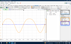
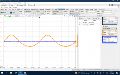
This is my first audio project, I built a CMoy amp usingthe schematic for the Crystal CMoy here: https://www.instructables.com/Crystal-cMoy-Free-Form-Headphone-Amplifier/
All seemed fine except the sound was distorted, so I hooked it up to a signal generator and o-scope.
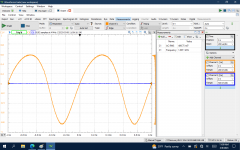
The attached images show the input 1 khz sine wave along with the output. The output is amplified, but is clipped and looks more like a triangle than a sine wave.
I did this with the amp powered from 18 vdc.
It's possible the outout is a sine wave, and it's just the scale that makes it look rather linear, but what is the likely cause ofthe clipping? Too much gain? In out too high (about 2 vdc p2p).
thanks,
James


This is my first audio project, I built a CMoy amp usingthe schematic for the Crystal CMoy here: https://www.instructables.com/Crystal-cMoy-Free-Form-Headphone-Amplifier/
All seemed fine except the sound was distorted, so I hooked it up to a signal generator and o-scope.
The attached images show the input 1 khz sine wave along with the output. The output is amplified, but is clipped and looks more like a triangle than a sine wave.
I did this with the amp powered from 18 vdc.
It's possible the outout is a sine wave, and it's just the scale that makes it look rather linear, but what is the likely cause ofthe clipping? Too much gain? In out too high (about 2 vdc p2p).
thanks,
James
Is a 60w solder iron strong enough for electronic soldering?
- By rg12
- Equipment & Tools
- 22 Replies
I need to solder and desolder some resistors and capacitors.
I have a new 60w basic solder iron, is it ok for that use? my previous
one was 30w.
I have a new 60w basic solder iron, is it ok for that use? my previous
one was 30w.
search low cost 11.2 analog pre-out ?
- By nickthevoice
- PC Based
- 1 Replies
Hi !
I search on web for low cost 11.2 CH to decoding Doldy Atmos and I don't found nothing all product is around 3'000$ and up WTF !? this is crazy why pre-amp cost now more than lots of integrated amplifier it's ridiculous !
I have my DIY amplifiers builded with LM3886 and many other project to build a 11.2 system.
Anybody have a suggestion to find a PC hi-end sound card with 11.2 analog output (but really hi-fi not I bad sound like Xonar D2X I try lots of opamp swap but never good sound)
thanks in advance for helping me 😉 !
nicK
Convenient search for electronic parts and components for DYA projects.
- By DimaSliman
- Parts
- 3 Replies
Hello friends, I know how much time can be spent searching for details for your project, so I created a search engine based on Google that currently searches 54 European, English, and American websites. It is available at the following link:
https://cse.google.com/cse?cx=f54568be26430409b#gsc.tab=0
I would be glad to receive links to stores that you use in order to expand the search engine.
https://cse.google.com/cse?cx=f54568be26430409b#gsc.tab=0
I would be glad to receive links to stores that you use in order to expand the search engine.
Dedicated Sub-Forum For Newbies ?
- By bedrock602
- The Lounge
- 84 Replies
diyAudio is such a great forum, so many knowledgeable and helpful members here. As an electronics newbie, I often feel a bit intimidated when posting a question in a forum where mostly experienced members participate in. I don't know if this is feasible but it would be nice if there were a sub-form where newbies can go to ask questions and read other newbies posts and the responses by experienced members. Threads started by experienced members geared towards newbies would also be very useful. Having all of this basic knowledge in one place would be a great asset in my opinion.
Any thoughts?
Any thoughts?
Power switcher supply AB amp with transformer for tests
- By indianajo
- Solid State
- 0 Replies
I recently purchased a used QSC CX302 amp. Switcher supply, 300 w/ch stereo, class AB. It worked okay on receipt, except the fan noise at 5 w/ch was incredibly loud. Has balanced inputs and screw terminal outputs suitable to replace the RMX850 at a church I attend with a dead B channel.
Cover off, production date was 8/10/98 and it was full of dust balls. A high mileage survivor, IMHO.
As the heat sinks are bigger than my CS800s, the fan noise I take to be a fault. I certainly won't donate it to a church that noisy and with 25 year old high mileage e-caps and fan. Perhaps one of the 3 10 k temp sensors, or more likely the e-cap parallel to it, is leaky. I can't test Q88 the temp sense transistor base to ground, it is invisible. Probably mounted under one of the 4 huge heat sinks.
If I pull the main board & daughter boards to replace these & other caps ( like the 2200 uf 200 v mains caps or the 10 470 uf 80 v miid-rail caps) the switcher supply comes out with it on the coffee table. I suggest to all that when re-e-capping, a sound check be made after every two caps to check one's (my) work. I don't want to be horsing those 200 v high energy parts right side up & upside down every 15 minutes. Nor will they probably work with a 60 w tungsten bulb in the AC feed.
What I propose is to power the mid-rails with +-47 v from a 2 amp 95 vct transformer. That transformer can reside in a nice grounded box and can be powered by the light bulb box. OEM the midrails are +-67 volts, and I see regulators that take that down to +-15, +18, +5, and other voltages much lower than +-47. (High rails are for the class H cousins with 5 times the wattage in the same box). I can leave the high energy switcher parts disconnected from the AC power feed.
I don't see a good spot to tack solder feed wires, D21 D22 D46 D47 are all under the big heat sinks. Those heat sinks have to come off to replace the invisible parts like C33, a temp sense filter cap.
It appears all control voltage feeds to the switcher supply are ahead of the final mid rail feed diodes D74 D75 D80 D81. Unless I'm wrong.
Is this a dumb way to test the boards under repair? Frequently? Has anybody else done this?
Attachments
Noisy ALPS Potentiometer
- By bedrock602
- Solid State
- 8 Replies
My preamp has a noisy ALPS volume control. The weird thing is that it is only noisy (crackly) when first powered up but after a few minutes, the noise, for the most part, goes away. I opened it up to clean it but have never seen a pot like this before.
Any suggestions would be greatly appreciated.
Any suggestions would be greatly appreciated.
Speaker Drivers Various Brands
Hello! I am trying to raise some money to support my dad, so I am selling some drivers 🙂
Here is what I have:
One pair Peerless 850544 (made in Denmark) 6.5" CSX woofer. $45 plus shipping
Single Morel ST 1108 tweeter. $307 each on Parts Express. $75 plus shipping.
One pair Mundorf amt21cm2.1-c. $445 plus shipping
One pair RCF ND 850 2.0. $495 plus shipping
Will post more ASAP
Here is what I have:
One pair Peerless 850544 (made in Denmark) 6.5" CSX woofer. $45 plus shipping
Single Morel ST 1108 tweeter. $307 each on Parts Express. $75 plus shipping.
One pair Mundorf amt21cm2.1-c. $445 plus shipping
One pair RCF ND 850 2.0. $495 plus shipping
Will post more ASAP
Randall Satan/Thrasher 50 Clean Channel Problem (LND150)
- Instruments and Amps
- 30 Replies
My friend has a Randall Satan 50 that had a completely dead clean channel. This appears to be a common problem with this amplifier and is caused by a bad LND150 in the Q2 position. I replaced the part and thought the amps was fixed, but the output is low and the signal is distorted. I think the part is damaged again.
I'm hoping I can get to the bottom of what is causing this particular MOSFET to go bad. There are two other LND150 in the amp and they don't appear to have the same problem. I replaced Q1 and it didn't make any difference. I only had 2pcs LND150, so I would like to figure out the problem before I try to source more. Please bear with my electromagical ignorance and rudimentary troubleshooting ability.
Some observations I've made for far: Q1 appears to be drawing roughly 0.5mA while Q2 is drawing 2.5mA. There is also 3.2VDC present on the gate of Q2 and only 2mV on Q1.
I'm attaching the full schematic, a pic of just the clean channel circuit, and a few scope shots. The signal is clean going in to Q1 and then gets messy.
Attachments

JBL L1 vs L3 crossover, same tweeter different crossover
Hi All,
I have a pair of JBL L1 standmount speakers and I'm looking to refresh their crossovers capacitors and change the resistors for better quality ones.
I compared the L1 crossovers to a JBL's L3 floorstanding speakers that use the same tweeters and also crossed at 3Khz (according to it's service manual) and found that for some reason the L3 crossover has "extra" resistor in paralel to the tweeter (15ohm) and different coil value (0.18mH in the L1 and 0.4mH in the L3).
As far as I understand and please correct me if I'm wrong it doesn't make any sense that 3uF+0.18mH cannot provide the same crossover point as 3uF+0.4mH, can someone please help me understand what is the crossover point for 3uF+0.18mH and 3uF+0.4mH ? JBL rate the 035TIA tweeter as 8 ohm and DCR of 3.5-4.2 ohm.
1. what are the actual calculated crossover points of the L1 and L3?
2. What is the purpose and effect of the "extra" 15 ohm resistor in parallel to the tweeter on the L3?
And.....I cannot find any branded 3uF capacitor to replace the original one, only 3.3uF, How using a 3.3uF capacitor instead of 3uF affects the crossover point considering it's 10% "extra" capacitance.
Thanks
Paper cone reinforcement
- By noviygera
- Construction Tips
- 9 Replies
How do you guys recommend to reinforce a crease in the edge of a 8" paper cone, where the cone lost it's rigidity?
1. Wood glue + thin paper on the back side?
2. thin layer of epoxy?
3. other???
1. Wood glue + thin paper on the back side?
2. thin layer of epoxy?
3. other???
Affordable shunt caps?
- Multi-Way
- 24 Replies
I am currently looking for caps of around 250-300 uF for shunting a woofer.
Was planning to use Jantzen CrossCap, but are their any more affordable brands out there to look at?
Was planning to use Jantzen CrossCap, but are their any more affordable brands out there to look at?
For Sale Mundorf AMT21CM2.1-C Tweeter Pair
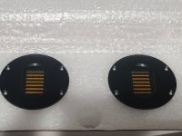
I'd like to get $475 for these plus shipping and/or fees. Open to offers. They're on Madisound right now for $534 each, ($1,068 per pair!)
Thanks 🙂
Thanks 🙂
Attachments
Musical Fidelity X10-D blowing capacitor C8
- By Barry NJ
- Tubes / Valves
- 14 Replies
I have a Musical Fidelity X10-D that is blowing capacitor C8. The unit became noisy, so I took a look and noted that C8 was swollen at the top. I replaced it and C4 for good measure, and the new one did the same after a day. So now I'm figuring there is an issue elsewhere, causing this problem with the capacitor in C8 position, but I'm not sure what I should be checking(?) Any guidance is appreciated.

2023-02-08_08-04-10 by Barry, on Flickr
2023-02-08_08-04-10 by Barry, on Flickr
Question about BF245B
- By franziscko
- Parts
- 45 Replies
Hi everyone.
Please help me because I have a big problem.
I have several jfets like this, I need to build a simple preamp
for guitar and I don't know the correct pin arrangement.
I've tried several times but nothing sounds. Now I fear I have them
damaged all. Can you help me? Is the acronym PH Philips?
Thank you!
Genelec S30 LF driver, different versions?
Hello,
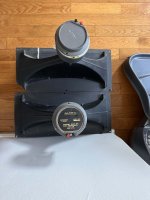
I have 5 pieces of Genelec S30 or S30 NF on my workbench right now to be refurbished.
Electronics basically works, but all midrange drivers (Peerless KO40MRF) and one LF driver have rotten surrounds.
Surrounds for the midrange are easily available, regarding the woofer I post here:
Total I have found in the 5 pieces S30, 3 different woofer types:
Peerless Cat. No.:
830298
831346
and 1x unbranded, looks identical to 830298
The drivers with number 830298 are fine, have a rubber surround. 831346 had a foam surround which has crumbled with age.
Does anyone know if different woofers were simply used during the production period?
I would like to compare the TS parameters and then decide from which side I approach the repair. Does anyone have datasheets? Couldn't find anything in the internet unfortunately.
At the end the speakers should sound as identical as possible. Maybe it makes sense to get a used woofer (with rubber surround) instead of repairing the one with the rotten foam surround, if the parameters differ too much. Drivers look almost the same, but I can not exclude that someone has tinkered around althought the speakers have been in broadcast duty all there life and the technicians there normaly knwo what they are doing
Have contacted the Genelec support, but they stopped support and so far refused to provide any data...
Any help appreciated!
best,
Georg
A simple and effective HV supply
- By Elvee
- Power Supplies
- 14 Replies
This supply is derived from my ion-chamber project:
https://www.diyaudio.com/community/...ve-this-electronic-filter.395321/post-7256296
Since it has little relevance to audio, I am not going to document it in its entirety, but the supply section could be of some use.
It is a low-power bias source, that could be used in an ESL, electrostatic headphones, special condenser microphones, etc. In my case, it is set at 4.7kV, the optimum for the geometry of my chamber, but it is adjustable from ~3 to 9kV, and the circuit can easily be adapted for practically any other voltage range.
Its current consumption is low enough to allow battery operation, and the output is remarkably clean, without using large filter caps thanks to an electronic filter. At a supply voltage of 7.5V, the consumption of the HV section alone is ~10mA, rising to ~16mA with the filter.
Although it is designed for static bias only, it can deliver a non-negligible current too: when I connect a 100 megohm test probe at the output, the regulation absorbs the supplement, and the current consumption rises to ~50mA.
Here is the circuit:

And here is how it looks like physically:

It is essentially a flyback converter, followed by a voltage tripler.
I will discuss the circuit and the components in the next post
https://www.diyaudio.com/community/...ve-this-electronic-filter.395321/post-7256296
Since it has little relevance to audio, I am not going to document it in its entirety, but the supply section could be of some use.
It is a low-power bias source, that could be used in an ESL, electrostatic headphones, special condenser microphones, etc. In my case, it is set at 4.7kV, the optimum for the geometry of my chamber, but it is adjustable from ~3 to 9kV, and the circuit can easily be adapted for practically any other voltage range.
Its current consumption is low enough to allow battery operation, and the output is remarkably clean, without using large filter caps thanks to an electronic filter. At a supply voltage of 7.5V, the consumption of the HV section alone is ~10mA, rising to ~16mA with the filter.
Although it is designed for static bias only, it can deliver a non-negligible current too: when I connect a 100 megohm test probe at the output, the regulation absorbs the supplement, and the current consumption rises to ~50mA.
Here is the circuit:
And here is how it looks like physically:
It is essentially a flyback converter, followed by a voltage tripler.
I will discuss the circuit and the components in the next post
Cheers to diyAudio
- By von Ah
- The Lounge
- 14 Replies
I’m raising my glass to diyAudio.com for all the enjoyment it has provided me for more than 14 years. A SAFE place to realize this hobby in a way that would not be possible in its absence. What a gift, especially in the last few years. I’ve been able to take my music enjoyment to multiple advanced levels because of this forum and I am forever grateful. There are MANY people here that have given immeasurable time and effort to spreading the wealth of true do-it-yourself audio. THANK YOU.

Passive Filter for Class D Amp Testing - built
- By PWatts
- Equipment & Tools
- 7 Replies
For those who may be curious, I simulated and built this 20kHz brickwall filter in a little case. Parts were series/paralleled and inductors unwound to get close to exact values.
I quickly tested it and it seems pretty good, better than the earlier RC based one I used.
(original thread closed but here)
https://www.diyaudio.com/community/...r-for-class-d-amp-testing.277076/post-4390598
I quickly tested it and it seems pretty good, better than the earlier RC based one I used.
(original thread closed but here)
https://www.diyaudio.com/community/...r-for-class-d-amp-testing.277076/post-4390598
Attachments
Any idea to improve this electronic filter?
- By Elvee
- Power Supplies
- 97 Replies
I am building a HV (5kV) supply to bias an ionization chamber.
The supply needs to be clean, both from the converter ripple and the external electrostatic influences.
The logical solution would be a large bypass cap, but at 5kV, it is unpractical.
I plan to use 1.5nF caps, and multiply their effect using an active circuit.
This circuit works:

But I wonder if simple improvements are possible, without going overboard, compromising the stability or using insane components values.
Any ideas?
The supply needs to be clean, both from the converter ripple and the external electrostatic influences.
The logical solution would be a large bypass cap, but at 5kV, it is unpractical.
I plan to use 1.5nF caps, and multiply their effect using an active circuit.
This circuit works:
But I wonder if simple improvements are possible, without going overboard, compromising the stability or using insane components values.
Any ideas?
Has anybody here handsoldered TSSOP?
- By SonocusEric
- Parts
- 11 Replies
So i ended up ordering tssop package opa1655 by mistake and now i have a whole reel of them that im stuck with.
Im thinking of drawing up a pcb for them but not sure its practical to try to solder them by hand.
What do you guys think?
And also do tssop and soic parts perform the same?
Im thinking of drawing up a pcb for them but not sure its practical to try to solder them by hand.
What do you guys think?
And also do tssop and soic parts perform the same?
OPA134
- By Chrisr3521
- Swap Meet
- 5 Replies
Hi looking for 2x opa134 opamps, anyone have any they could part with?
Remote (AXD7746) for Pioneer SX-N30AE
- By trecords
- Solid State
- 0 Replies
Hello, can someone offer me remote for Pioneer SX-N30, its original remote is AXD7746, AXD7747. I cant find any in ebay((
I dont want to use AXD7660 which is somthing pioneer universal becouse it is ergonomically not nice, it could be only last option for me.
Regards.
I dont want to use AXD7660 which is somthing pioneer universal becouse it is ergonomically not nice, it could be only last option for me.
Regards.
WTB First Watt F3 boards/parts
- Swap Meet
- 2 Replies
Hi, I'd like to try building a First Watt F3 clone and wondered if anyone had any spare boards and/or parts sitting unused in a cupboard they would like to move on? I know I'm guilty of that and assume others are as well! Many thanks. David Whistance
Kenwood KR 4200 Relay issue
- By hifisucks
- Solid State
- 39 Replies
Hello, I have a 4200 and have falling out channels... after cleaning the relais contacts it works for maybe 1 or 2 days... then the same...
I have already looked for one but cant find a substitute... its 24V...
Somebody firm in this matter?
Christoph
I have already looked for one but cant find a substitute... its 24V...
Somebody firm in this matter?
Christoph
Fostex FE168e∑ in Onken. Has anyone tried?
- By perkri
- Full Range
- 18 Replies
Hi,
Recently picked up a pair of FE168Ez. Thinking of trying them out in a couple of different enclosures.
Looking at a BiB, a basic Voigt Pipe and an Onken.
MH-Audio has a calculator for the Onken, wonder what luck folks have had using it to arrive at a design?
The specs on the FE168Ez seem to lend themselves to an Onken build based on the calculator.
Any thoughts would be greatly appreciated!
Per
Why do I like low powered amps so much?
- By cracked case
- Solid State
- 180 Replies
I started my foray into diy audio tinckering with TDA2822 chip amps, then progressed, including a NAD 3020 saved from a skip, then an Onkyo and a TPA3116 based amp, but when my 3116 developed a fault, I went back to a PAM 8403 based amp that I had made earlier; and very nice it sounded to, so now I've made one based on a PAM 8406, and it's sound is quite remarkable. I'd say better than anything else that I've heard (not that I've heard much), especially the timbre of instruments.. But the thing is, WHY do I like the sound so much, they have terrible distortion.
So I have come up with the following possibilities -
I like the distortion
DNM amps have very little metal in their construction, something to do with eddy currents, is there something in this (there is very little metal in my current PAM amp)?
They have very low noise floor
They don't need so many amplification stages, meaning less distortion; but why can't this be measured if it's a different distortion to the one quoted?
They give a surprisingly good sound for what they are, just like a small speaker might give surprising bass for it's size, even though it might not be particularly good, the fact that is comes from a small speaker gives it a bias in it's favour.
There's some advantage in using a 5 volt supply instead of something like 40 volts duel rail, because there's less resistance in the circuit.
These are just some random guesses, I just can't get my head around an amp with such bad measured performance, sounding so good, if you have any ideas, or you think I must have cloth ears or something, please let me know.
50 Watt Per Channel EL34 Ultra Linear Amplifier.
- By miker500
- Tubes / Valves
- 1 Replies
Has anyone ever built this amp??
https://www.angelfire.com/electronic/funwithtubes/Amp-EL34_UL.html
https://www.angelfire.com/electronic/funwithtubes/Amp-EL34_UL.html
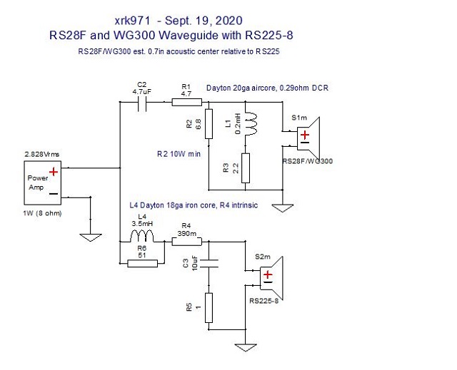
Passive XO for Time-Aligned RS225-8 and RS28F in Waveguide
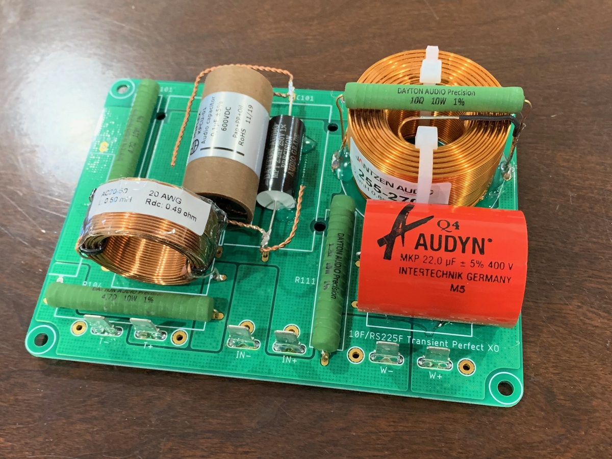
I have been using the RS225-8 for years in a 2-way FAST with a full range for a tweeter. Recently, I have been using an RS28F in a Monacor WG300 waveguide with a Purifi PTT6.5 TL speaker with great success. Since I already have FRD and ZMA files handy for these drivers I wondered how well the combo of the RS225-8 and the RS28F in a WG300 would work out together. A very quick simulation in Xsim seemed to yield pretty good results. Although the RS28F is no longer available, I have tested the RST28F in the same waveguide and it measures very close - allowing for similar performance. The crossover is based on the assumption of a certain acoustical delay which I have not been able to measure yet, but estimated based on the positions of the voice coils on a baffle and the depth of the waveguide. The crossover I came up with is strange in that it has a deep notch if invert the polarity of the tweeter and sums up fine if left normal. Not sure why this is.
Schematic for crossover with 1.5kHz crossover frequency:
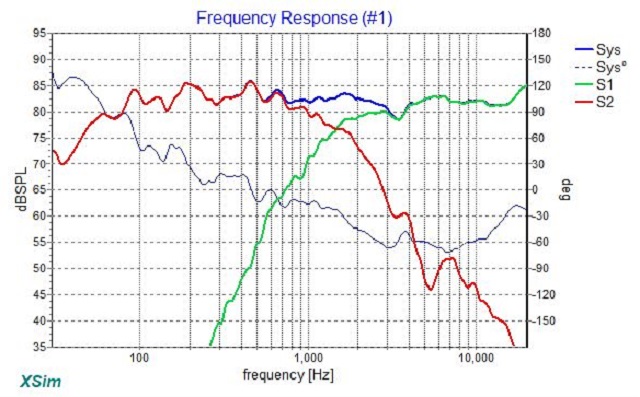
Predicted frequency response (if we mount this in a TL, the bass below 100Hz will extend to 30Hz):
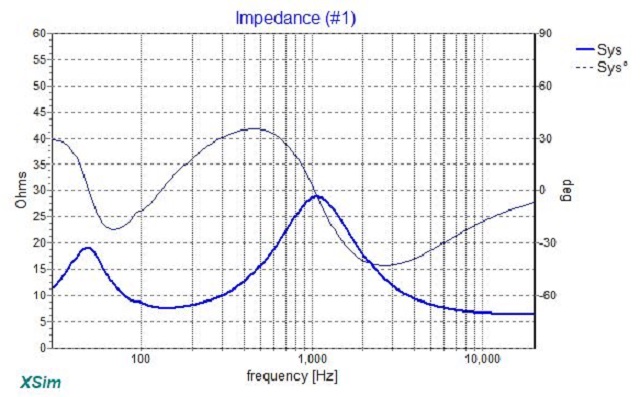
Predicted impedance curve (min ~6ohms):
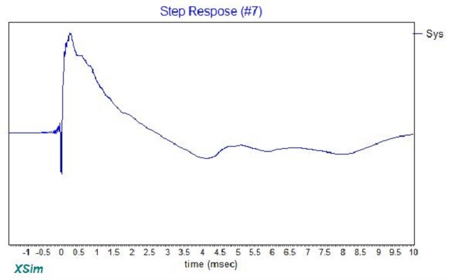
Predicted step response showing great time alignment:
Next step is to make a test baffle and measure in-situ. Is this worth a try and what do you guys think about the polar integration between an 8in driver and 7in waveguide if XO is at 1.5kHz?
One other nice thing about this XO design is that it would fit perfectly into my existing passive XO PCB which has been used for both of the speakers mentioned above, and would look something like this:
Schematic for crossover with 1.5kHz crossover frequency:
Predicted frequency response (if we mount this in a TL, the bass below 100Hz will extend to 30Hz):
Predicted impedance curve (min ~6ohms):
Predicted step response showing great time alignment:
Next step is to make a test baffle and measure in-situ. Is this worth a try and what do you guys think about the polar integration between an 8in driver and 7in waveguide if XO is at 1.5kHz?
One other nice thing about this XO design is that it would fit perfectly into my existing passive XO PCB which has been used for both of the speakers mentioned above, and would look something like this:
cd tray won't open, Yamaha CRX-E150
- By gychang
- Digital Source
- 5 Replies
I noticed the cd tray will not open at all when I first got the unit, looked inside and there was a broken rubber band, I replaced the band now it will not open unless I click on the "open" switch first and quickly give a little push on the tray faceplate as seen on the video.
Yamaha CRX-E150 cd tray won't open - YouTube
what is the likely cause?, shall I tray a little larger band? I am a novice as far as electronic but can try to replace the band...
Yamaha CRX-E150 cd tray won't open - YouTube
what is the likely cause?, shall I tray a little larger band? I am a novice as far as electronic but can try to replace the band...
Attachments
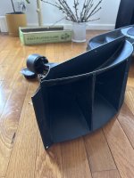
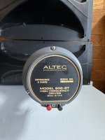
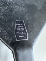
For Sale Altec A7 Speaker Parts for sale
- Swap Meet
- 4 Replies
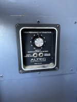
2x Altec 511b horns (one has a chip in a corner)
2x Altec 802-8T Compression Drivers 8ohm
2x Altec 421-8H Woofer 8ohm
2x Altec N809-8A Crossover
I do not have cabinets for sale. For sale as package or spare. Pickup in Brooklyn NY 11211 or can arrange shipping.
$1500 for the whole lot.
2x Altec 802-8T Compression Drivers 8ohm
2x Altec 421-8H Woofer 8ohm
2x Altec N809-8A Crossover
I do not have cabinets for sale. For sale as package or spare. Pickup in Brooklyn NY 11211 or can arrange shipping.
$1500 for the whole lot.
Attachments

Need help with ML-9
- By miranda84
- Solid State
- 2 Replies
Hi y'all!
I'm trying to understand a problem with my ML-9 amp + renaissance 90 speakers.
Yesterday, at about 40% of max volume the music system suddenly stopped and I noticed that the ML-9 has switched itself off - the power button was in OFF position. When I try to switch it on, it switches off immediately.
How can I determine if this is a small problem, maybe I need to change a fuse or a more serious issue?
Thank you in advance 🙂
Miranda
New Issue Magnifying menu on smartphone
- By lcsaszar
- Forum Problems & Feedback
- 2 Replies
Old-new problem: when the two-finger gesture for magnifying the screen is applied, the menu items go off screen.
Desired behavior: the left edge of the menu should be anchored.
And perhaps clicking on the menu items should expand them, not only the down arrows on the right (that go offscreen when magnifying).
Desired behavior: the left edge of the menu should be anchored.
And perhaps clicking on the menu items should expand them, not only the down arrows on the right (that go offscreen when magnifying).
looking for feedback on higher Qtc
- By neurotopia
- Multi-Way
- 11 Replies
I’m looking for feedback from anyone who might have some real-world experience with:
1) The Morel MW166 (6”)
2) And higher Qtc sealed speaker performance
I’m putting together a sealed (not interested in ports) 2-way MTM using the MW166, but it’s got a pretty high Qts, right off the bat. Putting it into a 30ish litre box would put it at around 0.9Qtc. I’ve built a number of speakers but never any with Qtc > 0.7. So I don’t know firsthand what a higher Qtc sound like. Since it’s a 2-way design (paired with a ScanSpeak Classic D2905/9500), the Morels will be tackling both mids and lows (xover around 2000Hz). So transient response will be important. Is a 0.9Qtc going to be able to keep up on more complex passages or will I lose a lot of detail? I also won’t be blasting them, since it’s a home hi-fi application (i.e. never more than 50 watts and likely not even that).
My second question pertains to the Morel driver, itself. I’ve read through some posts that were not positive regarding Morel drivers. And I’m certainly open to alternatives. I can tell by the SPL graphs that I will be crossing the Morel over past its break-up point but just haven’t seen anything that better suites my need in terms of frequency response range.
Thanks!
TDA7293 DC-offset
- Chip Amps
- 4 Replies
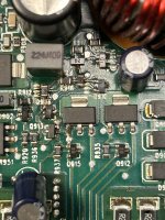
Hey people,
some days ago I built two chipamps with TDA7293 chips (laser engraved, measure pin5, 10 & 11 against backplate all 3,xx MOhm, they seem authentic). I used dual-pcbs made by JLCPCB, but put just one chip on. Parts are nothing special, just what I had lying around. Input caps are 4.7µF WIMA MKS and the other one has 2x 1.5µF epoxy-coated recycling ware 😉. Just for curiosity I measured the DC-offset. Therefor I shortened the input, no speaker, Multimeter "Kaiweets KM601" at 3 digits right of the comma, and put +/-27V DC in it. It measured 0,000 for both amps. Am I making a mistake, or is there really no, for me, measurable offset?
best regards
Jochen
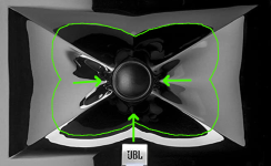
Image control waveguide vs rectangular waveguide?
- Multi-Way
- 5 Replies
Can anyone tell me how the image control waveguide improves on a standard rectangular waveguide?
Forgive me if this has been discussed elsewhere. I did see a 2018 patent which describes this feature as "clover like," but did not understand the patent. I do understand that the function of the waveguide is primarily to reduce dispersion at low frequencies to better match the directivity of the HF driver to the LF driver.
Forgive me if this has been discussed elsewhere. I did see a 2018 patent which describes this feature as "clover like," but did not understand the patent. I do understand that the function of the waveguide is primarily to reduce dispersion at low frequencies to better match the directivity of the HF driver to the LF driver.
Attachments
Podium 1 planar repair
- By GipsyRacer
- Planars & Exotics
- 5 Replies
I am lucky enough to be the owner of a pair of early Podium Sound 1 speakers. I've had them for over 10 years of light use. Unfortunately, one speaker has developed a fault, which manifests itself as a buzzing/rattling at about 40 Hz, or when the panel is played at high volume. Just one panel is affected.
Using an endoscope to view from the rear, the problem appears to be quite obvious. The bottom driver has a cup and socket arrangement, whereby the male part is bonded to the panel and the female is a receiver which looks like its attached to the voice coil.
Traces of the original failed adhesive joint can clearly be seen. There is sufficient (careful) deflection in the panel to expose the whole of the failed glued joint. It looks like it should be possible to re-glue using a syringe.
So the questions are:-
1) Has anybody else tried to execute a similar repair from which I might learn or avoid pitfalls?
2) What sort of glue to use? I will probably only get one shot at this.
3) Does anybody know which drivers are used, in case I need to get hold of some replacements?
I should add that I contacted the current owners of the Podium operation and received a reply from David Katz offering me a discount on some new speakers, but no advice on how to fix my old ones or help to find out where I might procure a replacement driver.
All wisdom appreciated!
Tubelab SSE part numbers
- By CrtrTV
- Tubes / Valves
- 29 Replies
Dear all,
Having bought an SSE board (and transformers) years ago, I now want to go ahead and build this. In looking up the parts on mouser/digikey it appears that many of the part numbers are obsolete, or parts discontinued. Do any of you recent builders have a list of current part numbers you could share with me? I am UK based.
Thanks in advance...
WinISD Pro Alpha Peaking 2nd order highpass and DSP
- By wdyn1
- Digital Line Level
- 0 Replies
In WinISD Pro Alpha there is a filter called "Peaking 2nd order highpass". I'm working on a design that uses the "ESB3 extended bass shelf -3dB" option for the box. When properly set, the peaking 2nd order highpass nearly perfectly corrects the -3dB shelf and cuts off any extremes at the low end of the spectrum. However, I can't find any information about what exactly is going on with that filter or how to implement it. So...
-- What is the "Peaking 2nd order highpass" and how do I implement it in DSP?
-- What is the "Peaking 2nd order highpass" and how do I implement it in DSP?
MP3 decoder board
Can someone help me please I just installed the decoeder board into my car, i connected the speaker outputs from the decorder board to the Aux input on the cars head unit. Im getting alot of crackling coming through the speakers there is no humming noise. i used the cigaret lighter socket live and ground to power the decorder board as this is fed by the cars acessory circuit. on the decorder board the left and right speaker outputs have positive and common wires i only connected one common wire as my Aux input only has one common connection. how can i stop this crackling noise
many thanks in advance Ps if i connect the two commons together on the decorder board there is no sound output this is why i only connected one and not join them together
many thanks in advance Ps if i connect the two commons together on the decorder board there is no sound output this is why i only connected one and not join them together
Plate to plate hum
- By Miniwatt
- Tubes / Valves
- 39 Replies
LS.

I’ve been happily building this and it sounds great, but it has a little bit of hum and I can’t get rid of it, it must be something I don’t know/understand yet.
The basic idea is a self-splitting output stage with plate to plate feedback from the driver.
At first I just directly grounded the grid of the bottom 6550, only resistor the gridstopper. Hummed. Added the 220K ground leak. Same result.
Added the feedback resistor and cap as in the schematic. Still hum.
Spent lots of time looking for ground loops, no result.
Key thing is: the amp is dead quiet with the feedback resistor disconnected.
What am I missing?
Thanks in advance.
Top Mastering Engineer Bernie Grundman is talking about Vinyl.
- By plasnu
- Analogue Source
- 0 Replies
Top Mastering Engineer Bernie Grundman is talking about Vinyl. Long video but very insightful.
Login to view embedded media
Login to view embedded media
MTX Thunder 4405
- By Fosgate2001
- Car Audio
- 1 Replies
I just bought this amp from a buddy he said it powered up but had no sound .
When I opened it up I noticed a lot of burnt resistors .
Wondering does anyone have the values of these resistors or have a picture of this area ?
When I opened it up I noticed a lot of burnt resistors .
Wondering does anyone have the values of these resistors or have a picture of this area ?
Attachments
WTB WTB: KSC5026MOS/STN9360/IXCP10M90S
Am waiting on these back ordered parts to build a KGSSHV, might as well try my luck here while waiting in case someone has spare ones to get rid of.
I need at least:
Thanks 🙂
I need at least:
4 x STN9360- 3 x IXCP10M90S (TO220)
4 x KSC5026M
Thanks 🙂
DIGITECH 2120 Firmware v2.30
- By snapper
- Instruments and Amps
- 0 Replies
Hi, i'm looking for the firmware v2.30 update for some valve guitar system i desire to update:
DIGITECH 2120 Firmware v2.30
(the eprom file / firmware would be enough for me)
THX

DIGITECH 2120 Firmware v2.30
(the eprom file / firmware would be enough for me)
THX
TDA1543 - one per channel in a NOS DAC?
- By dadix4e
- Digital Line Level
- 3 Replies
Hello .
I know that the tda1543 chip is stereo, but I'm interested if someone has tried to make a construction in which only one is used for one channel (in NOS mode) and the other for another channel (also in NOS mode) . If so, what conclusion did he reach? Are there data that have been measured?
in theory, the stereo separation should be better. And if there were several linked in parallel keeping the same construction, what results would be reached? I recently bought a Lite DAC-AH that works NOS and has 8 tda1543 chips connected in parallel. That's how I read, I'm not an electronics expert.
Show Us Your VeroRoute Project
- By fubar3
- Construction Tips
- 3 Replies
I have been sending simple Kicad Gerbers off to a Fab and receiving good PCBs. However, sometimes I change my mind while the Fab is working so I must hack the received PCBs. When searching for the latest KiCad on Ubuntu Linux, the response included VeroRoute which I also installed. After a quick read of the tutorials, it looks pretty good. So I am wondering if VeroRoute would be a valuable add to my toolkit for simple layouts.
Is SSE board toast?
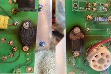
This goes along with my "SSE trouble" post. Another post from 2019 titled “Tubelab SSE blown C12 and R17 should I replace board” asked if their board was too burnt to reuse after R17 fried. It showed minor scuffing to the board. George mentioned if it’s brown it should be ok, but black causes issues with higher voltages. Well, how about this PC board burn spot, picture attached. Is the board toast? It’s under R17 where only about 50V runs. Do I need a new board?
Attachments
Finally completed something! Millett SSMH 12AU7
- By Fast14riot
- Headphone Systems
- 0 Replies
Picked up this 12au7 version of the Millett Starving Student hybrid headphone amp over 10 years ago from a guy in Australia that had a run done for himself and sold the others for cost. Finally decided to build it and ordered everything on the BOM except a case.
Well, as a total noob, it has taken me several weeks and ordering other things I found out I needed as I went along. First it was needing hookup wire. Then it was XH plugs, but I didn't know I needed a specific crimp tool to use those plugs, and ordered that too. Then trying to find build info for a one off production run from a decade ago has been hit or miss. Then, I realized that 18awg hookup wire is too big for XH connectors and needed to order 24awg, too. Got right to the end and found out I didn't have mounting hardware for the mosfets to the heat sinks. Run to the hardware store for that.
I didn't have any thermal paste, so I didn't let it run too long, maybe just a few minutes and the heat sinks were getting warm. But, everything functioned as it should! Now, to build a case for it.
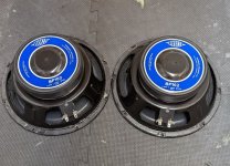
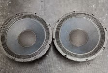
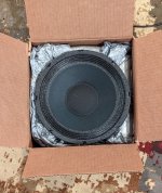
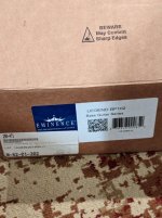
SB 29R Ring Radiator Tweeters
Great conditions one soldered, one was not soldered. with original boxes. $69 Pair plus shipping


Recently began get Oops! messages
- By GM
- Forum Problems & Feedback
- 31 Replies
........when clicking on 'attached' stuff and/or loading thread page with one and FWIW I found apparently all forums/threads on Hostboard missing, so wondering if my computer's infected and AVAST isn't protecting me.
https://www.diyaudio.com/community/...64:~:text=503 Service Temporarily Unavailable
https://www.diyaudio.com/community/...64:~:text=503 Service Temporarily Unavailable
CE1000 Chassis + Transformer
- By garboui
- Solid State
- 1 Replies
I have a CE1000 that's been sitting in a closet. It has been through a cycle of repair, getting blown up (op trans and something in protection cct is bad) again and then stored for lack of will for repair. I do not intend on trying to fix this again (partly out of the time investment) as I am slowly transitioning to class d amps (watching 100's of watts being blown away for nothing saddens me). The transformer in this amp is a beast and the main rails supply +/- 60V. Are there any decent class d amp boards that I could retro fit in here (after adding the required rectification and filtering)? I would prefer low noise over power.
Cheers
Cheers
Toroidal Transformers, HackerCap PSU PCBs, HAWK A18 amplifier PCBs
- By delfimmarues
- Swap Meet
- 7 Replies
2 Canterbury Windings Transformers, purchased for Avondale Amplifier - Qudos, that have never been used or assembled due to their oversized size.
Type no: TM1201B
Power rating: 500VA
Primary: 0-230V @ 50Hz
Electrostatic screen
Secondaries: 35-0-35V @ 7,14A rms
GOSS band
Regulation: 4%
Dimensions: 162mm diameter away from leadouts x 60mm high
Weight: 5,7 Kg
Mounting: M8 insert in a potted centre
Leadouts: 200mm long flexible (stranded)
Audio grade construction
Original Price: £ 105,60
Price € 80,00
One 100 VA Holden & Fischer Toroidal Transformers Removed from a fully functioning Cyrus One amplifier
120/220 / 240v primary
23.5v - 0 - 23.5v secondary
Price € 30,00
One Noratel Toiroidal taken from Naim NNT001, I don't know the power
Prim. 2X 115V
Sec1.13v - 0v - 13v
Sec2 12v - 0v - 12v
Sec3 9.6v - 0v - 9.6v
Price € 30,00
Send pm for additional information or calculate shipping costs
4 PCB for the HAWK A18 amplifier, € 7,50 each
8 HackerCap PSU PCBs, € 7,50 each
Items never used or assembled with a shipping cost of € 4.65 in an express padded envelope.
Thanks: D
Type no: TM1201B
Power rating: 500VA
Primary: 0-230V @ 50Hz
Electrostatic screen
Secondaries: 35-0-35V @ 7,14A rms
GOSS band
Regulation: 4%
Dimensions: 162mm diameter away from leadouts x 60mm high
Weight: 5,7 Kg
Mounting: M8 insert in a potted centre
Leadouts: 200mm long flexible (stranded)
Audio grade construction
Original Price: £ 105,60
Price € 80,00
An externally hosted image should be here but it was not working when we last tested it.
An externally hosted image should be here but it was not working when we last tested it.
One 100 VA Holden & Fischer Toroidal Transformers Removed from a fully functioning Cyrus One amplifier
120/220 / 240v primary
23.5v - 0 - 23.5v secondary
Price € 30,00
An externally hosted image should be here but it was not working when we last tested it.
An externally hosted image should be here but it was not working when we last tested it.
One Noratel Toiroidal taken from Naim NNT001, I don't know the power
Prim. 2X 115V
Sec1.13v - 0v - 13v
Sec2 12v - 0v - 12v
Sec3 9.6v - 0v - 9.6v
Price € 30,00
An externally hosted image should be here but it was not working when we last tested it.
An externally hosted image should be here but it was not working when we last tested it.
An externally hosted image should be here but it was not working when we last tested it.
Send pm for additional information or calculate shipping costs
4 PCB for the HAWK A18 amplifier, € 7,50 each
An externally hosted image should be here but it was not working when we last tested it.
8 HackerCap PSU PCBs, € 7,50 each
An externally hosted image should be here but it was not working when we last tested it.
Items never used or assembled with a shipping cost of € 4.65 in an express padded envelope.
Thanks: D
For Sale BPA300 300W Dual Mono Blocks Chip Amplifier assembled kit with all parts (incl. 12 LM3886T chips)
For Sale, BPA300 300W Dual Mono Blocks Chip Amplifier assembled kit with all parts (incl. 12 LM3886T chips)
This kit is to build a pair of 300W monoblocks using bridged LM3886T Chipamp module and DRV134 SE-Balanced drivers. The idea was to have two 150W amp module made of three bridged LM3886T, driven in opposite polarity by a DRV134 converter card, that splits the Single Ended RCA amp input in Phase+ and Phase- signals that drive the 150W. So you have two 150W bridged POS and NEG, giving you a huge 300W output.
I made my one DRV134 interface card with two DRV134, making it a stereo input module, because I was planning to build a stereo amp, not a pair of monoblock.
But I have all the part and PCB to build an extra stereo DRV134 card, so you can use one in each monoblocks, just use one side of each pcb.
Each DRV134 interface PCB has local +/-15V supplies, with CRC pre-filter, and optional drop resistor depending on the amp supply, so this small interface is running directly from the main amp supply.
The kit inludes 4x 150W amp modules with professional made PCB and very high quality parts (Mundorf cap, Vishay WSR-3 resistors, etc) and one assembled DRV134, one extra DRV134 bare pcb and parts to assemble. Can't find the DRV134 chip, you'll need to buy them, but they are easy to source from Mouser or Digikey... The Amp modules are pre-assembled by me, very good soldering, made to last.
All parts are original bought from Mouser and Digikey at the time. Project article, full schematic and BOM included with the sale.
The monblock amp assembled pictured are for reference only.
To complete the project you need to buy the DRV134 chips and the amp +/-30 power supply (transfo, rectifier, caps), stereo or monoblock configuration, you choice...
The kit has 12 LM3886T chip s in total, the last pair of original LM3886T I bought this year, from Germany costed me 56$...
Keep in mind that the LM3886T is now difficult to source as well...
Great kit, but need to reduce my projects. sorry to let this one go. Your chance for a great kit...
Asking 300U$ o.b.o + shipping + 3.5% Paypal fee
Thanks for looking
SB
Attachments
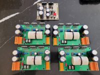
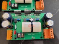
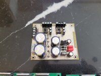
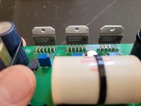
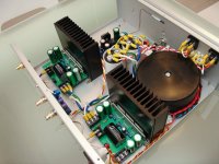
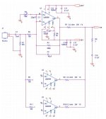
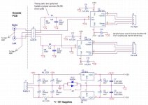
A $1 million Listening Room Project, revisited.
- The Lounge
- 8 Replies
https://futureaudiophile.com/univer...phile-experience-to-its-students-and-you-too/
BTW, the article contains the email address to request an appointment to have a listen, if you are in or traveling in the area!!!
amb,
john
Metallic spiders for high Qms drivers?
Has anyone or any company ever considered using a metallic spider to reduce mechanical losses, and create high qms drivers?
Although this may only really be applicable to high suspension stiffness low Xmax drivers, would it be possible to use a metallic flexure in place of a regular spider, to avoid viscoelastic losses associated with polymer based solutions? As metals have very very low tan delta coefficients (viscoelastic loss). I'm not completely sure if it would be of much benefit other than allowing lower Qes values for the same Qts but its likely marginal.
Although this may only really be applicable to high suspension stiffness low Xmax drivers, would it be possible to use a metallic flexure in place of a regular spider, to avoid viscoelastic losses associated with polymer based solutions? As metals have very very low tan delta coefficients (viscoelastic loss). I'm not completely sure if it would be of much benefit other than allowing lower Qes values for the same Qts but its likely marginal.
Attachments
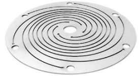
Another “Want to use TO-264 in place of MT-200” thread, opinions wanted. Side note, looking for lateral mosfets.
- By saabracer23
- Parts
- 3 Replies
Awhile back I had a thread asking opinions on replacing the outputs in a Yamaha amplifier. It used 2SA1169 and 2SC2773 and it was concluded that MJL1302 and MJL3281 would make a good replacement despite having less overall surface area in contact with the heatsink. The MJL devices having higher dissipation, voltage and current capabilities. Well that Yamaha (R-1000) used one pair per channel and it’s been running every day for 3/4 of a year without issue.
Well I’m in the same boat, but this amp uses even lower power capable outputs, so I don’t see why this wouldn’t work, though there are many more packed onto the heatsink, and it’s a much nicer amp.
It’s a Kyrocera A-910 and each channel of the amp uses three 2SA1215 and three 2SC2921. Unfortunately the outputs are not too healthy.


One had the front of the case blown off of it. Both channels each have one NPN and one PNP that are good, the rest are either shorted, open, or measure as a diode on a Peak Atlas DCA75. The plan was to buy enough to replace all 12 from B+D enterprises, but when I went to purchase 12 of each I found that they only have
2 of one and 5 of the other. So sadly not an option. So my thoughts are to drill and tap new holes in the heatsink for the MJL devices, thoughts?
Secondly, it looks like they’re being driven by a pair mosfets, 2SK214 and 2SJ77. Is there anything that will work here? Or if they die I basically have a very heavy paperweight? It would be sad for something so nice and powerful to be taken down by tiny TO-220 devices. I measured once channel and they measure okay, but haven’t done the other. Thought I should plan just in case the mosfets in the other channel were taken out when the outputs died.

Dan
Well I’m in the same boat, but this amp uses even lower power capable outputs, so I don’t see why this wouldn’t work, though there are many more packed onto the heatsink, and it’s a much nicer amp.
It’s a Kyrocera A-910 and each channel of the amp uses three 2SA1215 and three 2SC2921. Unfortunately the outputs are not too healthy.
One had the front of the case blown off of it. Both channels each have one NPN and one PNP that are good, the rest are either shorted, open, or measure as a diode on a Peak Atlas DCA75. The plan was to buy enough to replace all 12 from B+D enterprises, but when I went to purchase 12 of each I found that they only have
2 of one and 5 of the other. So sadly not an option. So my thoughts are to drill and tap new holes in the heatsink for the MJL devices, thoughts?
Secondly, it looks like they’re being driven by a pair mosfets, 2SK214 and 2SJ77. Is there anything that will work here? Or if they die I basically have a very heavy paperweight? It would be sad for something so nice and powerful to be taken down by tiny TO-220 devices. I measured once channel and they measure okay, but haven’t done the other. Thought I should plan just in case the mosfets in the other channel were taken out when the outputs died.
Dan
Counterpoint NP Mono Problems - Member CVANC Please let me know how I can buy one of your schematics
Hello All,
I am fairly new to this site and still cannot PM anyone on this site. I am looking for schematics for Counterpoint Natural Progression Mono 150 watt amplifier. I see member CVANC might have schematics and/or operator's manual but this site will not allow me to start any communication with any members.
Also, hopefully someone may have a solution to my problem with both amps. They severely output a 60 Hz signal to speakers when in standby or warmup mode (not ground loop from A/C power source). When warmed up (LED lit blue), the 60 Hz decreases (still faintly audible) but the output signal is low to the speakers with the preamp volume set to high. One amp is distorted, the other amp just has a low output. After a few minutes of being in the "Operate" mode, it will automatically switch to warmup mode (LED lit red) and buzz loudly again for both amps... perhaps to fault mode? I bought these amps a month ago online as the seller stated they had no problems. The seller did give me a partial refund to hopefully pay for repairs. I would like to get these beautiful amps working as they sure have a nice build quality and I hope they sound as good as they look. If anyone has schematics and/or operator's manual or ideas on how to fix, I sure would be interested.
Kind Regards
Load more
Projects by fanatics, for fanatics
Get answers and advice for everyone wanting to learn the art of audio.
Join the Community
507,644
Members
7,882,539
Messages