Let's talk about the I/V circuit with common mode servo as shown by ES9039pro datasheet

I recently came about the I/V circuit proposed by ESS's ES9039pro datasheet. Firstly let's show it here:

schematic.png


I will try to describe how I think it works, let's see how many misconceptions I have about it...
  1. There is a "deglitching" cap (C18.1) directly around the DAC outputs. I remember that this might cause problems with I/V opamp stability. Why is this suddenly not the case anymore? I see it's benefits, forming a 1st order low pass with the DAC output resistance (I calculated a cutoff of around 200kHz with 2x744 ohm output resistance of a single DAC output).
  2. U14.1/14.2 with their feedback components from the output to the inverting inputs form a "standard" opamp I/V circuit.
  3. U15/C72/R102 make an integrator with cutoff of about 2.6kHz, taking it's input from the summed I/V output (by R100/101), seeing only common mode voltage of the I/V outputs at it's inverting input. U15 noninverting input is referenced to ground.
  4. I/V opamps U14.1/U14.2 have a positive gain of ~744 on their noninverting inputs (R14/15/17/18) where the output of the servo is amplified.
My questions:
  1. Where does the servo cutoff of 2.6kHz come from? Are frequencies between 2.6kHz and the edge of the audio band (20k) of lesser importance?
  2. Why is the servo output amplified by 744 and then works as a reference for the I/V opamps?
Looking forward to your answers, as always 🙂

Adding passive radiators to sealed bookshelf cabinets

I have a pair of Acoustic Research bookshelf speakers with voice coil rub so am going to replace the drivers using speakers from a set of Definitive Technology 5.1 speakers. However, the AR cabs are sealed and twice the size of the DT satellites. The satellites also have a single passive radiator the same size as their driver in each. I’d like to add the PR to the larger cabinets. Most research that I’ve done shows PRs being twice the size of the driver, so should I add 2 to each cabinet?

What EV rack equipment was made in Germany?

Hi guys,

I recently bought an EV AC1 audio controller, which is a subwoofer crossover that includes basic but useful tone controls. This unit is made in Germany and IMO is very well built with good parts and parts layout.

I tried searching for other gear that EV made in Germany, but the AI searches couldn't find anything.

Does anyone know how to find the other gear EV made in Germany?

Thanks,

Scott

Help with Philips CD changer from the 80's (dead SAA7210?)

I recently picked-up a Philips CDC486 six discs changer from a flea market. Sound-wise it is a pretty standard Philips of its time with CDM 4/20 and TDA1543 as DAC. It appeared to have only mechanical problems and I tried to took care of that. Before embarking in the restoration, I tested if the CD player part was actually working and in service mode it successfully locked focus (phase 1), track (phase 2) and disc rotation (phase 3); after one minute it then started to play music and I was happy and continued restoring it.

After stripping down, cleaning and fixing the cd-changer side, the player side appears to no longer works: on power on the disc spindle starts rotating at high speed and everything appears to be stuck. I am able to load disc and in that case disc rotation is slowed down and the pick-up seems to lock to the track, but there is no play back.

I tried again the service mode and this time I'm greeted with what is shown in the attached pic. I have retouched all possible solder joints, I have checked connections and voltages and everything appears to be correct. I have read else where that behaviour might be caused by a faulty decoder chip SAA7210: is that the only option ?

What could have I done wrong to kill it ?

thanks

further note: the display works correctly in normal mode, so it is not a problem with the display or the main CPU itself

Attachments

  • IMG_4225.jpg
    IMG_4225.jpg
    308 KB · Views: 87

How to wire transformer with 3 inputs (to replace one with 4)

Hi guys,
Wanting to replace an existing transformer (to fix hum and for fun of learning), I ordered a new one, in 2x115v to make it an easy replacement but it arrived as a 230v.
I’ve read about serie or parralel wiring but didn't find anything about the 3 wires only case.

The original has 4 input and output wires:

IMG_2385.JPGIMG_2386.JPG

The new one only has 3 inputs / 4 outputs:

IMG_2387.JPGIMG_2388.JPG


I feel ok to wire the outputs, black/black instead of blue/blue and w/w instead of brown/brown.
But how should I wire the 3 inputs on the 4 pins input connector?
Thx!

FS: 400VA 2x45V Supreme Audio Grade toroidal transformer from TOROIDY

For sale this superb 400Va toroidal transformer from Toroidy.
It's the Supreme Audio grade version, it means You'll get transformer wound on highest inductive, laboratory selected and tested core. For a best noise reducion core and all the windings are impregnated . Transformer will also has electric and electromagnetic shields. Whole transformer is vacuum encapsuled, epoxy filled in a polished, stainless steel box. Zero noise whatsoever and it's new unused.
2X45V output you can build and amp that works at +/-60V
I paid for this over $200 including taxes and shipping from Poland.
Asking $125 USD plus shipping.

Attachments

  • Toro1.jpg
    Toro1.jpg
    277.2 KB · Views: 141
  • Toro2.jpg
    Toro2.jpg
    359.4 KB · Views: 141
  • tempImagekYaivG.gif
    tempImagekYaivG.gif
    1.1 MB · Views: 144
  • Like
Reactions: Gill.T

Simple two triode preamp - PCB layout questions

I have built a few PTP tube preamps and I would like to learn more about PCB design with tube circuits.

I am starting with a very simple two stage preamp (vintage RCA BA-2C schematic) using two 6J7s connected as triodes.

I have attached a schematic of this circuit and the layout I have come up with. I have a few doubts regarding the following :

- Ground planes : I have been doing some online research on the subject and from what I could understand the high impedance of tube circuits can be problematic if using ground planes because the parasitic capacitances can cause oscillations and loss of treble. Can this be avoided by considerate spacing of the ground plane from the traces and pads ? What would be the recommended isolation of the ground plane ? (I have set it at 0.035" at the moment)

- I have chosen to use DC heaters to simplify wiring and perhaps reduce noise.
I have routed the heater traces on the top layer, along with the ground plane, and on the bottom layer I have all the signal traces and B+power supply lines.
Would it be preferable to place the ground plane on the same side as the signal traces ?

Attachments

  • BA-2C layout.png
    BA-2C layout.png
    131.3 KB · Views: 189
  • ba-2c.gif
    ba-2c.gif
    235.8 KB · Views: 176

NSM 4002 display - good news

Hello,
Possibly good news for those looking for an easy fix to those failing displays on early CD players.

Lite-On
LTM-8328PKR-04

is a direct substitute, pin correct and physically identical. Only problem is that its RED.

Available from Mouser and Digi-key. MOQ: one.

There is also the Lite-On LTM-8328GKR-04, which is green, but unfortunately the MOQ at both these suppliers is ....570.

Maybe if enough people bug them, they'll order 570 for themselves, so we can buy in small quantities.

Also, its less than $15 ;-)

I just fitted one to my CD202 and its better than the original as it has a black face, rather than the light grey of the original. It disappears when not operating, seamless on the front panel.

Power Devices for F5Turbo and how does the F5 sound

Hello everyone out there!

I have been a passive reader of this forum for many years. Unfortunately I couldn't log in anymore, so I registered again today.
I learned a lot here, special thanks to dad Mr. Nelson Pass for his great work and creativity.

I built an ACA in parallel output configuration with a linear power supply as monoblocks.
Sony's Sony TA-NR 1 monoblocks are available to me as reference amplifiers.
Dynaudios Confidence C1 must be powered.

Now I have the following problem:
The Sonys offer clarity, spaciousness, resolution in the high frequency range and the ACA brings the warmth and grace in the voices to my ears.
I don't want to do without both, so I would like to build the F5Turbo or the AlephJ or the F6.
Can you please briefly explain the tonal differences between the three amplifiers?
What could be the best amp for the Confidence C1?
The F5 has the most power...but is wattage everything?

A specific question:
On 2009-08-10 Mr. Pass wrote:
One of my current favorite mosfet pairs, the Fairchild FQA12P20 and
FQA19N20C are scheduled to be discontinued before the end of the year.
And John China: I use FQA16N25C and FQA9P25.

Unfortunately the FQA 12N20/19P20 are no longer available, I can still find some 16N25/9P25 suggested by John China.
Do these offer me a sonic advantage over the generic IFRP240/IFRP9240?

Thank you for your help, greetings from Franconia in Germany!
Mike

USB cable power advice

Thanks for reading I have achieved a nice increase in sound quality using a usb dac connected to a PC.
There is a 5 volt cable, in the usb cable supplying the dac.
I removed the 5 volt usb cable and replaced it with an external low noise power supply, so that the dac is not being powered by the PC anymore.
The PC power supply can be noisy, hard drives, optical drives, cpu, can inject noise into the power supply
Now that the dac is being powered by a cleaner external supply it sounds better, more detail coming through, smoother sound.
There are 4 cables inside the usb cable. 1) 5 volts 2) data positive 3) data negative 4) ground. I have snipped the 5 volt cable from out of the usb cable, but i have not snipped the ground cable out from the usb.
I have connected the negative from the power supply to the usb ground cable.
Is this correct? I thought that perhaps the ground cable in the usb cable may be needed by the PC to do some thing or other, so best not to be removed
What do you think. Should i remove the usb ground cable as well
And just one other thing, i want to put a thermistor in my pc to limit inrush current. What impedance should the thermistor have when cold, for use with british 240volts mains. I was told that the popular cl-60 thermistor is only 10 ohms and will probably be too low.
Thanks

A question that has been bugging me for some time. On STK ICs.

Why did so many amps in the 80s use two STK ICs.
What advantage did they get ?. And over time I see this has moved towards using single STK ICs.
Example My akain amp has two STK ICs. One 3042 and one 2250
The STK AMP im building has one IC a STK4231.
Im thinking why not have two STKs in my new design and does the other IC have to be an STK or can I use some other Chip amp or even an op amp with the 4231.
Simple english on the why 2 STKs would help.
Some people call the two IC concept a differential setup. Some say its not. Some clarity on this point would help.
  • Like
Reactions: rasansmn

Universal 6N6P driver for low power SE and Headphone amps

6N6P Driver Stage.JPG

I have recently finished assembling of low power SE amp with YO-186 (UO-186) tubes at the output. This tube is driven by the stage shown here. The one 6N6P tube driver stage provides up to 60V RMS signal and high voltage amplification, that is enough for driving also DHT tubes as 2A3, 300B, 6B4G, 6S4S and similar. At the output of the SE amp I have installed resistive voltage divider 12R/1R, and the lower 1R resistor serves as a signal source for Denon 9200 headphones. I am very satisfied with result. High quality low power listening to speakers, and also high quality listening to headphones are provided by such amp.

Vintage amp Electrocompaniet AW75DMB - modified?

Hi guys,
So, I traded a turntable for this 1990 Electrocompaniet AW75 DMB power amp. Looking over the thing, I noticed what looks like modifications to original design. See the R38 area circled (there may be more - R57?). Also Q21(2Sc3421) seems to be switched for a N832(?). Any thoughts on this? I included original schematic.

Since it seems to be working ok, my thought was to measure and adjust things like idle current, and check whatever else I can, as step one.

Now, I'm completely new at this, so the very first step will be to buy a suitable measuring tool for the job 😀. I already have a LCR meter (DER DE-5000). Advice on what to buy is welcome 🙂. I'm not an engineer, and not good at soldering - but I think I will have to anyway. But testing I can learn, I think. I have more old amps in need of service, and if I can fix or at least diagnose them myself, it would be great.

Here are some pictures+schematic. How does it look? What would you do as maintenance steps?

Regards,
Dagfinn
aw75dmb_4b.jpg


aw75dmb_2a.jpgaw75dmb_1.jpgaw75dmb_3.jpgaw75dmb_5.jpg

Attachments

Should sealed subwoofer be 100% sealed?

And leak proof?
How about a tiny drill hole to balance atmospheric pressure changes inside the cabinet and out?

If there becomes a large enough gap between inner/outer air pressures can it have any adverse effect on the speaker motor while being driven hard?

A tiny drill hole would solve that. But I'm sure most people aren't wishing for a sub that whistles. If it did as a second result.

Port placement in a straight MLTL

Folks,

I apologize if this question has been asked ad nauseam, but searching got me nowhere.

Much inspired by Bob Brines' work, I am toying with a straight MLTL for an Alpair 10P-A - the version with the paper cone rather than the metal cone. I'm playing with Martin J. King's MathCad scripts. I'm puzzled by a few things:

- How is the distance from the bottom of the TL to the port center determined?
- How does one decide on a resonance frequency for the TL and the port?

The f0 of the Alpair 10P-A is 42.4 Hz. Qts = 0.330. So I aim for a TL resonance frequency in the high 30ies.

By empirical design (i.e. trial & error) I arrived at an enclosure which provides a nice flat response and f3 of 33 Hz. I noticed that the resonance of the enclosure is very sensitive to the port diameter and length but not very sensitive to port placement (within reason, of course). The resonance frequency depends on the length of the TL, but the port dimensions seem to have the most impact.

It seems there are two knobs for tweaking the TL resonance: The length of the TL and the port. I think my question boils down to this: What's a systematic way for turning those knobs? Which tradeoffs are associated with each knob? I'd like to understand how this works rather than rely on trial and error.

Thanks,

~Tom

Klipsch Jubilee Clone Build factfinding mission

Hi all.

Time for the next speaker project.

I have had Khorns and more recently Altec 19's. I want to combine the best of both worlds and build a 2-Way Jubilee-like speaker.

Speaking with ALK Engineering - they are happy to provide crossovers, and has recommended Eminence bass drivers and B&C HF units. I am aware of comparable HF units that should work, but I wonder if anyone would like to recommend alternatives to the Eminence 12" units. (I had Eminence drivers in the KHorns and was never entirely sold on them... Happy to be schooled)

Not sure what HF horn I will use, but that will sort itself out.

Plans. I need plans. I have seen a few different drawings kicking around the net - I wonder if there has been a consensus on a design which is close to the Klipsch design? Can anyone point me in the right direction?

I appreciate that this will have been covered somewhat in the past, and I have trawled through a lot of information here and elsewhere. Assistance from those who have build Jubilee clones would be MUCH appreciated.

Many thanks.

Fusing Secondary's on a Tube DAC, Need Help

Hi All!

I picked up a used Line Magnetic LM-32 Tube DAC, and hoping to add some protective fuses to the main transformer. The DAC uses a 6X4 tube for the HV regulation, and my worry is red-plating. There is only a single fuse protecting the primary of the transformer. The cover entirely blocks view of the tubes. With the cover on, I would never know until main primary fuse blew(or smoke/smell) that there's a problem! So I want to add some fuses for protection.

The main transformer (small EI core) has multiple secondary's. There's a 6.3V for the rectifier (1 tube), a B+ 150V winding, a 12.6V for the 12aU7 tube heaters (2 tubes), and a center tapped 16V-0-16V. A second toroid transformer has a single 8V winding (likely for the PS of the DAC chip).

So first, what rails would you fuse? It seems the voltage supply for the 6X4 cathode would be one place, but would you also protect the heater filament(s)? Would you add any protection for the 12AU7's?

The following data-sheets have the tube specs. If I understand correctly, for the 6x4, what I'm trying to protect against is runaway cathode to plate current, right? The 2 values that seem to apply are the Steady State Peak Plate Current (245 mA) and the Transient Peak Plate Current Per Plate (1.1 A at .2 seconds). For the 12 au7's, the two that seem to apply are the DC Cathode Current (20mA (per section?)) and the Peak Cathode Current (60 mA (per section?)).

Am I even looking at the right parameters? If protecting for the 12AU7's, I would multiply those values by 4 (2 tubes, 2 sections per tube), right? How would you pick a good approximation for the fuses, and would it be slow blow or fast?

This doesn't have to be done immediately (hopefully), as the tubes I'm using were graded NOS, but I don't have access to a tube tester, so have no real way of knowing actual strength of the tubes. Any help would be greatly appreciated!

Attachments

What is purpose of 8.2 mA constant current diode in 1.5 mA constant current source (B&W Subwoofer Amp)

Hi all - I'm new here, so hello to everybody.

I'm trying to repair an old 450 watt B&W ASW4000 active subwoofer, so I have been studying the schematic diagrams. The output rails runs at +74V and -74V.

On the main amplifier board, there's a long tail pair / differential amplifier that has a constant current source formed from Q603, a current-setting resistor R603 (current being equal to about Veb divided by R604, or 0.7 V/475 ohms, or about 1.5 mA), two standard diodes D601, D602 to maintain Veb on Q603, a resistor R606, and an "E-822" --constant current diode--- D605 that sets the current in this leg at 8.2 mA.

Evidently, when forward biased, D605 will maintain a constant current of 8.2 mA.

So far as I can figure, if you grounded R606 and omitted the constant current diode D605, the overall 1.5 mA constant current source would still work fine. If so, what's the purpose of the constant current diode D605?

The overall circuit I redrew from is below too.

Thanks for your thoughts!

Joe

Attachments

  • Constant_Current_Source.jpg
    Constant_Current_Source.jpg
    37.4 KB · Views: 249
  • Main_Amp.jpg
    Main_Amp.jpg
    280.1 KB · Views: 252

IB Subwoofer Excursion Limiter

I am asking for any and all insight and ideas for designing a SIMPLE Infinite Baffle Subwoofer Driver Excursion Limiter within the design parameters shown below. I appreciate all respectful comments and questions!
Existing equipment;
Four FICar Audio IB318 V2 in a single plane array. One QSC RMX 4050A. One MINIDSP 2X4HD.
Design parameters of the limiter;
NO DSP. NO MODELING. NO ACCELEROMETERS OR HALL EFFECT SENSORS. NO SENSING OR MEASURING OF AMPLIFIER'S VOLTAGE, CURRENT, OR FREQUENCY. Nothing attached to any portion of the cone. NO concern whatsoever for driver thermal limits or amplifier distortion/clipping. Only one of the four drivers will be sensed; that driver's cone position will represent that of all four drivers.
Concept:
-Two phototransistors, one PNP, and one NPN, mounted on the frame of the driver (behind the cone), hooded to prevent light other than from the corresponding LED, from entering.
-Two LED lamps, also mounted on the frame of the driver (behind the cone), emitting continuous light in a wavelength optimized for the phototransistors.
-A fast-acting 10 dB attenuator circuit that opens (disconnects) a direct path to the amplifier's input, thereby re-routing the audio signal through a potentiometer that is shorted by the phototransistor when it is closed (connected). A dwell period keeps the phototransistors open until 100 milliseconds after driver excursion is less than 90 percent of Xmech.
-The cone itself blocks the light of the lower LED from the lower phototransistor at cone positions greater than 90 percent of negative (driver pulled in) Xmech, de-energizing the phototransistor in the attenuator circuit. Conversely, the cone unblocks the light of the upper LED from the upper phototransistor at cone positions greater than 90 percent of positive (driver pushed out) Xmech, energizing the upper phototransistor in the attenuator circuit. Please note that I am not experienced in circuit topology...as is evident in the attached block diagram😳.

Is this concept viable????

Attachments

Looking for an easy way to modify an STL file

I'd like to make a few simple changes to an existing .stl file I have, but I don't want to invest a lot of time learning a tool since I don't plan on doing this often, or at all, again. I tried a few apps from the Google play store, but found them unintuituve. Any suggestions? I don't mean to sound lazy, but 3d printing is not a rabbit hole I want to go down. (Once modified, I plan on having jlcpcb do the printing.)

Amherst A-2000 amplifier from 90s heat and hum

Hi all,
Relatively new to the forum, and VERY novice with some familiarity with electronics.
I picked up an old "Amherst A-2000" 135watt amplifier relatively cheap to use in the gym at a USFS Fire Station.
I understand that this amp and company were a very short-term 'experiment' formed with Steve Keiser from "B&K" back in the early 90s.
They only made a few (under 50?) but they apparently were great....just cost too much to make for the price point they wanted to offer.
Allegedly, Steve Keiser went onto Luminance Audio to help create their KST-150 which looks EXTREMELY similar, but costs $3000 (still made/offered).
https://www.audiocircle.com/index.php?topic=74950.0

The amp works I 'think' just fine, (again, I am relatively very minimally aware of electronics).
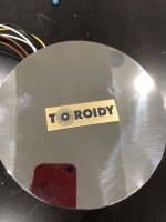
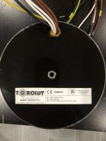
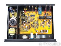
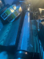
Two items I have noticed though is a mechanical hum from the HUGE torodial transformer, and fair amount of heat.
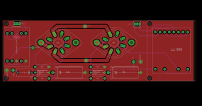
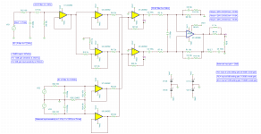
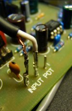
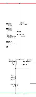
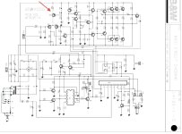
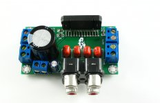
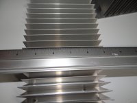
I took a look at the internals, and I do see some heat damage around/near some resistors caused from what I think are bi-polar transistors with heat sinks (which do get really hot) on the board.
The hum from the transformer is somewhat noticeable from up to 4' away with nothing playing.
The amp was put on a variac for awhile prior to my purchase.
I plugged it in and left it for a day, then turned on with nothing attached for a day, then attached to rest of my system.
Again, it works 'fine' from what I can tell.

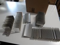
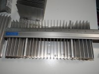
I'd like to see if I can help deal with the heat issue from the transistors, as well as the hum from the transformer.
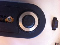
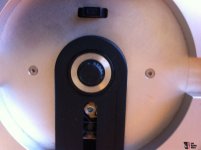
I imagine loosening and re-tightening the hold down screw and bolt for the transformer is where I should start with that, and possibly rotating to see if I can get it to diminish.
How can I help alleviate the heat? Remove the little heat sinks around the transistors clean with alcohol and re-apply thermal paste?
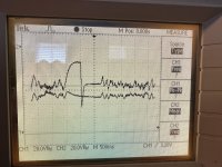
Is there an volt meter test I should do to see if there is an issue with the actual components that is causing the heat?
Images attached.
Last image is from someones sale on USAudio Mart-not my amp.
Thank you for your time and any advice or experience!
image0.jpeg

IMG_1022.JPG

image3.jpeg


3915958-20b4b0ed-vintagesteve-keiser-designed-amherst-a-2000-power-amp.jpg

Class D single power upgrade product. CLASS AB DC12-18V 50W 4R 4channel TDA7850

I always publish something unpleasant.
I'm sorry for this first. But isn't all ascension the result of comparison.
I think I should stand up and tell others.
Class AB dc12-18v amplifier. Very cheap. It's simple. Maybe it will last for a year. It will pay an extra $0.5 for electricity.
I've heard of it. Many people use the tda7850 to upgrade the class D amplifier that comes with their cars.
The result is a big improvement. I think home should also be OK. I found that many people use dc12-18v DC power supply to make household amplifiers.
It is much better than tpa3116. I think it also exceeds tpa3255 or ma12070
The total cost of the amplifier is less than $10.
It includes 4 channel amplifiers.

The TDA7850 is a breakthrough MOSFET
technology class AB audio power amplifier in
Flexiwatt 25 package designed for high power car
radio. The fully complementary P-Channel/NChannel output structure allows a rail to rail
output voltage swing which, combined with high
output current and minimized saturation losses
sets new power references in the car-radio field,
with unparalleled distortion performances.
The TDA7850 integrates a DC offset detector
DC supply voltage 12-18V
Max. output power VS = 14.4 V; RL = 4 R 50W
,VS = 14.4 V; RL = 2R, 85W
THD Distortion Po = 4W 0.006%。 Po = 15W; RL = 2R 0.015%
SVR Supply voltage rejection f = 100 Hz; Vr = 1Vrms 75DB

Attachments

  • IMG_2984_副本.JPG
    IMG_2984_副本.JPG
    156.8 KB · Views: 306

Compare simulated and actual phase - from each drivers measured separately connected with its own xover

I want to check if my 3 way drivers are really in phase as compared to the simulated xover . Let's say that in my vituixcad xover sim, my midrange driver is the one to reverse in order to have a big dip which will confrim that I will get a good phase tracking.
Now if I measure each driver separately with its own xover and export each FRDs into Vituixcad, will the new simulation ( with midrange reversed and no additional components added ) reflects more or less the same dip.

Preamp help

Hi guys, I need a little help from the gurus!
I'm using a MiniDsp for its DiracLive function and running it into an Emotiva amp. However, Dirac Live exacts a 20 db penalty (something about not running into digital clipping) so that the MiniDsp is running nearly flat out but my music doesn't have near the dynamics it did - just sounds flat. Jumping around the MiniDsp restores proper dynamics and volume levels.
I'd like to build a simple opamp preamp to put between the MiniDsp and the amp. I'm thinking a dead simple fixed gain preamp based on a OPA2134 with a gain of 10 or so - what do you guys think and can you sketch one out for me? Thanks in advance for your help.

Did I get scammed? Sony STR-DE445

I got this AVR for 24 euros and tried to fix it as a fun and learning project.

First the audio video receiver would turn on but had no sound at all.

So, I opened the metal case and noticed some liquid damage marks. Those marks were found on the main board and the digital board.

I disassembled everything, checked every single cap on every board of the amp and recapped when needed.

Also fixed A LOT of cold solder joints and also done some modifications, I added heatsinks on linear voltage regulators, both on the main board and the digital board that were obviously overheating.

I also put a blob of thermal pad under the main board under the main IC201 sound processor because it also overheated.

After cleaning the PCB and doing all the above work I connected it and found that it now works except from the digital board.

When in 2 channel mode it works normally, checked all inputs and they all work and also checked all the amplifier outputs and they also work.

To check all the outputs used the 5.1 CH analog input that bypasses the digital board.

So everything works until I try to adjust the bass or tremble or enable a sound-field, then the amp goes silent, because the digital board kicks in.

Also the digital inputs don't work. But the dolby digital /DTS/PCM 48KHZ input data are properly recognized and shown on the display.

So, after doing some tests and examining the digital board schematic I concluded that the AK4527VQ was dead and ordered replacement from aliexpress. The replacement arrived and I soldered it on digital board but nothing changed. Does anyone know how to find out if I got a faulty IC or maybe I misdiagnosed the fault?

The digital board of this amp is really simple due to cost cutting and very easy to understand. Can someone advise how can I rule out the replacement AK4527VQ being faulty?

I also have a digital oscilloscope and could use it if needed.

Passive Radiator Subs

I have a pair of old original VMPS Original Subwoofers - They are about 20 some years old but still work fine. I have been thinking of upgrading but then thought I have great enclosures maybe I could just upgrade the drivers and passive radiators.

I have noticed that there is very little current information on passive radiators.

Has the Passive Radiator gone out of vogue?

Is there a reason for not using them?

VMPS prided themselves on having a "musical sub" but I have heard that vented and passive radiator subs are slower than sealed and not good for music.

Anyone have any thoughts?

Aleph J Intermittent Cut-out

Hi all! I posted about a year ago while I was doing my Aleph J build and received some great help from y'all. For the past year I've been greatly enjoying my amplifier, though I seem to have some sort of gremlin somewhere. This is / was my first build so thanks in advance for your patience.

The problem I am having is intermittent loss of output in both channels. This occurs perhaps once every hour or two for about 10 seconds at a time. The output cuts out in both channels after a few blips, is completely silent for ~10 seconds, then comes back. DC offset and bias have been confirmed to be in the desired range when the amplifier is functioning. The instability makes it a bit hard to measure for, though I could probably leave a multimeter hooked up and try to get some measurements in the blackouts. I'm assuming it's in the power supply. Operating temperatures seem within normal range, and this problem has occurred in cold and warm surrounding temps.

Thanks a lot!

Harbeth P3 ESR (P3ESR) Clone - which Drivers ?

A friend of me want to clone this mini monitor
I guess, this tweeter under
http://www.seas.no/images/stories/prestige/pdfdatasheet/h0532_19tafd_g_datasheet.pdf
and this bass-midrange driver under
http://www.seas.no/images/E0091-08_W12CY006_datasheet.pdf
or
http://www.seas.no/images/stories/prestige/pdfdatasheet/h1152_ca12rcy_datasheet.pdf
is close to the original drivers - probably custom made.
Any experience with clone of that model ?

Attachments

  • Harbeth_1.jpg
    Harbeth_1.jpg
    124.2 KB · Views: 202
  • Harbeth_3-770x1155.jpg
    Harbeth_3-770x1155.jpg
    73 KB · Views: 182
  • Harbeth-P-3-ESR-SE (3).jpg
    Harbeth-P-3-ESR-SE (3).jpg
    50 KB · Views: 189
  • Harbeth-P-3-ESR-SE.jpg
    Harbeth-P-3-ESR-SE.jpg
    63.2 KB · Views: 194
  • Harbeth-P-3-ESR-SE (1).jpg
    Harbeth-P-3-ESR-SE (1).jpg
    51.3 KB · Views: 224
  • Harbeth-P-3-ESR-SE (2).jpg
    Harbeth-P-3-ESR-SE (2).jpg
    31.4 KB · Views: 443

using MLCC's for critical audio applications

By critical I mean in active filters, equalizers etc.. a fairly high voltage X7R, say 50v rated, looks as though it might suffer a fraction of a % capacitance change with 1V bias across it.
So I reckon for the larger value capacitors slinging a few high value X7R's in series should produce a really stable capacitor in a fraction of the space & price of an 'audio grade' capacitor. By soldering flexible leads on the ends or spacing adequately/orthogonally etc on the PCB the microphonics could be mitigated...
For my application the physical size is crucial, as I'm miniaturising some analogue audio processing gadgets, so obviously surface mount MLCC's would be a great advantage.
What experience or measurements have readers here had/made? Also any information on which product lines are most suitable would be really helpful.

Cheers,
Robert.

For Sale Pair of new SB Acoustics SB17CAC35-4 ceramic midwoofer

Due to changing concept of my diy speaker, I want to let go of a pair of SB17CAC35-4 ceramic Midwoofer 4 Ohm
Review with Klippel: https://www.erinsaudiocorner.com/driveunits/sbacoustics_sb17cac35-4/

Condition: new. I bought them on July 2022 from Masori . de shop but don't have the time to even open the parcel yet. It is still in the sealed package from shop.

Price: 170 euro shipping included in EU.

Attachments

  • IMG_20230410_123426817.jpg
    IMG_20230410_123426817.jpg
    239.3 KB · Views: 87
  • sb-acoustics-sb17cac35-4-tiefmitteltoener.jpg
    sb-acoustics-sb17cac35-4-tiefmitteltoener.jpg
    23.3 KB · Views: 88

Compact LINEAR tone arm with a floating head-shell

Hi everyone,

I have always liked the appearance of conventional pivoting tone arms, as they sit neatly in the upper right hand corner of any turn table; and the turn table that offers the least space for mounting a tone arm is the Thorens TD-124. Consequently all the tone arms I have designed, were designed to fit that turn table.

Even though I also like straight line tracking tone arms, I just don't like the way they take up so much space. So, in 2022 I designed a compact linear tracking tone arm with a floating head-shell to be able to be mounted on a Thorens TD-124 turn table. It is almost as compact as a conventional pivoting tone arm mounted within the confines of the tone arm mounting board in its "at rest" position. To play an LP, it is swung a few degrees counter clockwise to place the stylus at the beginning of the LP's groove.

I designed the tone arm to travel on a track whose length is ~ equal to one half of the modulated distance measured along the radius of the LP. At the head-shell end of the tone arm, I provided an extra wide cradle to allow the head-shell to travel, a distance also ~ equal to one half of the modulated distance measured along the radius of the LP.

The tone arm would be driven by a geared-down CONSTANT speed DC motor, or my preference, a stepping motor. There would be two limit switches to start and stop the motor, but NO servo.

The design is not yet finished and has not yet been built as I am currently involved in other tone arm designs. If anyone is interested in working with this design, please feel free to do so as long as it is for personal use only. I have solid modelled the tone arm and I am attaching three PDF files.

The head-shell travels on two stainless steel rods carried by four ball bearings with a fifth ball bearing preventing forward movement. Miniature air bearings could be used to support the head-shell.

If the groove pitch of an LP would be constant, it would be easy to compute the lengths of the two tracks but, because of variable pitch, computing the lengths of the tracks would be a little more difficult. What I also have not yet designed is a method to return the floating head-shell to its start position.

Sincerely,

Ralf

Attachments

Cornell Dubilier CDE WPP -Series Polypropylene Film/Foil ?

where can I buy the WPP -Series in small quantities (20pc/50pc/100pc/200pc - batches) in Europe ?
https://www.cde.com/resources/catalogs/WPP.pdf
Can you recommend any distributor (that stocks these types) ?

(you get no answer if you send an email (as a company) to cdena@cde.com ... 😒 )

------------

the listed distributors here does not have these in stock:
https://www.cde.com/distributor-search/?country=International&state=Germany

Disc Holder (Center Hub) for CDM12 ind/VAM1252/VAM1254 (Bow Wizard + ZZ8)

The disc holder for this models I don't find anywhere - check out images of this URL's:
https://www.diyaudio.com/community/threads/bow-zz8-cdp-no-sound.237570/
https://www.diyaudio.com/community/threads/philips-cdm12-industrial.158584/
https://www.ukaudiomart.com/details/649229295-hiend-cd-player/
so as the attached images.

Under
https://encosystems.net/product-category/hubs/
there are obviously only the standard versions to find - go to
https://www.hifi-advice.com/blog/cl...lips-cdm-mechanisms-page-3-cdm-12-and-cd-pro/

Is the disc holder from the attached images (from BOW technologies) custom made or also a standard version ?
Thanks for an advice.

Attachments

  • Bow-Wizard-00320-cdbaywocover_wm.jpg
    Bow-Wizard-00320-cdbaywocover_wm.jpg
    104.3 KB · Views: 86
  • 0ezFgNfm.jpg
    0ezFgNfm.jpg
    9.6 KB · Views: 84
  • Y4SgVUZm.jpg
    Y4SgVUZm.jpg
    12.7 KB · Views: 81
  • 1071573-bf7dc0d8-hiend-cd-player.jpg
    1071573-bf7dc0d8-hiend-cd-player.jpg
    77 KB · Views: 93
  • 1071572-e5a2bd0c-hiend-cd-player.jpg
    1071572-e5a2bd0c-hiend-cd-player.jpg
    74.5 KB · Views: 87

Test CD+horn outside before installing in cabinet?

Hello, before cutting the hole for the horn in the baffle on the speaker, can I just install the cone driver in there, and try the cone and compression driver + horn combination with the latter outside of the cabinet and get a somewhat truthful representation of what the combo would sound like inside the cabinet? That way I could change my mind before cutting the hole for the horn. The ported cabinet is already designed with a specific driver in mind but the HF driver is not 100% decided. 10" woofer and 1" CD. Thanks.

Power supply voltage to chassis

Amp 20230417_002336.jpg
I have a home theater amp and when I plugged in the RCAs I noticed a tingle hummmm so I measured from the chassis to the ground in the power socket (amp is double insulated therefore it hasn't got a ground on the plug) and I'm getting 100+ volts AC so out of curiosity I measured what it looks like the primary side (to the left of the transformer in the photo) and every one besides the visible blue and white wires is 1ohm or less to chassis, is this normal? I doubt it is BUT the amp is working..... I haven't tested audio yet as I was about to when I got the tingle but it all seems to be working fine when pressing buttons etc....

Also getting 100v from speaker positive to wall socket ground AND the same of the speaker negative.

Any thoughts would be greatly appreciated

I could use a little help. Are these original Toshiba power transistors (on the right)?

On the left of the image are original 22 year-old Toshibas . On the right are the transistors I bought today. The case, the metal parts and the laser engraving on the case all seem to be professionally made, looking real good (not like many fakes). I think they are probably original Toshibas made more recently. But they look different from the 22 year old ones on the left (maybe no surprise). Any of you seen original Toshiba power transistors made more recently? Are those on the right original Toshibas?

IMG_2304.JPG

Rockford R1200.1d Unstable Power Supply

Hello

I'm working on a RF R1200.1d that appears to have an issue with the power supply.

This version of the amp has 6 big rail caps (3 per rail) instead of the version that has many smaller caps. One of the rail caps on the positive side was noticeably budged, I removed it and will replace it later on.

The issue is that the amp will start causing the speaker to pop/pulse. This is happens with or without audio input, sometimes the popping/pulsing will stop but the speaker will move like there is a 5Hz signal despite no audio input. Sometimes it will work fine for a few minutes and it'll sound perfectly normal.

When the amp is playing normally, the rails looks good - about +/- 66V with ~2-3Vpp of ripple. The positive rail has a bit more ripple (8Vpp) because I removed the bad cap. I have to note that the rails also look good when it starts to pop/pulse as long as I disconnect the speaker.

I've attached a scope picture (CH1 - Pos rail, CH2- Neg rail) of what the rails look like when the speaker starts to pop/pulse. It looks like the rails start to oscillate and will occasionally have some overshoot events (only have seen it on the positive rail, from 66V to ~100V). The overshooting events occurs at the same time as the popping noise as well.

During one of the pop/pulsing events one of the power supply FETs (IRF3205) failed, shorting itself. There are 4 of the IRF3205s on each side of the primary transformer. I removed the bad FET to continue testing.

I've checked the gate drive to the power supply FETs and they look good even during the pop/pulsing events, although the amplitude of the gate drive will drop in sync with the popping/pulsing due to the rail voltage dropping. Could it be because one or multiple of the power supply FETs are latching up and causing this behavior?

Attachments

  • Power_rails.JPG
    Power_rails.JPG
    842 KB · Views: 76

Recommended 2D drafting: LibreCAD

Hi Everyone,

Just wanted to say I spent half an hour, unsuccessfully trying to get AutoCAD LT working. I used LibreCAD on Linux and ... what joy!!

It reminds me a great deal of Drafix, before Autocad bought it. A real pleasure to use for simplicity and accuracy. The one kind of weird issue has been that it is unitless. If you only work in Metric or Imperial measurements you are fine, but if you want to say draw in one but dimension in another it can be tricky.

Anyway, it's FREE, as in BEER and I have no financial interest. 🙂 Good luck.

Erik
  • Like
Reactions: geraldfryjr

What’s this subs 8omh RMS?

I got this amp it’s says 1200w Max blah blah…

The actual rms is 2x
BFD3AA30-EED2-4996-9FFB-D64980F01B10.jpeg
200w for 2omhs

I got a sub coming that’s 200rms 400max
It should be fine, the amp got 2 speaker outputs and it’s 2-16omh amp, could I run my sub from one speaker output and my 4x30rms watt 3way coaxial 4omhs speakers from the second channel?

Running the coxial speakers at 8omhs will make them take 60rms, just not sure can’t find the amps 8omh load rms but am guessing from the image above it’s somewhere 70watt at 8omh

Please correct me if am wrong

This is for home project I already am running my coxial speakers with a cheap amp.

What happens to the fundamental?

I built a sealed kundt tube 200 cm long with drivers on each end to ‘see’ AND hear resonance, etc..

. It goes nuts at 172.8hz and forms these shapes.. (the video is super cool looking in slow motion!) the other freqs dont (Barely) form any shape ? What’s up with 86.4, it doesn’t form the ‘stripe shapes’ within the sine wave formations of gathered vibrating styrofoam beads?

I think I can email (?) or FB messenger the short video

Attachments

  • image.jpg
    image.jpg
    476.5 KB · Views: 124
  • ADD2C679-C530-4D98-A3E8-901A38529DD7.png
    ADD2C679-C530-4D98-A3E8-901A38529DD7.png
    97.3 KB · Views: 112
  • E8351834-EE53-446D-B347-951646EF7884.png
    E8351834-EE53-446D-B347-951646EF7884.png
    473.7 KB · Views: 115
  • image.jpg
    image.jpg
    374.3 KB · Views: 126
  • image.jpg
    image.jpg
    317.5 KB · Views: 120

Crazy things your parents said

This might be a good place to list crazy things our parents told us. I’ll kick off with two from my mother (RIP)

1. ‘Do not take your radio into the bathroom! Do you know how many people have been electrocuted doing that?’

The radio in question was one of those tiny el cheapo MW/SW jobs powered off 2 AA cells.

2. On chewing gum (I was about 12 at the time) ‘Spit it out now! Do you know how many kids choke to death on chewing gum every year?’

😂😂

Using a sound card to drive an amp

Not sure where to ask this but PC based looked to be ok. ') I hope.

I have an amp with ~25db gain. What I am not clear enough about is the drive capabilities of sound cards and usb audio interfaces. The sound card is USB Soundblaster Xfi. Outputs on the back marked line in / phono, and line out. The USB audio interface is similar but with a dedicated mic input. I assume there are some standards.

What I don't know is the line out's capabilities. Details on the amp are scant other than ~25db gain and capable of 2x50w but I will probably running at a voltage that doesn't allow anything remotely that powerful. It's spec'd down to 6v where it will only produce a few watts. It will only be used for freq sweeps and spl measurements.

Simple LED display for DAC freq?

Wondering if anyone knew of a simple circuit to indicate the active DAC sync frequency with single LED's? I have seen one circuit that shows whether it is 96kHz or not, I think that was just an LED driven by a dedicated DAC pin IIRC. With the myriad of DAC and support chips out there I was wondering if there was something with even more granularity, but not a full segment display?

DIY fullrange OB vs Maggie LRS and OB subs?

So we‘ve rearranged our listening/living space where the speakers can now have 3-4 feet of room behind them to breathe and I’m now luckily in a position to change to OB speakers. Been doing my homework and from a DIY perspective, a 6-8” fullrange combined with an 18” woofer appeals to me……a quality 18 on an open baffle should play smoothly to 250-300hz to meet a FR driver and having no crossover in the mid/high passband is desired. Crossover between the two will be handled with DSP and 4 discrete amplifier channels….i‘m thinking 2 stereo tube amps

…..But then I come to the ready made solution…..a pair of Maggie LRS plus combined with two stand alone OB 18” subwoofers. Obviously it’s more costly and there’s still a DIY effort involved for the OB subs but the asthetics and mutli way panels of the Maggie’s have an allure. There’s also the review bushings everywhere of how fantastic the LRS plus sound……can a 6-8” fullrange compete on an OB? Love to hear your thoughts.

A question about the Pass Mosfet matching technique

The simple circuit that Nelson Pass published in his 1993 article "Matching Devices", even though it was pretty thorough, left me with some questions.

I wondered how he'd arrived at the 15V input value for his tests, and the 2.2k resistor value. The math for choosing the resistor value was in the article, but it mentioned that the input devices should "share the current to within 2mA", and this was based on an equivalent source resistance of 15ohm. No indication of how he got that value, so I looked further back in his publications. I found that the whole thing was a reprint of a portion of his A75 amplifier two part article from the previous year. In that article, Nelson showed his calculations were based on testing the IRFD110.

So now my first question is, how were the choice of input voltage (resistor value plus V at the supply) arrived at for matching these input pairs?

I've looked at how people are matching parts for Nelson's modern designs. The Aleph J uses the IRFP240, and folks are still using 15V with a 2.2k resistor. Just glancing at the data sheet I see they have identical Vgs. So is that the main factor for picking the test voltage and resistor? If so, how would I arrange the test for different Vgs? If it was 2.0 or 3.0 or 5.0, what resistor would I place in there?

Or, since these are for input pairs, should the value stay at 2.2k with a 15 volt input no matter what the Vgs is?

1u 4-endpoint streamer / DSP / DAC?

Anyone know of any projects to build something like this based on Pi or something else:
[The goal would be to have 1u of 4 x 2ch of flexible audio processing to pair with a 2u 8ch amp (e.g. Buckeye) as part of a housewide multiroom setup that could be controlled from a phone or a media server of some sort (e.g. Roon)]

Internet > ETH > [[Some device presenting 4 streaming endpoints (Airplay 2, Chromecast)]] > DSP processing > DAC > 8 channels analog out > Amp > speakers

?

There's the Arylic M400 4-Zone Preamp that comes pretty close, but it doesn't look like you could load any DSP / room correction software onto the device.

Even cheaper than that (& more capable?) would be to put 4 Arylic Up2Streams into a chassis, but I'm still wondering how to do DSP before the DAC.

I'm guessing there are reasons others aren't solving this problem, so please let me know if this is a silly question.

Thanks!
Jeff

Reduce Cone Excursion

I repaired 2 amps from a jbl 7 series monitors. Trying to use them in my first higher end build of diy active monitors. I was looking to use the Dayton audio esoteric 7in woofer. Put all the data into winisd and playing with the box size and port. Got everything dialed in until I got to cone excursion, it's way off the charts. Can't figure out how to get it down. Only way I can get it below the xmax of this speaker is to set the input wattage to 10w. Changing box size and port values don't seem to do a lot for the cone excursion. I feel like I must be doing something wrong.

Restoration of old speakers by a novice - need help with crossovers

Hello, this is my first thread here. I know this question has been asked before, but as an absolute newbie at this I want to be sure what I'm doing, not to mess something up. Just to mention that I am technically literate, I can work well with a soldering iron, I have measuring equipment, lathes and calculators to make coils, but I don't have the theoretical knowledge.
I'm restoring speakers made in Poland, Tonsil Tango 200. They were in poor condition and missing a lot, but I was able to collect everything I needed, repaired the cabinets, but couldn't find the original midrange speakers.I have currently purchased speakers of the same model, but instead of 15 ohms, they are 8 ohms. I need help on exactly how to change the crossovers in the midband so that I keep the bandpass unchanged, without muting the midband, and without changing the total impedance of the speakers.
I would be very grateful if someone could help me, as a newbie, how to deal with this situation.
I will attach the schematic of the original crossover, as well as the specifications of the original midrange speaker, and the replacement I have. The original speaker is 16/50/4 - 15 ohms and the replacement is 16/50/6 - 8 ohms. Thanks!

Attachments

  • Screenshot_20230411_111404_com.microsoft.office.officehubrow.jpg
    Screenshot_20230411_111404_com.microsoft.office.officehubrow.jpg
    221.9 KB · Views: 154
  • Screenshot_20230411_111552_com.huawei.browser.jpg
    Screenshot_20230411_111552_com.huawei.browser.jpg
    188.5 KB · Views: 155
  • zwrotnica_tango_200_4143.jpg
    zwrotnica_tango_200_4143.jpg
    37.3 KB · Views: 158

Pass Aleph 5

Hey all. I'm building an Aleph 5 kit. Mr. Pass specifies 34VDC for the rails. How high can I push the rail voltage? I have a 30V transformer which will give me around 42VDC after rectification and wanted to know if it is going to work without stressing the MOSFETs? Also would it increase the temperature of the MOSFETs if I use higher voltages? Thanks for any feedback.

Roksan Radius 5.2 to 7 motor upgrade

Hi you all - trying to upgrade my Radius 5.2 motor to the Radius 7 - There's an old post from 2018 where an user did the same however it's been very difficult to get any responses from Roksan, not sure if due to the fact that they were acquired by monitor audio and the Radius line has been discontinued. Anyone with any tips? Appreciate it very much! Thank you.
Projects by fanatics, for fanatics
Get answers and advice for everyone wanting to learn the art of audio.
Join the Community
507,667
Members
7,883,441
Messages

Filter

Forum Statistics

Threads
405,990
Messages
7,883,441
Members
507,667
Latest member
lou.trane