I built my own charging case for the Bose QuietComfort 35 / QC 35 II / QC 45 / QC 45 SE Headphones

The "charging case" is more a custom built power bank that fits tightly into the original case (or an aftermarket case) than an actual "charging case".

1676667953254.png


The build is based around a 3D-printed enclosure, an off-the-shelf power bank PCB with micro USB in and USB out, an 800mAh 16340 (CR123A) li ion cell (I used a protected cell from EEPOWER because you know, reasons) and a cheap CR123A battery holder.

You cannot charge the case while it is closed and you cannot pass-thru the power to the headphones while charging the power bank. If anyone is interested, I can upload the mechanical files (Fusion 360) and the BOM to github but it will take me a couple of days. The design is not 100% finished and I am currently testing. Once I am done, I am going to glue it in place.

I have ordered an angled USB cable because I was unable to make it fit nicely with the original cable as you can see.

It should work for

Bose QuietComfort 35 / QC 35 II / QC 45 / QC 45 SE Headphones​

as they are all the same form-factor.

Cheers, André

Is your servo ruining the sound?

I have a Sumo Polaris which I have used for several years. Sounds great for a few months, then sounds annoying. Bias is fine and THD adjust pot all where they should be.

I wonder if the problem is in the servo which uses a 16uF integrating NP electrolytic capacitor and an (eek) LM741 operational amplifier, a Nat Semi original. Cordell, in both editions of his book has written extensively on servo's, reminding that the servo is in the signal path. Perhaps the electrolytic cap is suffering some inconsistent leakage issue, perhaps the RC-time constant of the servo is much too great.

Goodmans Triaxiom 1220c

Recently purchased 2x 1220c's and didnt realise the attenuators/crossovers had been removed and the pictured ones are not Goodmans........can anyone suggest a way of getting around this??

Attachments

  • $T2eC16d,!)8E9s4l8hebBQujotmDsQ~~60_3.jpg
    $T2eC16d,!)8E9s4l8hebBQujotmDsQ~~60_3.jpg
    79.7 KB · Views: 900
  • $(KGrHqR,!ooFBul4Z8S7BQujpE4PPQ~~60_3.jpg
    $(KGrHqR,!ooFBul4Z8S7BQujpE4PPQ~~60_3.jpg
    86.7 KB · Views: 813
  • $(KGrHqZ,!nwFCqS2NfwFBQujo+TS1w~~60_3.jpg
    $(KGrHqZ,!nwFCqS2NfwFBQujo+TS1w~~60_3.jpg
    94.9 KB · Views: 752
  • $T2eC16J,!wsE9suw)ypCBQujo6Z0B!~~60_3.jpg
    $T2eC16J,!wsE9suw)ypCBQujo6Z0B!~~60_3.jpg
    86.6 KB · Views: 713

Swingin’ on the Gallo’s Pole - a box-free modular line array

This is my DIY project of a modular stereo line array. A bit unconventional because I fastened monitors to the face of a solid pole instead of installing ribbons/woofers inside a hollow column. This simple thinking-outside-the-box [line array pun #1] came from wanting to get close to a live-concert-size (er, should I just say larger-than-life sized…?) feel from the Anthony Gallo Acoustics speakers I like. No matter how loudly I might play a pair, the most recent iteration of “reference” model - Strada 2 - just wasn’t going to feel like a performance hall in my living room. Not surprised. I had no interest in the sum it would cost to import an ol’ used pair of Gallo 5LS’s, and even less interest in the sum such acquired-taste-lookin’ “silver sentinel” speakers would cost my relationship… in a Hong Kong apartment!

I wanted line array performance that could be readily packed away out of sight when not in use. No small feat given the HK apartment constraints (“What’s a garage!?” … “Oh, it’s like closets, and unicorns - pure fiction, I assure you!”). I also wanted the setup to ship with relative ease, if need be. Mine would seem an impossibly tall order [line array pun #2].

Thinking how the 5LS was essentially [on the front] four replicates of the AGA Reference 3.1 top half, with extra CDT’s in between, I began to wonder how such an approach with Stradas - the top half of the well-touted Ref 3.5, might sound. But by then, I needed to use the most recent iteration (Strada 2, with a significantly higher “natural” crossover between woofers and CDT than the original (pre-2012) Strada found on said Ref 3.5, which meant even more technical difference from the 5LS layout. Baby steps needed.

What started in (I think) 2018 as two pairs of Strada 2’s wired parallel on test bench-looking lumber…

06D26780-C632-458E-AF32-CF391E6842E2.jpeg


…has evolved into a setup today that, with a handheld screwdriver, step ladder, and 45 to 50 minutes, I can take down and pack away out of sight.

509DC516-3B2E-4F84-BAE9-4E65F2B7D7C7.jpeg


Hedge all excitement, because the frequency response has not been tested. Even if I used DSP or other treatments, I’m skeptical of a truly flat result given certain features of the room.
Despite possible/likely issues, the human listener response has been positively awestruck in literally every case, so far. Even visitors from whom I expected snide remarks based solely on appearance of the setup, have thrown around the term “perfect” without hesitation. While perfection is surely not reality here, I’m impressed how no one but me has perceived any shortcomings of this setup, yet.

Yes, the subwoofers are needed a bit below 100 Hz, and are not fully resolved as there’s obvious dropout past a certain point in the long room - I suspect a point source bass problem. The line arrays receive full signal, no crossover other than what’s in each powered sub (Gallo Acoustics TR3-D), so I’m telling myself they’re technically full range speakers 😉 and belong in this forum.

No, this project was obviously not cheap, but given it’s flexibility that no other non-PA line array likely offers, and can be built up over time vs. an all at once investment (more on that in subsequent posts if there’s interest), AND is less costly today than the 5LS was back in 2008, it seems a fine outcome based on the performance I hear. Might an entry-level Scaena show better behavior if tested in the same room? I’d expect so. But compare the price points and it’s no competition, for me.

Help with opamps in amp circuit

Hello I've got this amp and there are several opamps in the pre stage. I have attached the schematic of one channel of the amp including opamps.

My first question is can anyone figure out what is the gain of each opamp in this circuit ?

Another thing is do you recommend any modification to the circuit if I were to replace the original opamps with newer variants (such as OP275, or OPA2228, OPA2134 OPA2604 etc.) ? I read that potential problems are either insufficient power or oscillations for newer opamps. I would use sockets so I can keep the best variant at the end.

Thannks for the support

Attachments

Revox A77 power switch

Hi,

I have taken on the challenge of recapping a Revox a77 mklll. After completing each stage and testing, I finally progressed to the basis board on which all controls and switches are mounted.

After completing the recap of this section, the machine does not switch on at all. Even with power bypass pins inserted and remote dummy plug in place.

I have tested the power switch and get 240v on the orange and black wires going into the switch, but no or very low voltage across the blue and white wires that supply the transformer.

Could something have become dislodged in the switch mechanism when the sliding rail was removed? Or has the switch simply failed due to age? Or, have I overlooked something?

Attachments

  • 919571D6-1370-4B41-8D8B-13AF2323D055.jpeg
    919571D6-1370-4B41-8D8B-13AF2323D055.jpeg
    296.5 KB · Views: 254
  • FD3EE53C-FFB8-4D4E-990E-F3D012A272A9.jpeg
    FD3EE53C-FFB8-4D4E-990E-F3D012A272A9.jpeg
    293.1 KB · Views: 237

Need help building mastering speakers

on a 3k budget, i want to build a pair of great speakers for mastering.
currently using dynaudio core59's and eve audio sc408's and as good as they are they're better suited for mixing

now used i can easily find a pair tyler acoustics mm5 or d2s's but from the week ive spent on here just reading you all could help me come up with something even better

i think i want to do something along the lines of the mm5's but with a ribbon tweeter.
i need the guidance, i have madisound and pe open but wish i could plot it out before hand. im sure someone knows a ew softwares to do so

Old parts

Hi mates:
I am former consumer and professional A/V electronic service center.
I am trying to remember wafer switch assembly manufacturer PN# 129.0078, 129.0083, & 129.0091
I think they belong to Sansui, or Marantz or Sherwood. If you remember let me know.
DIY members will receive 10% to 20% off of my old days parts inventory sales you find on eBay. My eBay ID is empire9876.
Most of my parts came from ONKYO, Pioneer, Kenwood, Mitsu, Phase, etc. Being older parts, they are made in Japan, US, UK
Thank You

FREE - Subwoofer Box finished with Black Formica Laminate

FREE to anyone who wants this - must be near Rochester NY and tell me by tomorrow.

BOX was for the Dayton Audio "Titanic" subwoofer kit back in the 90's, but the plate amp quit working and now is gone. I can throw in the working 12 inch woofer at no charge. Reason i don't just pitch it into the dumpster is i thought i did pretty good work on the box itself, so i think somebody might like it. if you are in a fraternity house, or a man cave, or something - not if the wife has to approve it, haha! (it looks pretty good but its huge)

Sealed box, no venting. Made of 3/4" particle board. Outside dimensions 19-7/8" on all sides of the cube. internal bracing. black formica on all sides, still good condition. Cut outs for 12" woofer and 9"x9" plate amplifier. 4 caster wheels on the bottom. Plywood grill frame cut in a circular shape includes grill cloth, snaps on over the woofer hole. if you already have a plate amp, or find one on the bay for fifty bucks, might be worth a try.

Overhung/underhung voice coils

Could someone please point me to a link/thread that details the decisions a driver designer might go through when trying to design a woofer, mid-range driver, or tweeter, specifically regarding whether to use an overhung or underhung voice coil? I have an intuitive understanding that it can involve a tradeoff between moving mass and stationary mass, but there are obviously a lot of subtleties involved. Thanks.

Availability of ASC X386 Capacitors

Hi,

I was going to purchase in the UK some ASC X386s capacitors from RS components, but they have now stopped selling them, I have been talking to the ASC factory and they don't distribute here, and I have been talking to a company in NY and they have finally come back with a price about 3 times the RS sale price I was looking at :-(

Any ideas where you might get some at a sensible / fair price?

Two way PA horn speaker from Pearl

One year ago I discovered a pair of these PA small horn speakers in a recycling warehouse and took them home. It's a two way system with backloaded horn, a cone tweeter and 10" woofer. I hooked them up and they sound pretty good, although the subbass is lacking (obviously with such a small horn). Nevertheless they sound punchy and clear, with good resolution. A good find in my opinion. Now, the question: does anyone has some info on these speakers? I have browsed the internet for details, but there is nothing to be found, not even pictures or data sheets. Also the Pearl website does not mention them. On the back, a sticker only states: 50W @8 ohm, no type- or model number.

Attachments

  • IMG_20230422_181233.jpg
    IMG_20230422_181233.jpg
    117.9 KB · Views: 232
  • IMG_20230422_181427.jpg
    IMG_20230422_181427.jpg
    196.6 KB · Views: 246

12" EV fullrange in open back cabinets

Hi!

A while ago someone gave me a pair of EV SP12B full/widerange drivers.
I kept them in storage for almost a year before I dug them up and put them in a pair of (small) open baffles a few weeks ago. I cross over to a pair of DIY multicell horns at ~900Hz.
OB works fairly well in my assymmetric livingroom but even with a passive EQ network and a low DF amp the bass is a bit light.
Larger baffles is not really an option and there´s no room for properly placed dipole subs so I´m looking for some kind of folded baffle solution.
I believe adding wings at 90 degrees back from the baffles might cause resonance problems, but what if I fill the cavity with some damping material?
Might even add perforated backpieces to keep the stuffing in place (four cats in the house...).
I understand that the dipole pattern would be compromised, though I´m not sure that would be a bad thing. Depending on the hole pattern of the backpieces this may approach aperiodic tuning rather than OB.

I guess the only way to find out if this works for me, in my room, is to try it but I´m curious to hear what other people might have to say about the concept.
I´m a sworn enemy to boomy bass🙂

Electro Voice Sentry 500 monitor driver identification please

Hello all

Hope you’re all enjoying good music.

I recently purchased a pair of vintage Electro Voice Sentry 500 monitors.

They’ve been given to a local speaker repair technician (Brisbane, Australia) who advised the woofers were not original.
He said the woofers fitted are likely from a modern EV public address system.

Would a member kindly advise me of the correct woofer and tweeter part numbers for the 500’s please.

I have searched online and I’m unable to determine the above driver details.

I’m much obliged for your kind assistance.

Mark.

Turntable bearing ball source?

Hello.

I am trying to restore a couple of old turntables, a Sony PS-X50 and a Denon DP-30L II. I am trying to find a good source for bearing balls. The Denon one measures 3.95mm but 5/32 seems to work.

I was able to find these https://www.mcmaster.com/bearings/steel/tight-tolerance-hard-wear-resistant-52100-alloy-steel-balls/ but they don't seem to be a high enough grade.

This is what I was working with for the Denon:
S20220317_0005.jpg


And this is the replacement I received from MacMaster:

S20220317_0007.jpg


If anyone has a good lead for a reputable source, I'd love to know about it. Thanks so much.

DIY HI-FI active 2 way speakers

Hi all!
Im very active on audio karma but im also trying to become active on this form as It seems pretty nice! Ive been browsing a lot on here and now its time for my first post.

Im a broke college student who loves audio engineering and I made my first real nice pair of speakers

Here are the specs
FaitalPRO 8fe200 8" woofer. 95db sensitivity
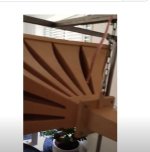
Morel CAT-308 1-1/8" soft dome tweeter in a wood horn. (90 db efficiency but the horn brings it to 96-97db
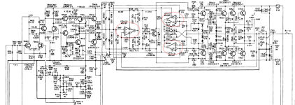
Crossover is 2.3 Khz 12db slope
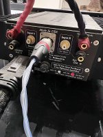
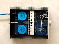
Two Dayton audio KABD-4100 4x100w bluetooth amplifier with DSP. One 4 channel amp is for the speakers and the other will be for the subwoofer I'm making.

Ive done a lot of upgrades that have significantly improved the sound quality such as..

1. removing the faceplate from the tweeter so the dome sits closer to the throat of the horn (more ideal)

2. adding front baffles with a radius along the edges which improved the imaging

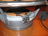
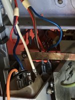
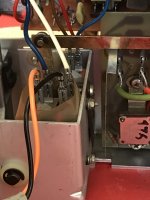
3. upgrading the wiring harness from the stock "aluminum wire" harness to a copper wire harness. this yielded a huge improvement in sound quality. A much fuller, signifigantly less harsh, more detailed sound and there is more "space between the instruments"

4. Using analog crossovers instead of the dsp. Initially there was. TON of hiss and noise coming from both the woofer and the tweeter due to the digital dsp not being able to filter out any hiss/noise after the DSP stage. This also made them sound noticeably less harsh and took the sound to the next level.

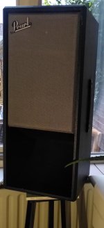
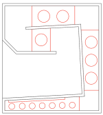
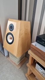
Over all this is a very large bookshelf speaker. The woofer sits in a 1.2 cu ft ported enclosure and I has usable response down to 60-ish hz but I am working on a subwoofer design with a Ciare HS251 10" DVC subwoofer and should have that done in two months or so. so far I've spent $2000 on these speakers (including $700 on super nice 13 layer baltic birch ply for the subwoofer and main speakers)

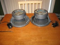
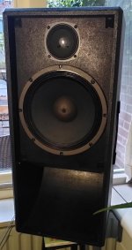
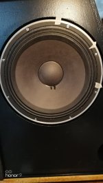
here is a picture of the speakers

IMG_0328.JPG


IMG_0327.JPG


One of the woofers was punctured with a falling clamp so I used silicone adhesive to seal it back up and it does the job but ill be buying another woofer soon .

each speaker weighs approximately 25-30 lbs. very heavy and there is a lot of bracing and sound deadening in each one. The front baffle is removable and the final design will have nice threaded Allen bolts that sit flush with the front baffle for easy removal and better looks.

But how do they sound???

When I made the first prototypes (before all the improvements listed above) they sounded lively, dynamic, but very harsh and saturated, and they seemed to lack detail and fullness and there was a ton of noise and hiss. after doing all of these improvements, they have fantastic imaging, SUPER clear sound, more "space between the instruments", a much fuller sound, and less hiss. if I had to describe the sound, I would say it is very "luscious" and you don't "hear" the boxes/enclosures nearly as much as when I first made the prototypes. they do lack some Low end authority below 50hz, but soon I will add a meaty subwoofer that should be able to hit 35hz at 113db at peak output. The analog crossover and copper wiring harness both made the most significant improvements to the sound and really took it to the next level.

Eventually I will be 3d printing the horns as the wooden ones don't fit perfectly and are slightly sloppy as they needed a two sided cnc machining procedure which is very hard to do but for now they do the job.
I will also be making a nice wood enclosure for both amplifiers and power supplies that matches the speakers but this is after I complete the subwoofer.

I am already super happy with the sound and they definitely "hi-fi". very very good sound! I cannot wait until the subwoofer is done!

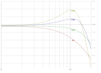
MY ONLY GRIPE is there is some mild distortion in the midrange from the tweeter. im not sure if this is my room (listening in a 20x20 room so im sure there are room nodes) but ill take some measurements of the speakers outside and post them later.

I may try and make better horns but I need help selecting and designing horns so any advice is appreciated!

Parts to build Glass Audio (90) OTL amp

Selling the parts that I purchased 30 years ago to build the Glass Audio OTL amp (back in 1990).
refer to : https://www.bonavolta.ch/hobby/en/audio/6as7_2.htm
I never finished it....
Looking for $250 for the set, buyer pays shipping from California 95032 or local pick up.
  • Magnetek / Triad R-8A xfer QTY1
  • Stancor Xfer 6.3V / @ 1A QTY 1
  • Avel Lindberg toroidal Xfer: Model at/D4046 a QTY 2
  • Avel Lindberg toroidal xfer: Model unknown (if someone has the parts list from the article?)
  • Magnetek/Triad N-51X isolation xformer
  • Fagor FB2506 rectifier x2
  • Vacuum tubes:
  • Sylvania 6AS7GA x12
  • Sylvania 6SN7GTB x4
  • 12 AX7A ( Amperex made in NL)
  • 6EA7 qty 1 ( RCA made in USA)
  • 6DJ8/ECC88 qty 2 (Amperex made in NL)
  • RCA 5763 (RCA made in USA)
  • 12AT7 (Sylvania made in USA)
  • 7025/ 12AX7WA (Sovtek)
    tubes.jpg
    power supply.jpg

The REAL John Linsley Hood Headphone Amplifier

There is a long thread for the so-called JLH Headphone Amp.
Its popularity has of course due to do with the name of Linsley Hood.
But it is also due to the availability of low-cost kits offered on ebay, etc.

In actual fact, this is not really a headphone amp designed by John.
Rather it is a scaled down version of the legendary JLH 10W Class A power amp.

John has published a few circuits specifically meant for headphone use.
A Paul Kemble web page - John Linsley Hood preamp designs.

In particular, the JLH 1985 designed specifically for headphone use is very simple to build.
http://www.angelfire.com/sd/paulkemble/jlhhdphaud.gif
Even in its original form, it consists merely of 3 pairs of bipolar transsitors and a handful of resistors and caps.
And this can be further simplified if one would do away with the auto-biasing circuit.
The topolgy is very similar to the F5 headamp, namely a CFA with negative loop feedback.

We built a modified version, just out of curiosity.
And here is a teaser first.

🙂


Patrick

.

Attachments

  • 180330 JLH1985 Cased.JPG
    180330 JLH1985 Cased.JPG
    318.4 KB · Views: 5,199

Professional advice

While watching this I could not help but think I was watching an audio amplifier shootout. If you fancy yourself an audio reviewer you could take a few tips from this guy, but hey-I exist under the buckle of the bible belt. I apologize to all non-southern U.S. citizens and international members. I don't think that there is a translation program on the face of the Earth that will help you with this one, but I thought you might glean some useful information herein.

Login to view embedded media

Faital Pro LTH102 horn observations and concerns

I was just checking over a new pair of Faital Pro LTH102 horns I received to go with some B&C DE-250 drivers for a 3 way project using B&C 8PE21 in a WG for MF and B&C 15NDL88 for LF.

I had some questions for those with previous experience using Faital WGs -

Looking mainly at the finish work in the casting, I'm somewhat disappointed for the amount of money spent. I specifically don't like the pronounced lip in the throat entry right after the flange. but I'm not sure how much of an impact this will have, mainly on HF performance. There's about a 1-2 mm step roughly 1/2 - 3/4 way around the throat in both WGs (see pic). Seems kind of sloppy for a high priced WG IMHO.

In previous situations like this with other WGs, I did see some measurable differences when removing minor casting abnormalities in the throat. I'd rather not mess with it here if there are no detrimental effects to overall performance. Any thoughts?

Attachments

  • 20220330_081728.jpg
    20220330_081728.jpg
    314.6 KB · Views: 573

Instrument amplification load lines and distortion behaviours

Hi,

I would like to ask to people that designs his own instrument tube amps, what are their preferences.
The most common scenario is to bias at 50-70% of max plate dissipation and then have a steep load line that heavily crosses the maximum plate dissipation.
So the loadline crosses the knee of the pentode on the far right, and being limited to AB1 the anode goes down to 100-70V at max swing.
Then gnfb is used to get some more control on bass, plus add presence and depth.

The only exceptions are most EL84 based amps, that use an Hi-Fi like load line of 8k with bias around 100%, and some old Marshall that run KT66 on 6.6k or even 8k Raa.

Is anyone using loadlines that never crosses the max plate dissipation curve, with or without feedback, and what are the goals you want to achieve?

Thanks
Roberto

BD15 and AE TD15M Midbass Drivers

I am curious if anyone has had an opportunity to compare the AE TD15M with the now discontinued BD-Designs BD15. These are two top performing midrange drivers with no equal in my opinion that I am aware of. For any of you who have performed this comparison, or with any other similar quality drivers, what have been your findings? I am more interested in mid and upper midrange performance of said drivers, rather than bass performance. Which is more open and effortless sounding and with more engaging fast transient response? These drivers are adaptations or evolutions of the Altec 416, and then the JBL E120, which were industry standard for a reason. If high power handling or space savings aren't necessary criteria, the mids produced by an ultra high quality low mass 15" midwoofer 1000hz or below, are far superior to those produced by 12"/10"/8"/6.5" etc and or a high power handling 15".

In addition if one wanted to reintroduce a driver like BD15 -- an ultra low mass and highly advanced high power motor 15" midbass driver, how and with whom would one commission to produce such a device. Thank you.
  • Like
Reactions: camplo

sealed 2 ways with an old pair old Seas 25F-EW

A few years I build a pair of sealed 2 ways with an old pair old Seas 25f-ew 10" woofers and a Dynavox 3" Full range (in its own dagger style enclosure), using a simple 1st order crossover around the 4-500khz mark. About 30ltrs. Heavily stuffed and braced. Very happy with it.

Got another pair of the Seas woofers for super cheap. My Amp is 2.1 and I would like to use extra channel to lower the bass output.
Should a. I be using a separate box as a subwoofer? b. Use another enclosure to turn my current speaker into an improvised double chamber enclosure (raising the overall volume)? Do I even need another woofer to lower the bass output? Would just increasing the overall enclosure volume do the same job as adding another pair of drivers? Reckon I could get away with an additional box of about 40ltrs. Would porting as a reflex help at all? I'm ok with eq.
I'm imagining using a large diameter tube to create the double enclosure and the current speakers would sit on the top (also acting as a stand).

I have hornresp to model this, just looking for tips.
  • Like
Reactions: prairieboy

Tamed the AT440ML

I have owned this cartridge for two decades. It has always been a bit bright. Audio-Technica recommends 100-200pF total load for the turntable, cable, and preamp. This is a low value.

I estimate my system had ~300pF. So, I removed the 100pF loading capacitors from my DIY preamp.

The difference is apparent. The AT440ML now sounds smooth. 🙂

The Internet has a lot of posts about brightness in Audio-Technica's current models. If you own one, make sure that the capacitive loading is under 200pF. 47K resistance works well.
Ed

Attachments

  • at440ml.png
    at440ml.png
    16.6 KB · Views: 197
  • Like
Reactions: vsmusic and mlloyd1

Routing

Very quick and basic question about the miniDSP, is the following right:

If I am using a miniDSP SHD with 2 inputs and 4 outputs, I can implement a 4 way crossover with mono outputs by routing both inputs to each output channel and then applying the crossover filters independently for each output channel?

Thanks

Low Cost Optical encoder for Brushed DC Motor

Anyone can recommend a Optical encoder for Brushed DC Motor? I am working on a new Vinyl and Capstan Motor with Superior speed accuracy.
Like shown here
https://www.powerelectronicsnews.co...rushed-dc-motor-programmable-speed-regulator/
https://www.powerelectronicsnews.com/wp-content/uploads/sites/3/2022/08/10.png

One for normal sized 12v Motor and other for smaller 3V Motor.

I cannot find any reasonably priced one anywhere

Simple question to help me understand why?

Hi,

I have a power supply as shown in a valve pre-amp, and I am trying to understand what purpose the centre tap provides, and what would happen if it was no longer in place?

I also have some 800VAC caps and wondered why I could not put these across the whole voltage drop after the first centre tap capacitor pair?

Thanks for the education 🙂


Screenshot 2023-04-05 at 06.27.48.png

port location to reduce standing waves

Is there a formula or calculator to figure out the optimal placement of single or dual ports on a ported box?
Andrew Jones mentions it while unpacking his latest design
ports.jpg


The idea is to place them such so the enclosure's internal standing waves are cancelled out at the farfield. Does it mean two ports are necessary? Can someone help with this or provide tips?

Purifi with passive preamp, do I need impedance?

I am thinking of making a simple integrated amplifier, consisting of a Purifi power amplifier module.
My idea is to make a simple passive pre-amp with an input selector and a volume control, but do I need to think of input and output impedance on the pre-amp part, or is the impedance that the low ohm input selector, the volume control and the purify makes together?

Best location for an internal amp in Tham 12?

I want to put an amp and boost converter inside my Tham 12 - any suggestions on the best (or least bad) place to put it?

Should I worry about air turbulence caused by the physical intrusion of the electronics into the horn path? I'm thinking about putting it on the back panel, to one side of the brace with three holes shown in red on the right of the drawing attached. It's one of the new 3e TPA3255 amp and Wondom Boost converter.

Any better suggestions? What are the chances of this causing audible noise / impacting the sound of the speaker? Thanks!

Attachments

  • Tham 12 side view.png
    Tham 12 side view.png
    23 KB · Views: 104

Advice on output Impedance selector switch

Would really appreciated some help. I have some Welborne 300B DRD monoblocks and want to add a 8/4 ohm impedance switch/selector on the secondaries of the output transformers. (Drill a hole and fit a toggle switch to the back)

In the manual there are instructions for changing the impedance rating by connecting the different coloured secondary wires together differently, to four posts on the internal amp board

2 ohm and 16 ohm settings are also possible but I think that might get too complicated with the wiring and switch. So I just want to do 4 and 8 ohms.
Would something like a 4 pole 2 way on/on switch be suitable? and what kind of current/voltage rating?

It’s not totally straightforward to wire up, as the output and ground that go to the speaker terminals are connected to different secondary wires for 8 and 4 ohms settings.
The instructions are to solder the configs to 4 posts on the board. I’d obviously be transferring this to a switch.

Pic from the manual is here: https://ibb.co/XS5GQR1

Any help/advice on the right kind of switch and how to wire would be really appreciated. I can solder well but am not so experienced. (I do however know how be safe, such as discharging caps and check with a voltmeter before doing any work)

$2000 Max Speaker

I'm really going to do it this time, I promise! I've been running Magnepan MMGs for the past 15 years, but the buzzing is getting worse due to coil delamination. They sound amazing if you're sitting in the right spot, but I'd like something with better off axis and BASS. I don't want to run a sub currently due to preventing waking up a 1.5 yr old, so I'd like something that can run without. I think I'll put shakers in the couch.

My room is 37' L, and 33'W where the speakers are, narrows to 15' rearward of listening position (most of my house is one room), which is about 12' back. As you can see, the left speaker is in a corner, and I can't come too far out from the wall.

IMG_7105.jpg


I don't want to scratch DIY, but I want to build a known, reputable kit. I believe the main difference between a $1000 DIY speaker and a $20000 speaker is cosmetics. I've built several ugly speakers in the past, but will spend more time making a pretty one this time. I would prefer a bookshelf, but floor standing is okay as well. Any thoughts on the below kits, or any other suggestions? I'd like to spend as little as possible, but would rather spend more for a better speaker than cheap out and wonder what could have been. Oh I forgot: 90% HT, 10% music (all kinds)

Bagby Helios
Rasmusson Elsinore mk6
CSS 2TD-X
Murphy BMR
CSS 1TD-X

NAD C 325BEE Blowing 2 Fuses?

Can anyone offer any advice with this one?
I recapped this NAD amp and upon power on two fuse blew on the power board. So after examining I found two embarrassing mistakes. I had shorted the voltage regulator trace and had installed C524 the wrong polarity. So after fixing these mistakes the fuses still blow. Not the first two, they're fine, but there's an electrical hum sound then the second two fuses blow. The rest of the amp has been examined.

It's a handy amp and I'm hoping to restore this power board.

I've attached pics with red markings to show the fuses that blow and the cap I reversed.

Thanks guys!
20230502_234643.jpg

20230502_234626.jpg

20230502_234614.jpg

Musicality Perception Self-test

I just stumbled across this video of an interesting simple self-test for the interpretation/perception of musicality, for lack of a better term. It helps demonstrate the weaknesses of our human analytical auditory perception - masking, auditory memory and such. The video is 10-months old, so it may have been posted somewhere here before. YouTube link below. Enjoy.

Login to view embedded media

Selecting new 2-way front line based on crossover frequency

Hi,
sorry if this had already been discussed but i didn't manage to find exact answer.

I'm considering upgrading the front speakers of my Skoda Octavia.
As a typical VAG it has 2-way system in the front doors. A woofer in the front bottom part and a tweeter in the A-pillar.

Picture from internet:
1680445560326.png


I've looked over the specs and prices of different aftermarket manufacturers and I've found huge difference in the stated XO frequences ranging from 2.5KHz to 4-4.5KHz.
As far as I know as the frequency rises the sound tends to get directional.
For example here is a simulation of a directionality of a tweeter
1680446596446.png


And here is a simulation of a 6.5" woofer
1680446667992.png


So basically when the woofer is in the driver's footwell then the driver will hear almost nothing from it above 2KHz.

Am I going on the right track thinking that I should limit my search to a aftermarket 2-way system with XO less than 2.5KHz?

Need help with a Borbely DC100 build . . . an output stage cap value is unclear.

This project has been sitting around for decades, and I'm finally getting around to finishing the amp (hopefully!)

The original MOSFET amp build articles are in volumes 1 & 2 of the 1984 TAA. The first article dealt with his Servo amp; the second with the model DC100 - which I'm building.

They both use the same MOSFET output stage, originally spec'd for a pair each of 2SJ49 and 2SK134 per channel (8 devices total). I'm repurposing another amp that has room for only 4 MOSFETS, so I'm substituting UST20N20N & UST20P20 instead.

Borbely notes that the P channel devices have a higher gate capacitance (approx. 300 pF) than the N channel, so he shows 330 pF caps added to each gate of the 2SK134s.

There were subsequent circuit modifications / corrections (1/85 has the wrong schematic!) and then the supposedly correct schematic in the 2/85 issue. The "correct" schematic shows only 33 pF caps added to each gate. I think it's a typo, and it should be 330 as before.

His Hafler DH220 shows a 630 pF connected between the gate of the first device (of two) and the source of the 2nd device.

The XL-280 shows a 910 pF cap shared among 3 devices.

I may have answered my own question, i.e. a single 330 pF cap per N channel device is correct? (I can upload schematics if needed).

Any other suggestions from folks who have built one of these?

Thanks in advance!

Unusual find. Acoustical manufacturing company QA12 with preamplifier

PXL_20230401_144343029.jpg

I've conducted internet searches and this is a rare amplifier. 1 in a 1000 compared to 1 in 90000 for a QUAD II. I'd love to make a stereo pair. Any ideas? Don't worry, I am not going to try switching on, any advice on bringing this all original back to life. New capacitors etc. Or don't touch and keep as museum piece.

Sony CDP-337ESD with strangest problem ever times 2, just listen!

This used to be my favourite player till volumio…
However, after 12 years in storage I decided to listen to it one more time as a reality sound check.
I connected my beloved player to the system, i inserted a cd which was red in a split second, pressed 5, and…disaster hit “private investigations” was completely covered by some kind of very powerful annoying digital noise!
I checked every single electrolytic cap and power supply and regulators and everything is within spec or better! And as if this is not enough I found another guy in youtube having exactly the same weird problem! Check this sound out at 337esd video
What is even more weird, is that I tried an external dac and although it locks excellent, the outcome is exactly the same, a lot of noise!
I have no idea what else to try, thus I really could use some help here.
Any input or idea is welcomed as my experience with cd players is limited.

thank you !

Musical Fidelity X-Can V2 Tube Headphone amp power supply

Dear All, I lost the Musical Fidelity X-Can V2 Tube Headphone amp power supply and I need one. I am not looking for audiophile or fancy power supply. Just the replacement of stock one. The manual says it requires .12V AC 500mA . I have a PYRAMID PS3KX 3Amp 13.8V Power Supply which I used with Musical Fidelity V-90 Dac. Can I use the PYRAMID Power Supply with X-Can V2? I also found this power supply in my stereo system(Picture atttached). Would this work for X-Can? My electrical knowledge is very limited and I dont want to kill X-Can V2 with the wrong adapter. Any advise would be appreciated.

Thanks
Kris

Attachments

  • PXL_20230427_214738166.jpg
    PXL_20230427_214738166.jpg
    460.7 KB · Views: 158

Microphones: What is the relationship between the companies DPA and B&K?

I do not have a clear view but here's what I think the situation is:

B&K shut down their microphone division some years ago
DPA is part of, but not all of, the old B&K microphone division
DPA is the recording / musician product line, but they do not make 'measuring microphones' as such
The old B&K measuring microphone line (example: the 4133) is not made by anyone any more and never had any successors

...Do I have that right? Thanks.

  • Locked
do marketers lie to us too much?

Some of the claims seem very dodgy right from the start. Peloton claims 92% continued users success rate. I also remember many of there sales came during the height of the pandemic. When people can be prone to such purchases out of boredom, or the will was sincerely there. Like usual with gym equipment. 92 percent continued user's I don't believe an inflated claim. It would be a first in that industry.

Its not just there commercial, there are others.

Are consumer's being shoveled way too much poop?

In these capitalistic times I know there wouldn't be any other way.

DF1704 and DF1706 oversamplers (for TI /Burr-Brown DACs only; or generic?)

TI / Burr-Brown released the 96k DF1704 in early 2001, and the 192k DF1706 a few years later, as a companion DF's for their "high-rated" PCM1704 DAC.
https://www.ti.com/lit/ds/symlink/df1704.pdf
https://media.digikey.com/pdf/Data Sheets/Texas Instruments PDFs/DF1706.pdf
What's a bit odd is that the datasheets for both the 1704 and 1706 state: " COMPANION DIGITAL FILTER FOR THE PCM1704 24-BIT AUDIO DAC"
Is there anything inherent to these DFs that makes them compatible only -- or simply ideal for use -- with PCM1704s?
Or are they generic enough to be used with other DACs?

I have a few of each in my parts bin. But I no longer have the PCM1704s. It would be interesting to use the DF1704 for another DAC in my bin, say a multi-bit dac that has no OS built in.

EDIT: Just checked my parts bin. I do have some TI and other manuf DACs that will allow their internal DFs to be bypassed. E.g., PCM1794. This might be an interesting experiment for the DF1704/6.

Help with my first chip amp design using chatGPT

1682496636891.png


Parts list:
Capacitor (C) - 10 µF (microfarads), 50V - serves as both the coupling capacitor and the high-pass filter capacitor
Resistor (Rf) - 2.4 kΩ (kiloohms), 1/4W - fixed resistor for the high-pass filter
Potentiometer (P) - 10 kΩ (kiloohms), linear taper, rated for at least 24V - acts as a variable resistor for the gain control
Non-inverting input resistor (R1) - 1 kΩ (kiloohms), 1/4W
Feedback resistor (R2) - 9 kΩ (kiloohms), 1/4W
Op-amp (U1) - OPAx134 series (e.g., OPA134PA), rated for ±2.5V to ±18V dual supply or 5V to 36V single supply - a rail-to-rail operational amplifier
TPA3118 mono digital amplifier board - rated for a supply voltage range of 8V to 26V, and up to 3A of output current.

Wiring instructions:
1. Connect the bass guitar input signal to one end of the resistor Rf (2.4 kΩ). Connect the other end of Rf to one end of capacitor C (10 µF, 50V). The resistor Rf and capacitor C form the high-pass filter.
2. Connect the other end of capacitor C to the non-inverting input (+) of the op-amp (OPAx134).
3. Connect one end of resistor R1 (1 kΩ) to the junction of capacitor C and the non-inverting input (+) of the op-amp.
4. Connect the inverting input (-) of the op-amp to the junction of resistors R1 and R2 (9 kΩ). Connect the other end of R2 to the ground (GND).
5.Connect the wiper (middle pin) of the potentiometer P (10 kΩ) to the junction of the capacitor C and the non-inverting input (+) of the op-amp. Connect one end of P to the output of the op-amp and the other end to the ground (GND). The potentiometer P acts as a variable resistor for gain control.
6. Connect the other end of resistor R1 to the output of the op-amp.
7. Connect the output of the op-amp to the audio input of the TPA3110 amplifier board.
8. Connect the speaker to the output of the TPA3110 amplifier board, observing the correct polarity (positive and negative terminals) according to the board's specification.
9. Connect all GND points together: the GND of the op-amp, the GND of the TPA3110 amplifier board, and the GND of the external power plug.

I used chat GPT to design an ultra-simple bass amplifier around the TPA3110 and I was following along until step 5, but step 6 says I should connect R1 to the output of the op amp but there is already something connected there. Where did I mess up? Also, how do I "connect all ground points together" when it gets to step 9? Should I physically link the grounds, or does it mean they should all go to the chasis? Thanks for your help!

UT Source sells FAKE Pairs period

I just purchased 2sa970-BL and 2sc2240-BL toshiba low noise transistors neither one looked even clost to toshiba and both had steel leads i have bought transistors for decades and never such a blatent lie the pictures were of real toshiba parts what i got was junk barely legible and both parts measured way off the best one for 2240-bl was 236 HFE and the 970-bl was 209 some were below 200 WOW is all i can say do not buy from them unless you want to destroy what you have buy from AMPSLAB i have bought from him several times although not cheap i have always received good REAL parts from him and he can be trusted another great solution is to buy SMD 2sa1163 is exact of 2sa970 and 2sc2713 is exact same as 2sc2240 they have gr and bl for both and i can tell you what i just bough the 2sa1163 avg was 500 to 510 HFE in BL and the 2sc2713 avg was 480 HFE in BL geat match right out of the package i bought the adapters on Amazon for 50 of them its 8 dollars and i also bought a 100' coil of bare tinned copper wire 26awg solid for 9 dollars i made about 2 dozen pairs in couple hours and results were typical Toshiba very predictable performance and the hfe numbers from them are consistent price was 13 dollars per 100 transistors from mouser for BL and 9 dollars for GR SAVE YOUSELF MONEY AND FRUSTRATION DONT BUY FROM UTSOURCE THEY BURNED ME TWICE IM HOPING I SAVE JUST 1 PERSON THE TROUBLE BY SEEING THIS POST
  • Like
Reactions: Thmartin

Wiggles / ripple on impedance response

I have this speaker I designed and built almost 10 years ago, AE TD15M in 5cu.ft reflex with BMS 4550 on QSC waveguide, active with MiniDSP 2x4 and 4 channels of ICEpower 50ASX2. I've been doing some modifications and improvements, such as bracing and absorption and was taking measurements to re-evaluate the crossover.

When measuring the impedance for the tweeter, I get wiggles on the response curve. I don't recall these from back then, nor from other drivers, but it's been a long time and I used different gear and software back then. Here are a few traces I took as a bit of a sanity check. I'm using REW with a Behringer UCA222 interface and impedance jig with 96ohm resistor, full-calibration.

In case the naming conventions in my legend are a bit arcane:

Violet: 8R2 resistor
Yellow: naked BMS 4540ND, on the edge of a table
Blue: BMS 4540ND on JBL 6" PT waveguide, on the edge of a table
Green: BMS 4550 (unit A) on QSC waveguide, mounted on the enclosure
Red: BMS 4550 (unit B) on QSC waveguide, mounted on the enclosure

impedance_wiggle.png

I wasn't up to detaching a 4550 from the speaker when measuring the above, but a recent 'naked' measurement showed a fairly 'clean' trace, comparable to the naked 4540ND.

It seems that the waveguide-mounted drivers have that wiggle. I was first doubting the seal of the BMS 4550 on the QSC, as I had noticed a certain bow of the mounting flange, but sanded the brackets slightly to bring it back flat and the driver exit seems quite well-fitted to the throat, with slight compression of the gasket material. The BMS 4540ND also fits the 6" JBL waveguide like a shoe, it's like they were made for each other.

My concern was initially with similar ripple on the IR of the tweeter, but I can't do anything louder than impedance measurements at this time in the evening, so hence the impedance comparison above. Here are the IR traces still, tweeter's to begin.

tweeter_IR.png

The woofer's IR does not have these OTOH.

woofer_IR.png

So what could be going on here?
  • Like
Reactions: DualTriode

Vintage JVC

While visiting relatives in Slovakia, i tested my old hifi. If i remember correctly, this i got in early 80's. So this JVC stuff is 40 years old. Still works fine. Tuner is little drifting, signal selector on integrated amp needs deoxit, but all works. The original cassette deck is gone, was warned out, the replacement, not part of this, is great.
Right now there are two sets of small bookshelfs (tesla), as my floorstanders were given to my brother. Together with my real hifi, top of the line Technics.

One thing i noticed, this integrated JVC amp has variable loudness pot, which is usefull. And it does not have preamp section, the bass/treble is part of feedback of power amp. Interesting. I have seen this in Luxman.

If i had soldering iron, i would replace input cap, and feedback cap with mp. But i got nothing here. So it has to stay as is. No recap, no repair was done on this JVC stuff in 40 years.
In US i used to collect SuperA JVC stuff, still have some receivers, cassette deck and cd player. I was always impressed by quality and durability, yet affordable JVC stuff. May not be as fancy as Marantz or Luxman, but for me JVC and Technics was just right.

Posting just for fun.

Attachments

  • 20230426_083304.jpg
    20230426_083304.jpg
    332.2 KB · Views: 230
  • A10X_SM_JVC_0011 (1).jpg
    A10X_SM_JVC_0011 (1).jpg
    52.4 KB · Views: 220

Bad re-coning or how it was stored?...possible solutions?

A few years back i did a trade + cash with a 80 yeras old gentleman that had given up his 30+ year diy JBL project.
He had brand new un used JBL 2235h in orginal boxes from 1994 with same serialnumber on driver and boxes.
He also had JBL 2405h in orginal boxes/same serienumber and also JBL E-145 orginal boxes/same serienumber. ( and some more)

The E-145 and the 2405h was used a little 30 years ago in a project he sadly never finished, and he doesn't remember exactly if they were these E-145s that he had re-coned about 20-25 years ago and then never used again. ( it could have been another pair JBL 2226, he has had many jbl drivers in his life)

No to my problem.
I´ve come to testing/mesauring my new diy jbl speaker, and there is a a slight scraping sound from the E-145.
It looks brand new and are visualy perfect, so it make my real sad someting is wrong with the driver.

Low on cash and not many JBL experts in small Sweden, so i begain to investigate the driver.
With the driver mounted:

If i push the cone with 2 hands ( one on each side) the driver makes a scratch sound with right hand 2 a clock and left hand 8 a clock.
It begains a little at 12:30 a clock, is the worst at 2 a clock and ends at 4 a clock. ( i put tape at the points)

If i only puch the cone with left hand on the left side of the cone at 8 a clock its dead quiet.
Ive read some things about mounting the "problemarea" ( in my case 2 a clock) at 12 a clock and let gravity work.

And maby heat the spider up and let it cool down hanging.
What is my options here?, it so sadly because its like new otherwise.
Are they any chances to solve the glue at dustcup, cone and adjust coil(spider/cone a little ?

I record a video of the sound pushing the cone differant ways on my phone to show you.

Login to view embedded media
Playing bass music:

Login to view embedded media
Best regards John

Attachments

  • IMG_20230501_161037.jpg
    IMG_20230501_161037.jpg
    288.7 KB · Views: 82

Toroidals For Sale

Good Morning.

I have a couple of toroidal transformers for sale in Cape Town South Africa.

1. 60-30-0-30-60 about 250VA comes out of a powered speaker, the amp was replaced with a class D amp and switch mode PSU.
2. 15-0-15 160VA never used plan was to build a power supply.
3. 2x 30-0-30 200VA used to powered a mono 125w RMS amp. I don't have mounting kits for these.
4. 25-0-25 150VA. used for about 1 hour built a 3 way LM3886 amp.

I am looking for approximately R 4000 for all of them but is open to offers.

The person who buys them will also get thrown in
2 x Autona 125w RMS amps with massive heat sinks that is in working condition
1 x gray cabinet with the build 3 way LM3886 amp that is working
1x Gray cabinet that I planned to build the power supply in

Call me on zero eight two eight seven eight three eight three nine.

I am moving and don't have space for all the stuff anymore.

Rowe R-4359A Amplifier

Hi all.
I just picked one of these up for cheap. Anybody familiar with this amp? I looked over a few posts but no real info I could use. I haven't tried to power it up yet. I found a schematic but it doesn't show any of the socket-ed inserts ( i.e... Volume, Mute, Phono Speakers, and external speakers).
I'm assuming I wouldn't be so lucky as to not need to use any of these to complete the circuit. Ultimately, I'd like to use it "as is" as a stereo power amp. I'm not trying to convert it into a guitar amp or anything. Here's some pics. Let me know what you think!

Thanks in advance! :xfingers:

Attachments

  • R-4359low.jpg
    R-4359low.jpg
    525.7 KB · Views: 1,601
  • IMG_0183_zpsl9jqexba.jpg
    IMG_0183_zpsl9jqexba.jpg
    240.8 KB · Views: 1,522

For Sale 1952 Rek-O-Kut B-16H in Rarer C7B cabinet, restored, will deliver within 1000 miles from Minnesota

Price reduction to $3000

I have posted a thread of this restoration project here and she's finished and for sale $3100 plus $400 for delivery.


PLEASE READ THE DESCRIPTION, I WILL NOT SHIP, but I will drop off at the shipper of your choice or I WILL deliver up to 1000 MILES MAXIMUM FROM MINNEAPOLIS (For a Fee) AND MAKE THE TRANSFER OR YOU CAN COME AND GET IT. If you have a shipper who will crate it, send them over. It is also available without the cabinet which may make it easier and cheaper.


Countless hours have been put into the process of rebuilding/restoring and it shows. Everything has been done

REK O KUT B-16H with a Pickering 190D tonearm and a Pickering NOS V-15 Cart. Also has the original C-7B cabinet which most people threw out 30 years ago and this is the only one I have seen except in the 1955 Allied catalog. When I refinished the cabinet, this gorgeous Red Gum veneer was underneath the gray industrial paint and I didn't want to hide it. This unit was in need of restoration. I have a ton more pics and if you are interested, I can tell you what has been done if you message me.

I It has had a new Cardas tonearm wiring kit installed and tested to check for hum. This thing sounds very nice and should last another 70 years. I put in a new motor cap since the original was leaking, rebuilt Idler Wheels by Voice Of Music, 3 speeds (45/33/78) and will play 12" 33 1/3, or 16" 78's and is easy to return it to mono if you want but it sounds great. The Pickering 190D arm may look clunky but they have a big following. It's easy to set up too. It's got a new ATE stylus on it. Speed is spot on. The motor was completely disassembled and cleaned, inspected, lubed and remounted with the OEM motor mounts. I broke it in with about 10 straight hours hooked up to my Phase Linear and the new owner is going to have a showcase piece. Thanks for checking it out. You don't see many of these and this is the only one I have seen with this cabinet which has 2 drawers and would be great to put a nice receiver in the top drawer and some of your favorite albums in and I will be including a very quiet fan system to evac any heat as the back has screen to help it breath.

IMG_6769.JPG
IMG_6768.JPG
IMG_6771.JPG
IMG_6770.JPG
IMG_6777.JPG
  • Like
Reactions: Hifihunter
Projects by fanatics, for fanatics
Get answers and advice for everyone wanting to learn the art of audio.
Join the Community
507,680
Members
7,883,973
Messages

Filter

Forum Statistics

Threads
406,019
Messages
7,883,973
Members
507,680
Latest member
McCoy22