PDFs on transmission lines: Augspurger, MJK

Hello guys!

I have been reading some TL-articles from MJK and also in Vance Dickason's Loudspeaker cookbook (7th ed.).
Many interesting things in there that I didn't know, I was quite delighted to learn so much stuff. On my quest to keep learning I want to ask you guys:
Does anyone of you maybe have some articles written by MJK or, preferably, Augspurger on the TLs?

Especially Dickason's Loudspeaker-cookbook made me very interested in Augspurgers side on this. To be more precise: The articles he wrote for the "Speaker Builder" Magazine in 2000 where he contributed one article per magazine during the year, from an introduction to a more detailed text, I think.

I have already scoured the interweb, but came up with nothing usable. Maybe someone can help me out?

question on using Lundahl Filament Choke LL2733

Hi everyone,

I have a question regarding a different use of Lundahl Filament Choke LL2733. It consists of 2 windings, so instead of using two chokes, I'd like to know if it's possible to use Lundahl Filament Choke LL2733 as below:

Filament filter.jpg


If it's ok then how much is the inductance of each winding and is total inductance of the windings remain the same?
Thanks,

PSU Sanity Check

Team DIY,
I’ve built First Watt style PSU’s from the DiyAudio Store and traditional 5AR4 based tube amp PSU’s, but this is my first power supply like this, so I’m looking for a sanity check. My inspiration for this PSU was a video from Doug De Young. It was very helpful for me.

The amp this will be included in will consist of a pair of E86C input tubes followed by 2 pairs of 6L6 GC output tubes. Each dual triode input tube will be paralleled (using the whole tube for one channel) and each pair of 6L6’s will be paralleled, such that a pair makes one single-ended channel, not push pull. Output tubes will drive a pair of Hashimoto H-20-3.5U output transformers.

My hope is that I can provide a schematic and explain my intentions in the design and then ask for any input you may have. Thanks in advance, I feel like I’m asking for a lot.

This is a class A design.

It will be running on US 120V, 60Hz power.

The load current will be 360mA for both channels combined ((4 E86C plates @ 13mA)+(4 6L6 plates @ 72mA)+(4 6L6 screens @ 5mA)) with B+ at 320V.

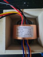
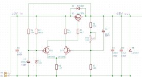
I haven’t picked a transformer yet, but in my simulation, I’m using a 1:2.33 ratio to step up from 120V to about 280V. I’m not including the heaters below. They’ll be on dedicated secondaries as normal, so not as much to think about there.

In the schematic below, NTC1 is a 0.18 Ohm resistor. That’s not for real. I’m having trouble modeling a CL-60 (I don’t know the Steinhart-Hart parameters - a, b, and c), but it has 0.18 Ohms of resistance at full current. I put the resistor in here to simplify simulation.

C1 is a typical first filter cap, if a little large. The bridge rectifier allows up to 240A of surge current, so with a CL-60, I’m well in the comfort zone. R1 and C2 provide filtering for the gate of Q1, but also create a soft-start effect. It takes around 20 seconds for C2 to charge and let the gate come up to full voltage. Because Q1 is in a source-follower configuration, bringing the gate up slowly also brings output voltage up slowly. This might make the CL-60 redundant, but for the cost, I’d rather include it. R3 is a typical gate stopper resistor. D1 is a 9V Zener. The idea is that if the gate goes 9V positive relative to the source, the Zener will allow excess voltage to bypass Q1 and not exceed the Vgs rating (+-20V). R4 drops about 1V, which falls just under Vgs(th) of Q1 (2-4V). That should turn Q1 off in the event of a short (runaway current drops voltage at the Q1 gate via D1, but Q1 source stays 1V higher, limiting current somewhat while it turns off).

Because my intent is to build an over-the-top filtered supply, it’s split into right and left rails at this point, with overkill filtering on both. CLCLC filters get predicted ripple down in the picovolt range (Not sure I buy it, but that’s what the simulation says. It should be good, at any rate.), but ultimately, space constraints may remove 2 chokes and caps.

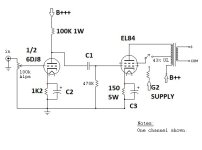
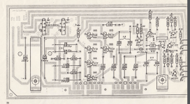
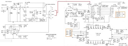
Here’s the circuit in simulation:


x50Fjy8CfV5BheZ1lt9R6v6NCCeLU5afkiy2By9lQz-rhl-jntSERXIqI4uy60nitWafRCvZrmRROgqLKI1upQUzo8-qyAChqxmHmnhBZmN0YV4zGZHEmpZZh3jfg9ZgkbC_GkBh7Ie-6sfrzVRUQC4


Very colorfully, at the bottom, you can see about 319V, 180mA at the load. P-P is the ripple that’s left. At the top right, “Wire” refers to the small segment that’s selected between the supply on the left and the filters on the right. 319V at just under 360mA is very close to the target.

One problem I’ve noted is that this software (oddly) doesn’t account for any DC resistance (and therefore voltage drop) across the chokes. I’ll have to account for that as I select the chokes and can calculate the voltage drop.

I’m happy to provide datasheets for parts that I have selected thus far. I haven’t ordered any parts yet, so if I’m off somewhere, I can correct.

I appreciate any feedback you’re able to provide!

Ryan

R-Core transformer question

I'm putting a small first system together for my youngest son. I've already selected a tube amp and speakers from what I have on hand. I wanted to put together a simple preamp to go with them.
I bought a Zerozone M7 line stage board kit and the recommended R-Core transformer.
I haven't used R-Core's before. The board has connections for the two orange 14v heater winding wires, and the two blue B+ wires. There is a wire marked "N:yellow/green". A dumb question, but
Is this a center tap? I can't get any readings using an ohm meter. Not reading to the frame either.
There isn't any connection for a center tap on the board.
Below is a picture of the transformer and the end of the board where the wires connect. I'm used to heavy iron core and toroidal that come with diagrams of the windings.
Thanks.

Attachments

  • 20240129_084023.jpg
    20240129_084023.jpg
    254.7 KB · Views: 143
  • 20240129_084711.jpg
    20240129_084711.jpg
    371.4 KB · Views: 121

Confused by Specs (Small Subwoofers)

I'm considering adding some sub-bass to my friend's restaurant system. In truth it's just a small cafe. Low power reinforcement is all that's required. It's a cafe, not a car-boot, or a night-club. I want to use 2 x 8" (vented) drivers.
Can somebody tell me why these cheap Monacors are not a good choice?

https://cdn.shopify.com/s/files/1/0809/2387/files/sph-210.pdf?5823

Looking for low drop N channel mosFET or BJT

Hello all. I am looking for an N channel mosfet or NPN bjt for a capacitance multiplier with a very low voltage drop. I am working with some Lithium iron batteries and I would like to clean up their noise a bit to make them perform a bit more like Nicad or Alkaline batteries without sacrificing power density. The circuit is drawing 650ma, and I am having a tough time finding decent parts.

So far I have found the Si5442DU which drops about 0.8 volts due to the limits of Vgs, but I would ideally like to be closer to 0.5v or lower. I'm not even sure that is possible at this point though.

Any thoughts would be appreciated.

Possible 3 Way Build - Akai SW-130 Resurrection

Hello All:

I apparently had an account here the last time I was building a crossover from scratch. Maybe almost 20 years ago. ???.

Anyway, I am back and have a new project going in the garage. My son had a pair of Pioneer CS-88 (???) Frankenspeakers that I built for him when he went away to school. These cabinets were plywood construction with nice veneer and those lattice bamboo grills. Oiled and polished, a really nice vintage look. The guts were essentially Cerwin Vega! 10 inch three-ways taken from donors. These speakers got destroyed by water damage when his apartment caught fire. He is getting a larger place now, and wants to put his vintage system back together. So, I have a project in the garage.

I have Akai SW-130s kicking around for no purpose. I only saved them because they are MIJ and the cabinet materials and construction are pretty good. If they come apart reasonably, the sound board can be replaced with non-metric plywood, and the veneer restores well I will use them. Yes, they came apart cleanly and the sound board is easily, but meticulously, replaced. The veneer is looking good.

Disassembly pics...

20230907_134326.jpg


20230907_134357.jpg


20230907_142127.jpg


Looking to do a 3-way with planar tweeters and soft dome mids. My son hates Vandersteen, but loves Infinity with EMIT tweeters. He likes bright and detailed. He likes my daughter's Infinity Crescendo C3007. (???) With the EMIT.

I am thinking...

Hi-Vi RT1C_A tweeter. PE part number 297-400. Use a high crossover.

Hi-Vi DMB_A soft dome mid-tweeter. PE part number 297-716. Use a wide range with this driver, which should sound great.

Dayton Reference 8.00 woofer RS225. 8 Ohm. PE part number 295-356. ???.

Crossover would start out as a generic 3-way import. I have found a 600 Hz / 4000 Hz and a 850 Hz / 5800 or 6000 Hz. I think the latter would better suit the soft dome "mid" response and allow the higher crossover to minimize any lower-end peaks in the tweeter. From there, mods could be made.

I am concerned that the SPL of the woofer is so much lower than the mid or tweeter, being 86.8 versus 92.0 and 94, respectively. Am I headed for disaster this way? High efficiency would be great, but that woofer is not very sensitive. How would this play out in reality?

There may be an option to use (2) 6.00 woofers, 4 Ohm, in series. The 4 Ohm coil has a sensitivity of 91.8 each. In series, would these present an "8 Ohm" load and preserve this higher SPL? If so, does that not solve a very significant problem?

Dayton Reference 6.00 woofer RS150-4. PE part number 295-372.

Either layout will fit the soundboard. As far as the enclosure volume for a sealed system, the calcs for the 8.00 or the (2) 6.00 woofers looked okay to my limited-experience eyes.

Thoughts? Ideas? Opinions? Hesitations? Run away?

Thanks in advance. I will try to post some data sheets next.

jocko

JL 500/1 No Output Gate after 100ms (Rev 3)

I have a JL 500/1 that was gifted to me to fix. When I got it, Q505 was shorted on the output section, and Q600-607 was burnt to a crisp, the same as R600-607. I replaced the power section fets and gate resistors. Its working power section seems to work. I have D600(rectifier) removed. I have the fets in the output section removed. I have the drain/source of Q505 and Q506 jumpered. I suspected U500 was the gate driver; however, there was no change after replacing it. I am not injecting a signal.

Attached are the gate drives. It's a single trigger for applying power/remote simultaneously. CH1 is the input power, and CH2 is the gate drive. If a look at 40uS would be useful, I can grab that.

It looks like the PWM is trying to come up, and then something latches it. I am not sure. I am not an amplifier expert, and I have only seen the inside of JL once before this. I might be overlooking something simple to you guys.

Can y'all look at these gate drives and give me an idea of where to look next? Does anyone have a schematic?

Q506 gate.png
Q504 gate.png
Q505 gate.png
Q504 gate.png

4 or 5 Channel "Stereo"

I was curious as to who here is using 4 or 5 Channel "Stereo"

I use the Halfer circuit as speaker level in my den/office with 4 channels
In my living room, I split it up into 5 channels at line level and DSP units.
(You don't need the DSP, I just used them since I had them here.)

It's interesting to listen to it and I've come to prefer it over 2 ch Stereo.

The rears are the Difference between the Left and Right and tend to not have any vocals in them
The Front Center is the Sum of the Left and Right and will contain a lot of the vocals.

Low Qts drivers in a sealed enclusure question

I just finished building two sealed 15 inchers for my living room, and I love the sound so much I'm thinking about doing sealed again for my basement subs I'm going to build instead of ported. I currently have a huge Full Marty style sub (48x24x24) with an 18 inch driver and it's very good, but I'm not as impressed with it as I am with my two sealed 15 inchers (that have cheaper drivers in them to boot)

You may have seen my thread a few weeks ago about asking help with the port length for my basement subs, to be honest I was left with more questions than when I came in.

So I have an Eminence NSW4018-8 pro-audio driver, and a LaVoce SAF184.3 driver. Both really want to be in vented enclosures.
Eminence: Qts 0.36 EBP 92
LaVoce: Qts 0.32 EBP 88.

If I build a box the same size as I was planning (32 inches x 24 x 24) I get critically damped QTC 0.5 in WinISD. I could make them a bit smaller to get the QTC up slightly if I wanted to.

My question for you guys, can I make this work by brute forcing it with power? I have a Lab Gruppen clone FP14000 plugged into 220v. It has like 3000w or something stupid at 8 ohms and I can run it in bridge mode into less ohms if I need to. Edit- I also have a DDRC24 with Dirac for EQ.

This system is 98% used for music, and death metal is easily 70% of what I listen to. It demands extremely fast extremely tight bass. Once in a while I'll watch a movie while on the treadmill, or I'll listen to some electronic music with super deep bass, but it's not the norm. I'd like for those low notes to hit as hard as they can, considering it will be two 18 inch subs. If you don't feel the low notes with two 18 inch subs something is very wrong!

Attached WinISD, my living room setup (I'll make a post about the project soon enough) and current basement setup with the Full Marty (excuse the bad paint job, new ones will match the speakers)

Speakers in the basement are Crites model B CornScalas (Klipsch Cornwalls with the La Scala squawker, woofer crosses over at 500hz instead of 700hz)
Speakers in living room are Magnepan MMGs.

thanks!

1705024953688.png


Living room subs 15 inch Dayton MX 15-22
1705025015699.jpeg


Basement sub, it's the Eminence NSW4018, TV is 85 inches for scale
1705025094806.png

Sun Audio SV-300B PP - Overshoot on square wave test

Hi all, I'm looking to tweak my Sun Audio monoblock amps a little (just some cap and resistor changes and maybe a separate filament transformer) and I thought I'd start with some baseline tests before I change stuff.
I have an Analog Discovery 2 and using the excellent and free Audio Analyzer Suite I'm running a few tests. Generally the distortion is very low and the THD vs Power report shows I get a clean less than 0.5% distortion up to 8W before they max out.
But the basic Square wave scope test shows some pretty wild overshooting. This test is with a 1000hz 0.2vrms Square wave to the input phono and measuring with the probe at the GND and 8ohm speaker terminals with an 8ohm dummy load across it.

zzzscreengrab1706307968001.jpg

Both the left and right amps are identical in their measurement and this overshoot characteristic.
Do you think this is a cause for concern or just a very simple amplifier circuit responding to an unusual test?
Is there anything simple I can do to improve this?

The amps are 300B push-pull with no negative feedback. Here's the circuit

schema300BPP-2.jpg

Just for reference, here's the sine wave test

zzzscreengrab1706308197001.jpg

the distortion vs frequency

zzzscreengrab1706307147001.jpg

and the distortion vs power (not quite the advertised 20W max, but 8 clean watts is plenty for me.)
zzzscreengrab1706307381001.jpg

Resistance with random crackles in Sansui AU4900, is it possible?

Can a failed carbon resistor cause random noises in an audio amplifier ?

https://www.electricalvolt.com/2023/07/carbon-composition-resistor/

In the article it mentions that carbon resistors can cause "random" type noises, but I don't know if this description can be applied to my problem, which by the way is quite puzzling.
I'm trying to bring an old Sansui AU4900 amplifier back to life. It systematically refuses to work without random noises. You can use it for whole days without problems, after a long break, you turn it on again and BOOM! crackles arise that you think are going to explode the speakers sometimes, other times they are weaker, etc. I have made all the TR changes they recommend on this amp. ALL 2SA726 and 2SC1313 from the pre, and IC2SA798 from the power board. The problem persists over time (luckily it is not the only amplifier I use, but it has sentimental value for me and I would not like to consign it to the trash can.
So I think I should look elsewhere for the culprit, ruling out the TR, could it be a out of value/damaged resistor that causes this?

Obbligato PSU capacitors anyone?

Today I received a a few 47uF Obbligato PSU capacitors that I ordered from diyhifisupply a few days ago.
They are big cans and diyhifisupply sell them for a very favorable price, if they work as intended.

At a first glance they look very much handmade, almost as if they were built during an art and craft class.

As soon as I go back to my workplace I will take them to the electric lad to measure the capacitance and the ESR, and for some thermal and voltage stress test.

There is not much information on the web about these capacitors, aside from having an astounding df=0.00015 according to the resellers.
Has anyone had any real life experience with them?

Attachments

  • PXL_20240119_061348548.jpg
    PXL_20240119_061348548.jpg
    260.7 KB · Views: 177
  • PXL_20240119_061429155.jpg
    PXL_20240119_061429155.jpg
    261.6 KB · Views: 158
  • PXL_20240119_061441828.MP.jpg
    PXL_20240119_061441828.MP.jpg
    216.4 KB · Views: 161

RCF CX15N351, active closed carbinet, Hypex FA503 FIR

Dear forum, I got two 15" inch coaxial drivers (RCF CX15N351) quite cheaply, so I would like to use them to build two active speakers in a closed cabinet. Since these speakers will be my first DIY, I unfortunately have a few questions. Maybe you can give me a few tips/answers regarding literature, videos, tutorials that could be helpful for the first start.

So far the plan is to build a loudspeaker very similar to the Martion Bullfrog loudspeaker, but with a built-in active module:

- Closed cube design

- RCF CX15N351 with modified 3D printed horn

- Hypex FA 503 (New one with FIR Filter)

- Hypex OLED display

The whole thing should be controlled via SPDIF and possibly supplemented with a suitable subwoofer in the future.

The following questions have already arisen:

- Regarding the cabinet: Unfortunately I have problems determining the volume (liters) for the driver. The comparison speaker “Martion Bullfrog” has external dimensions of 45x45x45 cm. Does anyone have experience with a 15" coax in a closed housing? Does it make sense to line the inside with insulating materials? If so, what would you recommend?

- The horn of the RCF CX15N351 has a cutoff frequency of 800hz. According to the information, the Bullfrog's crossover frequency is already at 680hz. The horn was probably enlarged by the aluminum ring. I would like to make a new horn using 3D printing and would have the opportunity to customize it even further. What do I have to pay attention to if I want the cutoff frequency to be lower? Larger horn opening? Are there programs that can simulate horns? And has anyone ever created a horn using 3D printing? Are there preferred materials?

- How do I set the limiter of the Hypex so that the chassis is protected? Simply enter the wattage of the AES / RMS / OHM value?

- Is it possible for me as a “beginner” to calibrate the loudspeaker with free programs (REW / rephase) and create a crossover with Fir filters after watching some tutorials / videos?

I know that it is a very ambitious project for a beginner, but I would also like to learn the basics and measure the speakers myself in the future. Please give me honest answers if the project is too big for me and you think I would despair about it, then I would rather sell the chassis 😀

Thank you very much in advance!

How do I calculate the capacitor values in a SE amp? Coupling + k bypass

Greetings Friends. I've built a nice little amp
IMG_20240126_091644125.jpg


Hammond 270DAZ PT, 6CA4 rectifier, EL84 output tubes, EDCOR GXSE15-5K OPTs. Currently using 6DJ8 as driver tube but I'd like to be able to use any b9 tube as I also have 6N1P, 6N6P, 6N23P etc I would like to try out. The power supply is borrowed from @Suncalc Marblewood amp:
ELF AMP PS 1.png
IMG_20240126_091722761.jpg


There's a switch on top to choose Pentode or U/L, and a pair of DPDT switches on the back to control FB and the v1 bypass.

I wired up the amp with a Suzuki circuit I found over on Single-Ended.com

EL84single-Amp.png


with the 33k resistor before the driver supply cap, the supply voltage is quite low, I measured ~32v on the plate of the driver tube. The amp sounds fine, but I'm wondering if the driver tube should be operating at a higher voltage. Perhaps a larger 1.2k K resistor and a smaller resistor for the supply would get the operating point closer to the middle of the load line.

But How do you calculate that coupling cap? the grid leak for the power tube sets the impedance for the stage? this is where I'm lost. And the bypass caps? Here's a circuit schematic with the unknown values:

ELF CIRCUIT 1.jpg

Attachments

  • ELF CIRCUIT 1.jpg
    ELF CIRCUIT 1.jpg
    27.6 KB · Views: 103
  • Like
Reactions: gerrittube

QA404 ante portas

https://forum.quantasylum.com/t/qa404-and-qa403-update/795
The price keeps climbing $650.
https://forum.quantasylum.com/t/qa404-availability/789

"Update Apr-7-2023: After a long period of the product being out of stock due to silicon shortages, we expect to start taking order"s and shipping QA403s again next week. The shortage issues are still ongoing in various forms, so expect some hiccups in the coming weeks and months."

"..the QA404 hasn’t started selling yet, but it should in the next few months. The newsletter email signup is linked below. When it’s ready, there will be an email sent out."

For Sale Elekit TU-8600S amp for sale

This is an excellent amp but I now have too many and want to continue with different First Watt builds. No operational issues or blemishes (missing 3 screws that hold the tube cage down). The missing screws make it easier to access and there's enough to keep it held down on both sides.

All the tubes listed are included. Here are the details:
  • Elekit TU-8600S purchased from diyaudiostore.com
  • Came with Takman resistors, Lundhaul transformers, and ALPS R27 pot
  • Upgraded coupling caps to V-CAP ODAM (purchased from Victor Kung)
  • Tubes (bold lines are my favorite combo):
    • 2 x 300B Takatsuki (yes, the $1,700 ones) - the original wooden box top split but can be glued -- still protects tubes for shipping
    • 2 x 12AU7 RCA Clear Top
    • 1 x 12AX7 RCA blackplate, medical grade, red tip
    • 2 x Genelex Gold Lion ECC81/B739/12AT7
    • 1 x 12AX7 Northern Electric
    • 1 x JAN-GE 12AX7WA
    • 2 x 12AU7 Mazda/Telefunken NOS (one is weak -- box is labeled)
Asking $2,800; buyer pays shipping if not local pickup. Paypal works well (cash @ local pickup will save you $100).

Local pickup (Overland Park, KS 66213) would be great, but I can arrange buyer-paid shipping. PM for a shipping quote. I'll package the tubes in their original boxes, shipping the Takatsuki's separately. The remaining tubes will pack in bubble wrap inside the amp cage to keep them safe.

Thanks,
Chris

Attachments

  • IMG_1221.JPG
    IMG_1221.JPG
    823.6 KB · Views: 200
  • IMG_8508_edited.jpg
    IMG_8508_edited.jpg
    171.7 KB · Views: 183
  • IMG_8510_edited.jpg
    IMG_8510_edited.jpg
    186.8 KB · Views: 171
  • IMG_8512_edited.jpg
    IMG_8512_edited.jpg
    229.9 KB · Views: 169
  • IMG_8513_edited.jpg
    IMG_8513_edited.jpg
    155 KB · Views: 183
  • Like
Reactions: OtisCampbell

For Sale Middle Atlantic CH1 Chassis

Brand new Middle Atlantic 1U chassis. $50 plus shipping costs to a CONUS only address

Middle Atlantic CH1 - The Middle Atlantic CH Chassis CH1 is a rugged, rack-mountable chassis featuring a screw-less, flush-mounted faceplate. Its body and faceplates are all constructed from 16-gauge steel to allow for easy machining and customization. The front faceplate features a brushed, black, anodized finish, while the rear plate is finished in black, powder coat.

Mid Atlantic CH1.jpg

Attachments

  • Mid Atlantic CH1 pic 2.jpg
    Mid Atlantic CH1 pic 2.jpg
    43.5 KB · Views: 90
  • Mid Atlantic CH1 pic 3.png
    Mid Atlantic CH1 pic 3.png
    13.5 KB · Views: 84

Getting low sound with SL-BD20A (Technics)

Hello everyone.
I want to use my old SL-BD20A turntable again. It's been unused for years.
I now have a Yamaha RX-V863 receiver that works fine (CDs, DVDs, radio, etc.).
I plugged my turntable in the phono jacks + the ground of the receiver.
But, the sound is very very low.
I am wondering if it's a stylus/cartridge problem. Or, if I need a preamp. (Maybe both).
Any help?

Volumio with 10" touch screen

Hello. Here my take on a streamer (have currently 3 in various build stages 😀 )
It uses a Pi4 with Volumio, M.2 board soon to be added, Meanwell enclosed PSU, 10" waveshare touch screen and D10S guts as a DAC. I am not happy with the case, I messed it up 🙂 will be ordering new one and keep it original black anodized. Thinking going headless, to match my pre and power in same case.

Dont mind the Alto active speakers 🙂 they are used in our cottage for partys and celebrations.

Danny

Attachments

  • 2.jpg
    2.jpg
    290.3 KB · Views: 115
  • 3.jpg
    3.jpg
    319.2 KB · Views: 107
  • 20231121_220516.jpg
    20231121_220516.jpg
    719.2 KB · Views: 103
  • 20231207_095232.jpg
    20231207_095232.jpg
    337.1 KB · Views: 102
  • Like
Reactions: VimalD123

I2S isolation for DAC

I am currently working on a USB DAC project as a part of a headphone amplifier. My idea is to use the AK4493 as my DAC and the Amanero Combo384 as my USB to I2S interface for the DAC.

I am afraid to have some kind of ground-loop or noise introduced from my PC which is why i am considering a galvanic isolation somewhere between the PC and my DAC chip.

Amanero recommend the use of an ISO7640 4ch 150MHz isolator. But their solution does not let the masterclock pass through the isolator.

Would it be a solution to change the chip form a 4ch to a 5ch to let the masterclock pass through, or will the isolator introduce more problems than it solves when used for the about 22MHz masterclock?

Or should I drop the isolation and go for an entirely different way to minimize noise and ground-loops originating form the PC side of the USB interface?

Attachments

For Sale Iron Pre Balanced kit + full BOM

I have an already excellent working condition Iron Pre balanced as preamp now and the second kit I purchased as buffer for my dac. Plans have changed so better to make someone else happy with it.

Up for sale is the full balanced essentials kit plus everything needed to complete the boards, except for the Lorlin switch and relays.

See picture below:

IMG_20240126_144626.jpg


Asking USD 250 plus PP fees and shipping.

NAD C 515BEE randomly stops playing

Hello,

My C 515BEE randomly stops playing the CD for a fraction of a second and then resumes playing. It occurs on every CD I play, even brand new ones.

When the sound stops, the time counter switches off (only the time, not the whole display) and reappears when the sound comes back.

Do you know which component(s) should be replaced?

Thanks for your help.

The room correction or speaker correction? What can we do with dsp power now availabl

Hello,

I see high interest about the subject here. I would like to offer my expertise collected in 14 years of serving professionals.
Let’s start with discussion with Dr. Floyd Toole about his paper "The Measurement and Calibration of Sound Reproducing Systems":
https://secure.aes.org/forum/pubs/journal/?ID=524

The full version of discussion is available here:
http://aplaudio.com/downloads/Reading_Dr_Toole.pdf

And what can be corrected – loudspeakers or room:
http://aplaudio.com/downloads/Equalizing_loudspeakers.pdf

BR,

Raimonds

p.s. #1 2016.01.08

Problem to solve:

How to get uncolored performance of a loudspeaker to meet high accuracy requirements of recording industry. It is completely different accuracy level comparing to sound reproduction for enjoyment.

Main points:

The idea that pre distortions introduced into loudspeaker’s performance will be eliminated (compensated, neutralized) by room distortions is utopia and incorrect.
We should have uncolored loudspeaker to be able to create uncolored acoustic image.

The loudspeaker must be treated as distributed parameter system not lumped.

The power domain is best to describe the performance of loudspeaker as distributed parameter system.

The loudspeakers placement issues must be treated as speaker’s issues, not room.
The loudspeaker’s placement into corner adds 7 more virtual loudspeakers that works as one system and must be measured as one system. You can make model for that by use off spreadsheet of Jeff Bagby. But best way is to just measure that in particular place – installation.


Background:

36 years in audio industry as recording and live sound engineer
14 years of serving professionals (studios, live PA) with detailed EQ that become possible from Sound Power Frequency Response measurements and now, from high timing resolution TDA measurements. FIR (convolution) eq is used from very start in 2002.
Published as patent in 2005. Known under trade mark coneq.
Customers: Community Professional Loudspeakers, Panasonic, Hitachi, Kenwood, Acer ...

Isobaric midbass

Hi to everyone.
I wonder if there is any positive experience in using this type of load in relation to midbass.
Range is a 80-315Hz around.
Cone to cone a designe.
I`m read about DLS demo car 2007, BMW, winner of SQ challenge, his have a isobaric midbass, also exist Ivy Signature SE - midbass isobaric, 3 pieces on one, twelfe on channel.

Advance Acoustic MAX-450 wiring diagram request

Hi, as the title suggests I need the wiring diagram for the Advance Acustic MAX-450 amplifier. I can only find the quick user guide online. The amplifier has a channel which after a few minutes of operation destroys the power transistors by sending 45 volts to the speaker output which destroys the speaker itself. I have already replaced the final and pilot transistors twice and checked all the capacitors and resistors in that section but without a diagram I can't solve it. I hope someone can help me. Thank you.

78xx regulator for negative voltage

Has anybody used 78xx regulator for negative voltage?

Before you say "why don't you use a 79xx voltage regulator", reason for asking is that I am looking at low noise regulators that are pin compatible with 78xx devices, such as those based on LT3045 3094 devices, see below. The -ve voltage regulators are £ 10 (50%) more expensive than the +ve ones I'm so penny pinching!

1700730592461.png


My application is a DAC - a search reveals that low noise regulators have been discussed before but has anyone used one of these to replace the supply to digital section (+5V) and/or the analogue (+/- 12 v) and was the effect noticeable/worthwhile?

From Fairchild application notes, it seems that you can - but I'd like to hear of personal experience before I try it as see clouds of smoke!!! 😱

1700730280261.png

Attachments

  • 1700730226649.png
    1700730226649.png
    11.8 KB · Views: 157
  • 1700730420996.png
    1700730420996.png
    8.6 KB · Views: 158

Thorens TD125 Mk1 Voltage Help

Hi Everyone, I really need some help as I only have a basic understanding of electronics. I want to clean, replace some caps and adjust the voltages on the speed controller board of my TD125 MK1. There seems to be a lot of info for MK2, but not so much for MK1. Attached Is the digram for my board. The problem I have is I do not know what points to attach the multimeter too, So I can check the voltage for each speed, as in I put the black lead on what point and the red lead on what point to check the voltages.

45rpm set (R18 for 8V on the MK1)
33rpm set (R17 for 5V on the MK1)
16rpm set (R15 for 2.5V on the MK1)

And do I go AC or DC?

I really have tried to read the service manual, but I do not fully understand it.
I also have access to an oscilloscope, I read I should check that motor has a smooth sin wave, where to put the point and the ground to do that?

Sorry once again.. I really want to learn how to do this, I just need someone show mark the digram or explain it in like put the red lead on R15 and the Black lead on whatever to find the voltage for 33rpm

Please and thanks once again

Attachments

  • Screenshot 2024-01-29 093708.png
    Screenshot 2024-01-29 093708.png
    480.2 KB · Views: 145

Audio Interface with low distortion?

I'm sure there are lots of similar threads, but now we are in 2024 I thought there may be some refreshed options I've not heard about.

My EMU-0404 appears to be incompatible with windows 11. What can I replace it with that has very low distortion?

The reason I love the EMU 0404 is because it uses proper DAC and ADC chips (AK4396) rather than a all-in-one 'codec' chip that many interfaces use.

ESS ES9017 and ES9821 seem like they would be perfect for such a device these days.
  • Like
Reactions: kouiky

Heritage Audio Pre 73 JR 500 Microphone Preamp broken - please help!

I have reached out to Heritage Audio - who directed me to RAD Distribution who directed me to another distributer - and now the trail has gone cold. I was hoping to send the preamp in for repair. Heritage Audio in Spain says they don't do repairs - but maybe able to get me parts.

The issue:

The Microphone signal hard clips real bad - like total bad distortion.

I suspect one of the daughter boards in the photo.

I am not bad with a soldering Iron and have done a few dozen diy projects - CAPI stuff, BYOC stuff etc.

Would anyone be able to help me diagnose this unit?
s-l1200.jpg

LM1876 in parallel board measurements - 40W into 4 ohm and 30W into 8 ohm

Hi all,

I was curious what is this LM1876 dual amp chip is and what kind of performance can I get out of it if I put two built in channels in parallel.
I was surprised to find out that it has way less distortion comparing to the LM1875.
And upon comparing schematics from the datasheet it was clear that both are not the same.
LM1876 is rather similar to the famous LM3886, just lower power version.
Also, 3rd harmonics being predominant over 2nd indicates that there is some level of crossover distortion - although it is below of threshold of hearing.
Overall it is s great affordable chip with very low THD for mid to low power applications.

Results:

Power supply
27.7V at idle

Gain: 25.74dB
SNR: 98.78dB
Sensitivity: 0.660mV

8ohm
PSU: 26.5V under the load
15.7Vrms max output
30W into 8 ohms
THD+N: 0.0021% or -93.66dB at 1kHz
THD+N: 0.0049% or -86.09dB at 10kHz
Heatsink barely got hot.

4ohm
PSU: 25.8V under the load
13 Vrms max output
42W into 4 ohms
THD+N: 0.0026% or -91.7dB at 1kHz
THD+N: 0.0114% or -78.8dB at 10kHz
Heatsink got warm.

4ohm 5W output
THD+N: 0.0023% or -92.94dB at 1kHz

Listening tests:
Wow!!! It sounds so good! Exactly like LM3886.
At lower volumes.
Clear mids. Really pleasant to listen to.
Bass is goooood!!! Although not as powerful.
Once I turned it up - lacks dynamics, just a little.
Maybe because of lower sensitivity ELAC speakers that I used.
It got impressively loud though.
Even with ELACs.
I'm impressed. I would say it performs 75% of LM3886.
Overall great little chip for the money, especially that LM3886 is nowhere to find.

Attachments

  • IMG_1614.jpeg
    IMG_1614.jpeg
    375.1 KB · Views: 167
  • IMG_1615.jpeg
    IMG_1615.jpeg
    372.1 KB · Views: 175
  • thd_n_1khz_8ohm.PNG
    thd_n_1khz_8ohm.PNG
    26.8 KB · Views: 155
  • thd_n_10khz_8ohm.PNG
    thd_n_10khz_8ohm.PNG
    27.8 KB · Views: 140
  • thd_n_1khz_4ohm_5W.PNG
    thd_n_1khz_4ohm_5W.PNG
    26.9 KB · Views: 164
  • thd_n_1khz_4ohm.PNG
    thd_n_1khz_4ohm.PNG
    26.3 KB · Views: 129
  • thd_n_10khz_4ohm.PNG
    thd_n_10khz_4ohm.PNG
    27.7 KB · Views: 160

Guitar box with Fostex FE206En driver

Hi guys!
I will like to make some high end guitar box,and drive it trough single ended KT88 monoblock and tube preamp.
Its now 3 years since i build dallas II horns with Fostex FE206EN and im really satisfied with them. Driven trough EIMAC TH 100 single ended monoblocks,without preamp,directly from streamer to monoblock. They are so powerfull and speakers so sensetive so i dont have need for preamp. Sound-heven. So,listening how guitar can sound,i want same sound for playing with band,and maybe for building one for my friend.
I will like to kindly ask all you who have expirience with this topic,what you think is the best box for such need?
Gitar frequency range is from 82 Hz to 1k Hz,maybe little higher for 24 fret guitars.
It has natural harmonics so high spectrume must be "untouched" but lower then 80 Hz i think its no need to put special efort and compromises.
Box as smalest as posible but dosent have to be micro.
Horns are to big,and what i have in mind for box is some kind of closed enclosure or partly open,or K12,or scaled K15.
But not sure what will be the best for this use and that have small dimensions. By small i mean something like 60cm wide,30cm deep,40cm high. Rough,it can be bigger also,but not too big.
What will you do for such request?

Inconsistent “Muddy” sound from TEAC cassette deck

Hello All,

I recently brought my Teac V-1010 3-head cassette deck “out of storage” to listen to some old tapes. The unit hasn’t been used for about 2 years, and at last use worked just fine. The Play, pause, stop, rewind, forward, digital counter, the return to zero, Dolby B/C, headphone jack and volume control all function and work perfectly fine.

When I popped in a cassette the music starts out just fine with full frequency, speed, and sound, then suddenly starts to sound very muffled and the sound level reduces significantly. I can’t say for sure, but on a couple of songs I “think” the speed may have slowed down just a little but can’t confirm. If I press pause or stop, then start playback again the sound is ok for about 10 seconds until the sound once again sounds very muffled with considerably less volume.

I’ve cleaned the capstans and heads with alcohol and a q-tip as I’ve done in the past with no improvement. I’ve not yet demagnetized the heads because I can’t find my head demagnetizer. I’m thinking from what I’ve read online that the capstan drive belt may need to be replaced. I’ve even gone ahead and preemptively ordered a replacement belt.

Any thoughts or suggestions to get my deck up and running would be greatly appreciated.

Thanks!

Kegger/Blueglow KT88 frequency response

I have a question on frequency response of the Kegger/Blueglow KT88 design which I've built. It kind of seems to roll-off quite early at the high end and by 15kHz it is already 1dB down (the testing software I've used ends at 20kHz). Probably not the end of the world but just curious if this might be the fault of the output transformers. Could you suggest some (hopefully not so complicated) testing procedure how to confirm/eliminate OPTs impact on the FR I see? I am new to DIY tube amps so hope my question makes sense.. Thanks
1706216441274.png

Attachments

  • 1706215793060.png
    1706215793060.png
    22.3 KB · Views: 87

Neurochrome Modulus 686 Stereo Amplifier ( Dual Mono ) 240 Watts per ch @ 8 ohm

Neurochrome Modulus 686 Stereo Amplifier ( Dual Mono )

240 Watts per channel @ 8 ohm with less than 0.01 % THD+N
360 Watts per channel @ 4 ohm with less than 0.01 % THD+N

Dual SMPS800RE power supplies as recommended by Tom Christiansen of Neurochrome.

XLR inputs ( I am also supplying RCA input adapters )

I am an electronics technician by trade and an audiophile by hobby.

I am selling to help fund the construction of a hybrid integrated amplifier of my own design.

I am asking $2900 or best offer, this amplifier is also listed for sale on ebay.

Attachments

  • PXL_20240121_214852953 (Medium).jpg
    PXL_20240121_214852953 (Medium).jpg
    208.4 KB · Views: 330
  • PXL_20240121_220631837 (Medium).jpg
    PXL_20240121_220631837 (Medium).jpg
    200.5 KB · Views: 310
  • PXL_20240121_220659771 (Medium).jpg
    PXL_20240121_220659771 (Medium).jpg
    213 KB · Views: 243
  • PXL_20240121_220854976 (Medium).jpg
    PXL_20240121_220854976 (Medium).jpg
    210.3 KB · Views: 223
  • PXL_20240121_220904603 (Medium).jpg
    PXL_20240121_220904603 (Medium).jpg
    191.2 KB · Views: 220
  • PXL_20240121_224147303 (Medium).jpg
    PXL_20240121_224147303 (Medium).jpg
    154.1 KB · Views: 305

Faulty Onkyo Receivers for the thrifty DIYer

G'day Guys,

Something the thrify DIYer should know is the wonderful source of parts that are Onkyo/Integra AV receivers.

It is fairly well established that Onkyo/Integra home theatre recievers from the late 2000's and mid 2010's have a well known issue with their HDMI boards that causes them to fault and are expensive to fix.

At least in New Zealand, these end up on our local version of Ebay for cheap, often less than $20. I've been collecting these for a few years now as they are so common. I see several every month. I imagine in larger markets there would be even more.

The best thing about these is their power transformers and heatsinks.

They typically have both 120v/230v primaries and a whole host of secondaries usefull to the DIYer.
20240126_190757.jpg1426938494.jpg1426938520.jpg
Depending on the model, they range from 300w to 900w.
The 600ish watt models typically have secondaries that look like this:
1426938527.jpg
I especially like the 21-0-21v taps as these are quite usefull for chip amps etc, I imagine various lower power class A amps as well (which I haven't gotten around to yet)

The 300w models typically have secondaries like this:
schematic 300w.jpg

Some of the higher power models have even higher voltage on the B+.

They also have good looking heatsinks:
20240126_190807.jpg20240126_190814.jpg
This is the most typical kind found in the 300-600w models. Some are larger.
These weigh about 900g and measure:
289mm x 94mm x 50mm.
I estimate their dissipation at something like 0.5C/W

I imagine that 2 could be stacked on top of one another with some aluminium plate used as a heat spreader to make a larger heatsink appropriate for higher power designs. Something I intend to try in the future.

The largest heatsink I have found so far was from a TX-SR602 which was 130mm tall compared to the usual 94mm.

They also have some other good stuff on board.
  • Panasonic ALA2F24, 3A125V relays for the outputs
  • Typically Nichicon LS or LQ series filter capacitors from 6200uF to 15000uF on the higher end models
  • Toshiba 2SA1941/2SC5198 100W outputs on most models, Sometimes the 120w 2SA1942/2SC5242 on the higher power models.
  • decent bridge rectifiers
  • good heatsinks for rectifiers/regulators
20240127_111131.jpg
  • JRC 79xx/78xx regulators
  • 2SA1930/2SC5171 driver transistors

All in all, if one can get them cheap they are very good value.

The power transformers alone are probably worth something like NZD200 for something with equivalent VA from Mouser/Farnel et al.

At least in New Zealand, heatsinks are hard to come by so these are an absolute gold mine.

The Copper Dragons: An Imperfect Journey

Hi everyone, it has been a while.

I was more active several years back around subjects such as the Tang Band W6-2313, along with BMR speakers (such as those from Cotswold Sound Systems). Since then life has been in the way and I've built up a substantial backlog of projects I wanted to undertake but simply did not have the time or headspace to pursue. The catalog of items waiting to be used include three sets of Hypex Fusion Amps, several pairs of the Dayton 10" reference woofers, pairs of both Epique subs (with 4 of each passive radiator), two pairs of W6-2313s from Tang Band, 40 CSS 2.5" BMRs, Epique AMT tweeters...the list goes on.

Like I said, substantial (I'm sure plenty of you have more parts hanging out of course)

However, over the last month a lot of those blockers have finally eased and I was able to get back to it. The main issue was that instead of designing, I needed to Just. Build. Something. So I snagged a pair of Parts Express 1.15 cubic foot knock down cabinets as a starting point, broke out a pair of the TB W6's and my Epique 7" drivers, spun up the CNC for some extra parts and slapped them into a cabinet. My goal was to take the excellent Tang Band coax drivers, pair them with a great sub, and integrate amplification into them to create a solid all-in-one build.

I call them the Copper Dragons: The top is a Tang Band W6-2313 with the highs crossed over at 2500hz, tweeter inverted with a 0.63ms delay (based on an earlier build). The Epiques are crossed at 250hz, with the voice coils run in series (correction from parallel) for an 8ohm load. Amplification is done via a Hypex FA253 on the back with an isolated internal enclosure. On the top is a Hypex OLED display (very much worth adding to the build).

Listening Impressions:
  • My wife and daughter have also really enjoyed music on them - even asking to play tunes together more often and pointing out things we couldn't catch on our old system (a pair of Amiga HT kits I build about six years ago)
  • The W6-2313 is frankly one of my favorite drivers ever. The imaging is absurdly sharp, they're very easy to listen to for long periods, and bring out details in music that you would miss anywhere else.
  • Bass is solid overall from the Epiques. They have really great punch and detail (for example: you get way more of the details from the bass guitar when listening to Group Four by Massive Attack)
  • However, the Epique woofers are held back by their limited cabinet size of 0.62 cubic feet. I didn't plan too much and just went with making them (otherwise I would over think it), which really holds them back for extension and SPL.
  • I love, love, love the Hypex amps though. They have been excellent performers so far outside of a few hiccups at the start. At this point I'm just running Toslink directly from my LG OLED TV into the right channel, and SPDIF from my iPad (through an adapter) for music. I'm now very glad I have two other pairs of Fusion Amps to work with on other builds.
I've tested the crossover and EQ quite a lot to get them into a good place. Right now they're very nice to listen to, handle home theater quite well (Oppenheimer was a great one), and I'm happy for now. So what's next?
  1. I'm considering building a new pair of cabinets with ~1 cubic foot internal volume and a 31" long 1.85x6.5" slot vent instead of PRs to get a much better overall response.
  2. Another thought is swapping the Epique drivers out for something else, such as an 8" Ultimax (also in new cabinets). The Coax drivers also reach fairly well into the ~100-200hz range in their enclosures, so a more dedicated sub might be a better option.
  3. I also might just build new cabinets and keep the PRs if I can find a volume that really compares to the vented alignment.
More photos and info on the response to come.

4C9CE282-3C5E-472B-9C85-A7917FEC9620_1_105_c.jpeg
  • Thank You
  • Like
Reactions: perceval and GM

Old Guy Needs Help with 8 Channel Helix DSP/AMP Jumpers

I'm 65 and love great audio inside and outside. I have a 911 and had that professionally installed with new Helix AMP/DSP Mk2 and Focal Speakers. I just bought a USED 2022 Honda Pilot Touring model with upgraded OEM Stereo 8 channel 365 watts - ya right - which is supposedly better that lower builds of this years Pilots.

Anyway, I 've updated all 8 speakers with NEW Focal Speakers and Subwoofer. It's amazing how much better it already sounds. The Touring addition of the Pilot has a 365 watt amp, if I remember right, and 8 speakers/SUB. I bought an OEM eBay amp (Panasonic builds for Honda) with pigtails and internal connection to build my own T connector.

The plan is to take the output of OEM Head-unit (HU) amp and use that as input to Helix 8 Channel DSP/AMPs Mk2 High-level Input. Hook up the speakers via the other side of the T connector from output of Helix. I've been reading the manual and don't want to fork this up.

Manual for my Amp/DSP Helix: https://www.audiotec-fischer.de/media/pdf/3c/86/6c/HELIX-V-EIGHT-DSP-MK2_Web.pdf

It talks about setting up the internal jumpers properly when using High-Level inputs and I want you guys that are more familiar with all the latest gear for expert help on doing that. Remember, I'm from the days of 8 track and cassette. I believe I want to set the Helix internal Jumpers on the "A" series jumpers so I can set and control all 8 Focal speakers/SUB with the Helix software??? Is that correct??? Anything else I missed?

If you have any other input tips for my build, I'm all ears. Much appreciate any help!

Best

CCS keeps failing

Hi folks,

I just signed up at diy audio hoping to find some help.

Back in late 2020 I replaced all the electrolytic capacitors of my SRM-006t and added CCS to it. Later I went for ECC99 tubes, following the advices given in this thread and the german blog that somebody posted a link to some pages back. Everything went well and sounded brilliant with my lambdas.


This year I traded my modded 006t for a used SRM-007t, adjusted the input voltage and replaced all electrolytic capacitors. A few months later I successfully performed the rather comprehensive work for it to take 6S4A tubes. Based on my experience with CCS, I decided to add this feature to my 007t as well. That's where I'm struggling currently.

I'm using the same schematic for the CCS that I've been using for my SRM-006t. This get's closest to what I use: http://blog.prof-x.de/wp-content/uploads/2018/08/20180804_CSS_JimL1.jpg I replaced the unlabeled resistor by a 500R trimpot.

Of course, this time I adjusted the outputs to 8.0mA each. For some reason I keep frying the fets in my CCS. Parts were purchased from Mouser, I would consider them genuine. First I though this was a temperature issue, but even when using massive heat sinks on the 10M90S, both fets (10M90S and DN2540) keep failing, from time to time. By failing I mean, that one or both fets in each cascade seem to lose the ability to restrict the current flow, leading to way too high CCS output currents up to 20mA (instead of 8 what each CCS is being adjusted to). Of course, the power supply can't provide that amount of current without B+ dropping. My current working hypothesis is that the gates of one or both fets of each CCS get damaged, either during power-up of the amp or after switching power off. 10M90S are hard to find, and I'm in urgent need of a solution for this so that I don't keep frying them. Unfortunately, I'm not able to tell which fet "goes south" first in case of a failure.

I was given the advice to use Dale resistors which I did, but didn't help solve the issue.

Does anybody have an idea about how to fix this? Any help is highly appreciated.

Rega Apollo Ribbon Cable Source

I just received a Rega Apollo (wide, early version) that I knew had problems. I played it tonight and it suddenly stopped as I was told it would. I started it up again and the problem did not reoccur (and has not in daily use for two weeks) and it sounded fantastic. I assume I will replace the transport ( SF-P101N) which is readily available for very low cost. The ribbon cable (which apparently also can be the source of problems) is not so easy. I am not very familiar with these and could use some help finding or specifying. I was hesitant to remove the existing cable but I opened the mechanism enough to read "SUMITOMO-H AWM 2896 80C VW-1" Since I did not remove it I do not know the length (8"? 200mm, guessing with 16 contacts)

Has anyone replaced this mechanism and can help me sourcing the cable?

1706307521638.png

Arcam Delta Blackbox 1 input section replacement

Hi All,

I have an Arcam Delta Blackbox 1 Dac, the Dac have only 1 coaxial digital input.
I would like to modify the Dac digital input section with a DIR9001 based input board which have both coaxial and optical inputs and I2S output.

My question is, can I connect the DIR9001 Data and LRCK or BCLK outputs directly to ARCAM's IC304 custom chip inputs (DATA and CLOCK) ?
or I need to omit IC304 and connect it directly to the digital filter inputs (or going NOS and connect the I2S directly to the TDA1541?

Thanks

Attachments

  • IMG_3216.jpg
    IMG_3216.jpg
    490.8 KB · Views: 172
  • Arcam BB input section.jpg
    Arcam BB input section.jpg
    181.1 KB · Views: 140

Repairs of (old) loudspeakers, can that be done?

Hi
While I have loads of old speakerunits, I was wondering if a separate thread would be an option,
Using DATS3 , I found out that a lot of them, mostly domes, but also a few paper cone midwoofers were out of spec, I started by taking the domes apart, a lot of them had old ferrofluid in them, that stuck like glue to the coils, removing the fluid, cured most of the wrong specs....but what to do, fill the gaps with new ferrofluid, what type, where to buy, etc.
If possible a bit of knowledge on this subject would be nice, maybe there are more people interested in this.
Cheers, Tom.
  • Like
Reactions: Guerilla

Shahinian Acoustics Super Elf Cabinet Drawings, circa 1992

Back in the day, I was very friendly with Dick Shahinian. I tried (this was before I was writing for TAS or Stereophile, please note) to see if I could get a company in Rhode Island interested in making some cabinets for him, in that they were early adapters of CNC woodworking. Their clients for whom they made hotel and restaurant fixtures included Disney, Inc. However, they were not interested in following through. (There was probably not much per-unit profit in a small loudspeaker.)

Anyway, just for the sake of Nostalgia, and before I recycle them (they are photocopies and not originals) here are the shop drawings for the Super Elf cabinet, circa 1992. One potential source of confusion is that the Side drawing has nestled within it an out-of-scale Top-Down view of DIck's preferred "Diamond Brace," which is crossed out. It therefore seems that he wanted the Rhode Island firm to quote on a "Conventional" Brace.

Audio was so vibrant back then!

john

PS: If anyone wants the large files of the scans, please message me and provide your email address.

Super Elf Front.jpeg
Super Elf Masonite Grill Panel.jpeg
Super Elf Side View with a Top Detail.jpeg

ML-335 or ML-336 Service Manual

Greetings Folks,

Am working with a family member to diagnose and repair their treasured ML-335 which an uncooperative authorized ML repair center performed repair work on and sadly still has issue which the dealer is unwilling to diagnose and repair without an additional fee. He can’t afford another multi thousand dollar fee , so I’d like to, help, but before I get in too deep into D&R I’d like to ask if anyone in the community would be able to please share the service manual or any circuit diagrams?

Thank You in advance. Phil

So close without a hitch

Hey Team,

Been working on this "F7 inspired" clone, which has been a very fruitful adventure. Just as I was finished biasing the amp, the GND on one of the power rails jumped out and shorted to the V- on the same (this is at the PSU board) as I saw it happen I quickly I was able to power down the amp before "anything" happened. But as we know sometimes things happen in instants.

Before you scold me, I know, shouldve done a better job of soldering and confirming, which I'll you I thought I did, but alas, we've all been there I suspect.

After the frustration and panic subisded, and I got back to and and carefully checked and powered up the amp again after repairing the loose wire. All checked out and it plays normally.

Now, I've hooked up to a signal generator and an oscilloscope. The Oscilloscope was connected to a 8R 25W resistor meanwhile the signal gen is run directly to the RCA inputs. I am running a 1000HZ signal @5V to the amp, and I am hearing a high pitched whine coming from the amp somewhere. If I raise the frequency, so does the pitch go up.

Admittedly, I didnt get to this step before my incident, and this is my first rodeo with the oscilloscope and generator in this way. Inevitably I wonder if its related to my previous mishap. My intention was to check that the response was the same on both channels, though for all I know I am going about it all wrong. This is prior to hooking up to a analyzer to run THD etc.

All in all, looking for the best way to proceed - big DOH moment, and sadly, just before crossing the finishing line.

with thanks,

Yamaha M-50 Protect Mode

Hello everyone,
I just acquired a Yamaha M-50 stuck in protection mode. Here is what I have found so far. No burnt components on all boards.
Tested DC Voltage on the output transistors on both sides of the board per the service manual and seem to test fine.I plan on
removing output transistors from the unit just to verify that they are functional. Has anyone in this group had to pleasure of working
on one of these units?
Thanks,
Audi2014

valve testing

I have a lot of pre and power valves that I want to sell and sell with integrity, ergo I need to get them reliably tested. Most are NOS and a few have been used for not many hours. I live in the north of the Tarn, about 30K from the Aveyron. Does anyone live reasonably close that has expertise and good testing equipment?

I have Round Plate 6F8G - Tung Sol/National Union/Ken Rad etc. Russian Melz 1578/ Svetlana KT88/6550/EL34/French Mazda mil spec 12AX7 and more.

Capacitor resistance measurement

I while I wait for my LCR meter to come, I read about how you can test capactiors basic with a DMM. One way is the resistance measurement which I read, if you set to ohm setting and then connect the leads, it should failry quickly read a resistance and get to OL.

I have a 10uF 400v capacitor and I did this, the DMM ran quickly throught he KOhm but then progressed to the MOhm setting and just slowly rises, and takes about 2 min to get to OL.

Does this mean the capacitor is bad?

SounDigital Nano SD400.4D

This SounDigital SD400.4 is a 4ch, yet it uses a single TAS5630 chip? The chip says it will do either 600W x 1 @ 2Ohm; 300W x 2 @ 4Ohm. Are they somehow splitting the power into 4 channels? Orr... I have never really looked much into their design... just want to make sure I'm ordering the right chip. Definitely going to have to try and figure out what they have going on in this amp if that is the right chip, lol.

Looks like the only ones available are the TAS5630BPHD version. Slightly less output bridged.

Edit: I'll post a couple pictures once my post is approved...

Thanks in advance!!

Attachments

  • 20240127_150028.jpg
    20240127_150028.jpg
    440.8 KB · Views: 98
  • 20240127_150033.jpg
    20240127_150033.jpg
    229 KB · Views: 92

Opamp less gain - more noise?

Hi
I'm assembling phono preamp based on op amps and stumbled upon weird situation (maybe just for me).
I'm using ne5534 for tests, non inverted input, ground resistor 200Ohm, feedback resistor 1k or 10k (switching gain, putting 1k in parallel to 10k).
And I was confused that with 1k (lower gain) there is a lot of audible noise (hiss, white noise etc) and with 10k it disappears!
Is that normal or is it faulty opamp (or for ne5534 is it common) or resistor or what?

A question for those with better memory or google foo than I, re 3 way active with 2 amps

I seem to remember an article presenting how to run a 3-way speaker with two amps per channel, without a passive crossover per se.

The principle was that a low pass was added to the bass driver at leatst 1 octave above its intended crossover point, and similarly a high pass on the tweeter (and I'd assume a LPAD to bring its effective sensitivity down) below its crossover point - and then the two could be run on a single amp channel with a suitable active crossover, with the trebble and sub signals mixed together..

Does anyone know where I might review discussion/article on this?
I had in mind there was a patent.
I do have multichannel capability but I also have a spare 2x4HD and a couple or stereo power amps.

Thanks!

Volumio issue on Gabster D6 build

Hi everybody,

My first post here. I built the Gabster D6 Streamer/Dac and have an issue where the beginning of songs are clipped off as the music is playing from a playlist in either Spotify connect or Tidal connect.

Anyone know how to solve this?
Everything is connected and configured according to the documentation available at Ian Canada.

The music is coming from the Raspberry Pi 3+ in the stack.

The Streamer/Dac is a significant upgrade from my Bluesound node.

(I will be building this into a case once the screen arrives.)

Thanks!

Scott

Attachments

  • IMG_3926.jpeg
    IMG_3926.jpeg
    493.9 KB · Views: 110
  • IMG_3931.jpeg
    IMG_3931.jpeg
    250.2 KB · Views: 104

Kenwood KD-1600 speed woes. Or, "Tough Luck Charlie"

I bought this Kenwood KD1600 TT, appeared new in original packing. Turns out it was used and the belt had long disintegrated. So I try the belt from my Phillips TT. Using a strobe, motor 1800 RPM syncs to line and when I put the Phillips belt on, platter spins steady in sync to line, using my Roberts strobe disc.

So I buy "the right belt" off an ebay seller, which is claimed to cover a range of these Kenwood models. Bada-bing, right? The belt is pretty much the same length as the Phillips belt, but only 1/2 the width if that. Platter doesnt run to speed.

There's no speed adjust on this particular unit. The motor can take quite a load from my finger, before is loses sync to line. The platter spins quite freely. The "pulley" post can move up/down some on the motor shaft, but trying different positions gives the same result. Putting it back pushed all the way onto the shaft and using the Phillips belt again, the platter runs at speed. Unfortunately the Phillips belt width scrapes on the speed changer boss end, so it's a smidge too wide.

Question #1, is it possible to fix? It's impractical to go through ordering a myriad of belts until I find just the right one. Cost prohibitive.

Question #2, is it fair to return the belt to the seller, claiming with it the TT doesnt run at speed, while with one I happened to have lying around it does?

I thought it would be easy. Instead, the conglomeration of simple mechanical components behaves like it's haunted.

For Sale Burson V6 Vivid opamps (dual and single)

Yep, I used them. They haven't been abused and work just fine. The casings are beautiful and mint condition as far as I can tell.

1 x Burson V6 Vivid dual opamp - $60 shipped in USA
2 x Burson V6 Vivid single opamps - $60 shipped in USA

Shipping inside the US is included. PM with your paypal email address and I'll send a payment request. Thanks for looking!

Moth 30 Series stereo power amplifier by Stan Curtis

Hi all,

Recently I purchased a Moth 30 Series stereo power amplifier designed by Stan Curtis from ebay.

http://www.stancurtis.com/downloads.htm

Seller correctly mentioned the power amp was faulty.

Finally the power transformer is damaged. Is short-circuit in mains winding (at least) and roasted.

I would like to try to restore the power amp but unfortunately the power transformer hasn't got any info regarding secondary windings..

If anyone got the same amp maybe can help me by measuring the secondary output voltages so I can order a new one?

Or can suggest some trick to have a progress?

Thank you very much

440335890_Moth3.jpg.90992ba297d8239c2ede8f3102f3db31.jpg

20230203_163633.jpg

20230203_163616.jpg

20230203_163622.jpg

20221231_131033.jpg

20221231_131841.jpg

20221231_131035.jpg

20221230_170336.jpg

Attachments

  • 20221231_131035.jpg
    20221231_131035.jpg
    314.7 KB · Views: 391

InConcert Duke

Description
The InConcert Duke!

This is THE smaller, great Powerful brother of the previously successfully built Tangen's InConcert Miles.
A wonderfully robust, solid and modularly designed sleek combination.
The difference is that it has 12" basses and the same plate tweeter, but without the horn.
This is effortless, very dynamic, powerful and tight.

An unprecedented Superior High Efficiency with a Very Broad and In-Depth Reach!....
A fantastic complete concert hall and live recording in your listening room!

This really is a great, powerful display with everything you need!
Listening to this combination will never tire you, rather fascinate you!

Equipped with high-quality, beautiful professional drivers from Beyma.
No less than 4x 12 inch 12P1000Nd bass to caress your living room and ears with the unprecedented quiet and deeply controlled, tight bass.
This is generated by the large surface area in combination with the small displacement of the cones, which also results in minimal deformation.
In combination with the great Ribbon Tweeter, the TPL-150B from Beyma for ear-pleasing and detailed highs.
Everything superior, very beautifully filtered and in proportion!

Superior drivers positioned in very well built and designed housings in accordance with the original design, but in their own separate jacket.
A great combination to completely fill your listening room with the most beautiful sounds and with the highest efficiency.
This combination cannot be beaten in terms of control with the least power and the high efficiency that is reproduced.

Truly everything comes and goes with the minimum of ease.

A superior PA combination with HIFI playback in your listening room!
Also very ideal for a tube enthusiast!

Built with great care and very solidly.

Very beautiful Beyma 12P1000Nd with its beautiful large dust cover and ribbed cone, a feast for the eyes.
The TPL150B too, of course again, just like with the InConcert Miles, in a separate room to completely exclude any unwanted influences from the bass room.

It is a 2.5-way construction, with the upper bass playing the full tones (unfiltered) while the lower bass has a partial filter (LP).

Also plays very well, very powerful and dynamic.
The depth and efficiency of the bass is comparable to that of the Miles.
This is done by increasing the capacity from 77 liters gross to 100 liters net and ideally tuning the best ports, 2x Jetset 100.

The Duke plate tweeter works in slightly better working conditions up to 1200 Hz than that of the Miles (up to 900 Hz).
This Duke will have a great game with the Miles.

Cabinets are solidly made in black and clear HD MDF in combination with solid oak.

Damping entirely 42mm Pritex except the baffle in combination with 8mm self-adhesive felt.

Specifications:

Drivers: 3x
System: 2.5 way
Power withstand: 1800 W continuous pink noise (ref AES2-1984 standard)
Sensitivity: 98 dB for 2.83V
Frequency response: 30 Hz to 25 kHz
Frequency response: 40 Hz to 20 kHz +/-2 dB (measured at 2 meters distance)
BR tuning: 47Hz -> 47Hz -3dB
Port dimensions (2x): diam. 100mm, L=140mm

Nom. impedance: 4 ohms
Recommended amplifier power: 1W or more.
Recommended listening distance: 2 meters or more.


Volume bass: 100 liters Net
Dimensions: 1090 x 350 x 550 mm

Bass - Mid Bass: Beyma 12P1000Nd
Tweeter: Beyma TPL150B

------------------------------

Built 2023
M. den Boer
Brielle
The Netherlands.

------------------------------

If you are seriously interested, an extensive listening session is possible by appointment.
Can be listened to in combination with the node 2i & Accuphase E-380 or your own source.

------------------------------

Attachments

  • 417391736_10231324219310769_6260175852460394522_n.jpg
    417391736_10231324219310769_6260175852460394522_n.jpg
    293.7 KB · Views: 141
  • 417358773_10231324220230792_8598807350703444415_n.jpg
    417358773_10231324220230792_8598807350703444415_n.jpg
    323.3 KB · Views: 143
  • 416005355_10231324291032562_2448505376988284328_n.jpg
    416005355_10231324291032562_2448505376988284328_n.jpg
    339.5 KB · Views: 124
  • 414486337_10231324221070813_6139317130805616869_n.jpg
    414486337_10231324221070813_6139317130805616869_n.jpg
    330.9 KB · Views: 122
  • 417398024_10231324221790831_7297298937737090897_n.jpg
    417398024_10231324221790831_7297298937737090897_n.jpg
    214.6 KB · Views: 132
  • 417362951_10231324221870833_1316028328996780156_n.jpg
    417362951_10231324221870833_1316028328996780156_n.jpg
    201.9 KB · Views: 123
  • 416063774_10231324222350845_824939086995899323_n.jpg
    416063774_10231324222350845_824939086995899323_n.jpg
    305.8 KB · Views: 132
  • 415181987_10231324222470848_7915127116245182402_n.jpg
    415181987_10231324222470848_7915127116245182402_n.jpg
    351.5 KB · Views: 148
  • 416042815_10231324222230842_7139825874084495249_n.jpg
    416042815_10231324222230842_7139825874084495249_n.jpg
    309.8 KB · Views: 130
  • 416013145_10231324222190841_594746267377830691_n.jpg
    416013145_10231324222190841_594746267377830691_n.jpg
    302.5 KB · Views: 126
  • 417406049_10231320198730257_596688231965137221_n.jpg
    417406049_10231320198730257_596688231965137221_n.jpg
    312.5 KB · Views: 132
  • 417438344_10231320198970263_3004658690443193874_n.jpg
    417438344_10231320198970263_3004658690443193874_n.jpg
    203.6 KB · Views: 107
  • 417364561_10231320199370273_760880459374828549_n.jpg
    417364561_10231320199370273_760880459374828549_n.jpg
    229.9 KB · Views: 126
  • 417426036_10231320199690281_8354804853283430135_n.jpg
    417426036_10231320199690281_8354804853283430135_n.jpg
    299.5 KB · Views: 118
  • 417391454_10231320199810284_5295930376295532088_n.jpg
    417391454_10231320199810284_5295930376295532088_n.jpg
    288.3 KB · Views: 115
  • 417368761_10231320199930287_2111145012836152728_n.jpg
    417368761_10231320199930287_2111145012836152728_n.jpg
    238.8 KB · Views: 117
  • 414488504_10231320200130292_7864582930143029319_n.jpg
    414488504_10231320200130292_7864582930143029319_n.jpg
    125.9 KB · Views: 118
  • 417498266_10231320200290296_8803148410947837664_n.jpg
    417498266_10231320200290296_8803148410947837664_n.jpg
    198.3 KB · Views: 113
  • 414557599_10231320200370298_402003045065411143_n.jpg
    414557599_10231320200370298_402003045065411143_n.jpg
    289.8 KB · Views: 112
  • 417361594_10231320213570628_895826889165324658_n.jpg
    417361594_10231320213570628_895826889165324658_n.jpg
    556.7 KB · Views: 126
  • Like
Reactions: ErnieM

Ikea Vappeby series for easy diying

Hi everyone,
I Thought I should share, it might not be very useful but I’m sure someone had the same idea and it could save them the butchering.

These days I'm entertaining the idea to build a bluetooth portable speaker, more for the fun than the need.
With many ideas from micro to a big one I'm still undecided.
So that's why I got a pair of these little vappeby yesterday, pretty cheap at 10 euros.
Since they support TWS I wanted to check.

Capture d’écran 2024-01-27 à 11.33.50.png


They're pretty weak in SPL no surprise, I expected a little more clarity but they went for the boomy effect.
I feel like there's a sort of membrane in front of the speaker for waterproofing, so why not removing it and see the result?
It turned out I wasn't able to open them without butchering them, it's all glued of course.
And the baffle/membrane/driver are all glued, I don't think I could separate them.

IMG_2911.jpg


Anyway it sounds a little better opened, less boomy, better for voices/podcast at least, but is still weak.
I might just use them in my work truck that doesn't have any audio system, better than the phone alone at least.
Here are the parts I found (I'm not an expert at all):

IMG_2905.jpeg

HICHON SM5202 for battery management?


IMG_2908.jpeg

found nothing here

IMG_2906.jpeg

maybe this? https://post-smzdm-com.translate.go...l=auto&_x_tr_tl=en&_x_tr_hl=fr&_x_tr_pto=wapp
so 3w mono

IMG_2909.jpeg

ab23bp, the BLE chip?

Maybe I'll reuse them as preamps in my project, in case I don't pick an amp board with BLE and TWS support.
Or just quickly build another enclosure with a more sensitive driver, 3W are not that bad.


I also got the big vappeby for 50 eur, sort of eneby gen3 in 20x20.
Much better sound of course but still a little boomy, especially on a table (I couldn't find the bass/treble settings that existed on the eneby).

Capture d’écran 2024-01-27 à 11.33.55.png


It can be battery powered as an option and now supports TWS, so PSU and/or 14.4v battery, volume control, ble and aux in, 2ch amp with crossover, with probably some eq/dsp applied though.
Very cool little package for a beginner diyer like me:

IMG_2899.jpg


Based on what I found on youtube the main board is new and smaller than gen2, so easier to integrate in another enclosure:

Capture d’écran 2024-01-27 à 11.16.20.png
Login to view embedded media

I'll update with more pics next time I re-open it, I will also measure the crossover point and maybe the power at the driver, to help deciding if it worths being re-used/converted with the spares I have around.

Cheers
  • Thank You
  • Like
Reactions: GM and stv

P2 transistor market con SD chinesse

hi forum.

I'm working on this Chinese Soundigital replica. The main difference is the output drivers. Instead of using a zxgd3005 like the original SD or other chinese replicas use, it uses 4 buffer transistors. This changes the way the gate of the power transistors is handled. I have used the usual references used in original SD and Chinese replicas, but without successful results. The amplifier turns on, but with a minimum load of 100w it goes into protection. The power transistors of this amplifier are marked as P2 and the packaging is INFINEON OPTIMOS 3 or OPTIMOS 5. It has a gate resistance of 33ohm originally. 170khz oscillation and 140v. Has anyone worked on these chinese SD plates and knows the original P2 reference? Or how can I calculate the gate resistance to modify the gate resistance so that the power mosfets work properly?

Attachments

  • WhatsApp Image 2024-01-27 at 13.19.52.jpeg
    WhatsApp Image 2024-01-27 at 13.19.52.jpeg
    349.6 KB · Views: 102
  • WhatsApp Image 2024-01-27 at 13.21.02.jpeg
    WhatsApp Image 2024-01-27 at 13.21.02.jpeg
    36.5 KB · Views: 130
Projects by fanatics, for fanatics
Get answers and advice for everyone wanting to learn the art of audio.
Join the Community
507,637
Members
7,881,828
Messages

Filter

Forum Statistics

Threads
405,933
Messages
7,881,828
Members
507,637
Latest member
noname203