Marantz 7C Build

Thanks for the help in locating the missing Marantz 7C 1M resistor I inquired about earlier.
Thought I'd discuss a little about what I'm planning to build and also have a question related to using separate RIAA circuit boards since the components can't have a home on the input selector switches as done with the Marantz 7C.

I've been planning and accumulating parts for building a 7C version somewhere between a bare-bones version presented by Preservation Sound a while back and the full Marantz 7C layout. The only thing I'm adding to Chris Ruggierio's stripped down version is the original tone amp section minus all of the filters.

Something I'm hoping someone can lend a hand to me with is determining best, most elegant resistor/cap board layout on a separate small turret board for the RIAA circuits. These will be built on one single turret board around 1.5" x 5" or two separate smaller turret boards. We're only talking 5 components per channel but for the life of me, I can't come up with something that flows logically and elegantly in a small space. Hoping you can post some sketches of what you think would be the best way to go. I will attach the RIAA board/boards on to the extended portion of the turret board shown in the attached images.

Included is an image of another persons build using on-board RIAA circuits attached to the main board instead of the selector switch and one showing my progress so far with the board and tube sockets assembly mounted together.


Any help will be appreciated.

Attachments

  • IMG_0556 - Copy.jpg
    IMG_0556 - Copy.jpg
    991.7 KB · Views: 658
  • Pres Sound Riaa.png
    Pres Sound Riaa.png
    452.9 KB · Views: 702
  • Riaa add-on boards.png
    Riaa add-on boards.png
    364.3 KB · Views: 652

Better DSP Solution For Full DIY build

I'm doing a ground up build and was wondering what would be a better solution for DSP in an active speaker? Hypex has an all-in-one option, but it doesn't allow for much interchangeability in gear. Sigmastudio+ , while it does a lot more, is confined to a certain platform. Camilla DSP is a very powerful solution, but that means I need to load it onto a SBC like RaspberryPI. What's the better tradeoff?

200W Class A amp with high efficency

How to design 200W Class A power amp with very high efficiency, that was my interest last few months. Some kind of combination of Class A and Class D or T, but what is simple way to do that.
There are different ways to do that, I don’t have all information what’s going on in commercial audio, but I haven’t seen the way I will present here. Normal Class A amp has very low efficiency of around 30%, but with this approach presented here it could be much better with similar sound benefits.

The power amp I will use is modified 100W CFA and 200/400W Class D amp. This CFA is quite similar to my Class AB amp but the output MOSFETS are biased to Class A and power supply is only +-6V with middle point not connected to the ground but to the Class D amp output. Both amps should have the same gain.
I ordered two Class D amps in kit from China and now waiting to arrive, and then I will check if this concept is viable. Simulation shows very good results regarding both, distortion and efficiency.
The Class A amp needs two separate power supply one high voltage for the input blocks and one low voltage for the output transistors.
Attached the schematic as simulated, FFT plot of the Class A amp and to compare with some distorted FFT of simulated Class D amp and the SRPP plot of the output low voltage power MOSFETs. It’s quite easy to find a Class D amp with similar or lower distortion than the one I used in simulation(not real, I used ideal voltage source with distorted input).
Damir

Attachments

  • amplifier efficiency.gif
    amplifier efficiency.gif
    10.2 KB · Views: 4,116
  • 200W CFA Class A_sch.jpg
    200W CFA Class A_sch.jpg
    148.5 KB · Views: 4,375
  • 200W CFA Class A-FFT20k_200W_8.jpg
    200W CFA Class A-FFT20k_200W_8.jpg
    256.7 KB · Views: 4,070
  • 200W CFA Class A-200W_8.jpg
    200W CFA Class A-200W_8.jpg
    197.5 KB · Views: 3,561
  • 200W CFA Class A-OPS-PSRR.jpg
    200W CFA Class A-OPS-PSRR.jpg
    247.2 KB · Views: 3,496

Quasi-complementary output with PNP transistor, it can works ?

HI, I'm Sergio from Italy, I had build many circuit with NAIM audio design output (Quasi-complementary output) but I tried to use PNP transistor instead classic NPN bjt.
I would like to now if someone have tried this crazy output design, only for understand if it works

I copied a NAIM circuit with Avondale pcba clone, and i used a MJ15004 PN instead MJ15003 NPN, moving the resistor and diode 1N4148 on NPN emitter of driver MJE15030.
I don't have any oscilloscope, but this circuit seems work very well.
Please let me know if someone have used this kind of crazy design
many thanks Sergio

Best rockcentric performances you saw?

ZZ top opened by JJ cale solo acoustic at the Met Center Bloomington, MN - early70's. ( live animals on stage!).
Comander Cody at the women's gymnasium -early 70's
Dead at Met Center - early 70's
Joni Mitchel with the L.A. express @ Orchestra Hall

Chicago area;
Muddy Waters
Rolling Stones @ Soldiers Field - general admission Some Girls tour
Lots more Dead all over the place
Warren Zevon @ the Park West
Dicky Betts and Great Southern
The Ramones
Depeche Mode and the Psychedelic Furs- Aragon Ball room
Neil Young and Crazy Horse @ Rosemount Horizon opening show for Weld tour

All over place from 1983
The New Orleans Radiators

It's rather like trying to remember women 😉

Pi2AES-Lite for sale, includes Rpi4 (2GB) - Assembled - $140

SOLD - Hi, Moved to MacMini audio setup, so that can go. Excellent sound and neat compact unit. Used with Moode and Volumio typically.

Details at Vendor Site

Asking $140 including shipping (shipping to CONUS only) and Paypal charges. Currently its $199 new without the RPi.

I bought this, along with iancanada items, and an Allo Kali/Piano setup while tinkering with Single Board Computers. They all sounded excellent me (my ears are 66 years old, so who knows how good they still are!).

Feedback at eBay (iano3) and headfi (iano).

Attachments

  • pic31.jpeg
    pic31.jpeg
    386.1 KB · Views: 90
  • pic32.jpeg
    pic32.jpeg
    377.5 KB · Views: 90
  • pic33.jpeg
    pic33.jpeg
    348.9 KB · Views: 79
  • pic34.jpeg
    pic34.jpeg
    377.4 KB · Views: 89

IanCanada TransportAES, FiFo Pi7, PurePi, RPI (2GB) setup for sale

WITHDRAWN FROM SALE (I am keeping it, it is too good!)

TransportAES, FiFoPi Q7, PurePi, Spike set, iancanada top protector. The wooden box is not included (!)

The RPi is an 2GB model.

Works well, and sounds great (as expected). I have been using Moode and Volumio, and then basic LinuxMPD (DietPi) on USB drive - but will the buyer to choose their own platform (I was not planning to include the USB drive)

Asking $375 including shipping in CONUS only and PayPal charges (so buyer is protected)

I have extensive selling history on ebay (iano3), and headfi (iano) - so the buyer can be confident of a good experience. Happy to answer any questions. Pics attached, but can provide others if needed.

I will be shortly selling some more iancanada items shortly (isolatorpi, shieldpi, bridgepi and various minor accessories.

I really admire the iancanada items, and have greatly enjoyed reading about them, putting them together and listening to them, but have decided to go 100% into an Apple MacMini setup using Audirvana and JRiver.

Attachments

  • pic21.jpeg
    pic21.jpeg
    412.4 KB · Views: 105
  • pic22.jpeg
    pic22.jpeg
    399.2 KB · Views: 113
  • pic23.jpeg
    pic23.jpeg
    434.4 KB · Views: 104
  • pic24.jpeg
    pic24.jpeg
    370.2 KB · Views: 106

Stradi tubes, anyone tried these?

Gang,

Has anyone tried these Stradi tubes?
https://www.straditube.com/
They have a really good selection of tubes I like. RE604, PX4 and some high mu DHT. Not that the RS241/242 are equivalent to Telefunken. When I asked about Class A2 they said they never tried it.
Their 2A3 looks interesting even if you use it at normal power 15W.
Thanks,
Gordon
  • Like
Reactions: Jnouw and 6A3sUMMER

Tube testing question

So just a basic question for a newbie. I have a couple of go no go tube testers which I get it, go no go. I did recently buy a Hickok 6000a which needs calibration so it is not ready to use yet but my question is, when it comes to tubes is there any way to test the quality beyond the mutual conductance reading, for example if it is "noisy"? Or is all you are testing for is shorts and strength? Sorry if this was discussed before, happy to read more if someone has the post.

Thank you!

For Sale 1 pair of unused/new in box Eton 8-800/37 Hex-b and a pair ou new Eton 25DTF150R

I bought these for a project that never happend.
They've been lying on the shelve ever since. In the original boxes.
So one pair of Eton 8-800/37hex woofers, 8" / 20cm
They are used in the Eton 8.1 and 8.2 designs.
And I have a pair of unused Eton 25DTF150R tweeters in non original box

Shipping costs are on the buyer's expenses.
They are located in the Netherlands

Attachments

  • 20231119_174701.jpg
    20231119_174701.jpg
    140.1 KB · Views: 103
  • 20231119_174708.jpg
    20231119_174708.jpg
    131.4 KB · Views: 90
  • 20231119_174733.jpg
    20231119_174733.jpg
    175.9 KB · Views: 103
  • 20231119_174800.jpg
    20231119_174800.jpg
    236.2 KB · Views: 118
  • 20231119_174813.jpg
    20231119_174813.jpg
    137.6 KB · Views: 126
  • 20231119_175259.jpg
    20231119_175259.jpg
    197.1 KB · Views: 102
  • 20231119_175428.jpg
    20231119_175428.jpg
    230.6 KB · Views: 108

Combine passive and active crossover for better sound

Hello,

I'm developing a new speaker with a Hypex FA plate amp therefore the whole crossover and all linear corrections can be done with a digital crossover. I am considering to use metal cone drivers. I have learned that the cone resonance should be better tamed with a passive crossover, since there is a reduction in harmonic distortion with this method. So this effect should also be present at other frequencies like the frequencies below the tweeter crossover frequency?! Passive crossover parts can also introduce a small amount of harmonic distortion or other none linear behavior so where should I avoid passive components and use digital filters?

So my general question is the following: which part of the crossover should be realized with passive components and which parts with active components to get the overall best results?

Best
Thomas

Sub for 2SC333 in a Nak PA-7

I am visiting my brother, helping him with his Nak PA-7 amp. There is a no-bias condition on the Right amp, with the bias pot having no effect. Left amp is working fine. I am about to pull the bias transistor (2SC3333) on that side to check it. It is obsolete. I was able to find MPSA42 as a potential substitute. The main difference I see is that the max Vce (sat) for the 2SC3333 is 1.5V, vs. 0.5V for the MPSA42. Datasheets below.

Is a MPSA42 an acceptable sub for 2SC333 in the bias circuit of the PA-7(attached, showing the better labeled Right amp)?

Screenshot 2024-02-03 at 2.53.37 PM.png

Attachments

Aliexpress low pass filter board sucks... How to improve or alternatives?

Hello, I have a subwoofer low pass filter from Aliexpress, like this one:
https://www.aliexpress.us/item/3256802239062806.html

The problem is that it sucks... Even with the lowest cutoff, 500Hz test tones are still very audible, not to mention 250Hz. From ~100Hz it indeed starts getting a bit louder, but I want something that fully cuts off the other frequencies abouve 120Hz because it just muddies the sound.

I use it for a car subwoofer, so it is powered by 12V, but I also power it with 24V when I use it on a DIY 6S battery pack.

Is there any easy "hack" I can do to this low pass to improve it?
If not do you recommend any better alternatives?

Thanks!

  • Locked
Testing amplifier output?

I am interested in trying to find out the output (to clipping) of my NAKSA 80 amps.

I created a 4ohm load - using 5x 20ohm, 10w ceramic resistors in parallel.

Can anyone tell me the current and power output represented by the following scenario:
* increasing the signal into the amp (from my sig-gen - set to 1kHz), the CRO screen shows 40v p-t-p.
(This is actually the max I can read on my CRO. 🙁 And the output signal is not clipping!)

I thought that V = IR means that 10a must be being output into a 4ohm load - but this is a lot more than I would've thought the amp was capable of outputting (particularly as I'm not yet at clipping!).

Can anyone enlighten me as to the correct calculation?

Output Transformer Wiring question

Probably overkill, but...

Spacing from output banana jacks/binding posts is about 3-4 inches, call it about 7-10cm.
I'm thinking ANY extra shielding I can add to this might be of benefit. Wavelength of WiFi and cellular is in the 6-12.5cm range. With my Willsenton R8 and Tektron TK2 2A3/50S-I amps, if I'm within a few feet of EITHER with a cell phone I get some interesting noise out of my speakers. All KINDS of signals coming off cell phone, and LED lights, and blue tooth, and 2.4/5gHz wifi, all the cell phone bands, local ham radio guy next door, all the rest.
IMG_8683.jpeg

I have some good quality teflon-coated shielded wiring I'm thinking of using here. Does it matter? I use shielded speaker cables, INPUT to 6SN7 front end is shielded, why wouldn't it?

So my question is, do BOTH ends of the shield connect? One end to post, other to OPT then to ground or just ONE end, like shielding an AC power cable?

Thanks.

NB

Some computer parts

Selling some computer parts.
For now I am listing:


1. Western Digital WD_BLACK SN850X 2TB new in box 140 shipped to you (US ONLY). As 2/5/2024 these are sold for 159+tax= approx. 175$
2. Samsung MZ-QLB3T80 PM983 3.84TB SSD MZQLB3T8HALS with PEX4SFF8639 StarTech.com adapter 200$ +shipping
used but very very low writing and readings. Approx. 16TB W and 18TB R.
Thanks

Attachments

  • IMG_2972.jpg
    IMG_2972.jpg
    503.1 KB · Views: 42
  • IMG_2970.jpg
    IMG_2970.jpg
    470.9 KB · Views: 34

MC Preamp vs Step Up Transformer

There are three solutions for amplifying MC signal to line level:

1. High gain (~60dB) RIAA preamp
2. Step Up Transformer + MM input RIAA preamp
3. Same as point 2 but using electronic 20dB gain block instead of SUT

From your experience, how do you value each solution judging by final (audible) result?

Can solution 3 keep up with solution 1?
  • Like
Reactions: hbtaudio

Balance and bias voltage unstable

Hello again! I did a little poking around on the subject but could not find anything satisfying. So for a quick background, novice here. I bought a mystery Eico ST 70, slowly recapped with all new electrolytic and film caps. New and tested good output tubes all other tubes were tested go/no go on my tube tester. First service steps in the manual say to set balance on channel 1, then bias, then balance on c2 and then bias. Simple enough but when I probe for both balance and bias I get erratic readings. For example, bias should be 0.38 and my meter reads easily between .2 and .4 for each channel. For balance, it says it should be 0V or close to it, it is jumping between -0.1 and .3.

One one hand I could say maybe the bias and balance pots are bad or just dirty, corroded from age, but all 4? I have no issues getting new ones but just wanted to poll the community on any other potential things I should take a look at?

Thank you!

Driver 2nd order distortion inside a feedback loop?

Beneficial or detrimental? Can't wrap my head around if it acts as a form of pre-correction or not.
The context is a two stage amp with about 18 dB of feedback fronted by a Pimm style CSS loaded 12GN7 driver. It swing 120 volts p-p at 0.5% distortion predominantly second. At half voltage it's ~0.2% with 3rd and 4th harmonics 80 dB or more below the fundamental, 5th and above in the noise floor.
Is it worth chasing a driver with less 2nd as well? Thanks.

Thoughts on how four pair of NJW0281 and NJW0302 would do at 250w @ 8R and 330w @ 4R

I’ve asked a similar question in the past. I’m working on an amplifier that has 8 outputs on each channels heatsink. At the moment I am unsure of the voltage rails for the outputs as the schematic is pretty unreadable. The originals are MT200s 2SC2773 and 2SA1169
IMG_9629.jpeg


Of course one channel has multiple failures, so I’m going to do what I’ve done in the past and replace them with modern transistors. Generally if I had them I would just go with TO-264 devices, but recently in a difference thread I replaced all of the outputs in a high end Kyrocera (A-910) and it wasn’t possible to use the TO-264s. I had to use smaller TO-3P and it’s been running hard for at least a year now. So now I’m thinking that the TO-3P are up to the job. The NJW0218/0302 have the same specs or better as the originals, 150w dissipation, higher voltage ratings.

The Kyrocera has 6 outputs per channel and is 150w at 8 ohms and 200w at 4 ohms. So I’m guessing the Kyrocera may be a little less demanding on the outputs.

So basically in this amp I’m working on each pair of outputs will be responsible for 62.5 watts at 8 ohms and 82.5 watts at 4 ohms if driven to rated output. I have a few hundred of each (NJW0302/0281) which is why I’d like to use them if possible, I already have them. Amp is a Yamaha M-80

Dan

Accurate SPICE macromodels for some op amps

OP07 model
  • OP07_SN - TI/AD +-15V
  • OP07_5V_SN - TI/AD +-5V
TL071 / TL072 / TL074 model
  • TL071_SN - Texas Instruments
LF356 model
  • LF356_SN - National Semiconductor
NE5534 model
  • NJM5534_SN - JRC
  • NE5534ON_SN - ON Semiconductor
  • NE5534PH_SN - Philips
  • NE5534TI_SN - Texas Instruments
NE5532 model
  • NJM5532_SN - JRC
  • NE5532TI_SN - Texas Instruments
LM318 model
  • LM318NS_SN - National Semiconductor
  • LM318TI_SN - Texas Instruments
  • LT318A_SN - Linear Technology
OP467 model
  • OP467_SN - Analog devices
THS4011 / THS4012 model
  • THS4011_SN - Texas Instruments
AD8055 / AD8056 model
  • AD8055_SN - Analog devices
LM6171 model
  • LM6171_SN - National Semiconductor
LM6172 model
  • LM6172_SN - National Semiconductor
LM7171 model
  • LM7171_SN - National Semiconductor

Download page

There will be more models when i have free time

Rectangular vs Round ports in vented sub enclosure

Hi DIYers

I hope you can help. I am building a pair of passive subs for my rock covers band to reinforce the active LD 10“ G3 stingers I have.I am on a budget so please don’t judge too harshly. I can’t justify the cost of 2 active subs. Nearly $2k per side here in Australia!

I already had a decent spare power amp so I bought myself 2 x Faital Pro 15PR400 drivers and a couple of sheets of 18mm MDF for the enclosures.

The external dimensions are 610mm wide, 600 deep and 500 high. I opted for 15” drivers on the basis of total enclosure weight and transportability.

The front panel looks a bit busy with the driver plus 2x 75mm dia ports which I have and was planning on using and they look to be too close to the edges of the enclosure.

Q1 - Am I better converting the design to a front rectangular slotted port or shall I just reposition the ports to the side face?

Q2 - Will the choice of slotted port vs round ports make any difference to the performance?


Thanks in advance for any advice.

BruteFIR module for PulseAudio/PipeWire

Hi all,

after many unsuccessful attempts to integrate BruteFIR into my stereo system (LibreELEC.tv, which is missing the ALSA-loopback module) i decided to write an IO-module to allow direct sound-output to PulseAudio/PipeWire from within BruteFIR.

The module provides a pulseaudio sink-input and source-output in PulseAudio/Pipewire which can then be routed using pactl or another patchbay (e.g. Helvum).

Currently the module has hard-coded settings for 2 channels, a sample-rate of 44.1 KHz and a sample-format of S16LE, but i expect this to change in the future 😉.

To use the new module configure the input-/-output device of BruteFIR to be of type pulse, e.g.

Code:
input "front-left", "front-right" {
        device: "pulse" {};  # Use pulseaudio-module
        sample: "S16_LE";   # sample format
        channels: 2/0,1;    # number of open channels / which to use
        mute: false,false;  # mute active on startup for each channel
};

output "front-left", "front-right" {
        device: "pulse" {};  # Use pulseaudio-module
        sample: "S16_LE";   # sample format
        channels: 2/0,1;    # number of open channels / which to use
        mute: false,false;  # mute active on startup for each channel
};

To filter your audio signal the resulting sink-input and source-output must be connected to their appropriate sinks/sources.

For BruteFIR-input load the PulseAudio-module module-null-sink via

Code:
pactl load-module module-null-sink sink_name=BruteFIR format=s16le rate=44100 channels=2
.

Its monitor-output BruteFIR.monitor should be connected to BruteFIRs input. BruteFIRs output has then to be routed to your desired (virtual) audio-device.

Hopefully the attached screenshot shows how such a setup would look like.

If you are intereested the source-code can be found on https://github.com/chipfunk/brutefir

I appreciate any feedback.
For reporting bugs please use the GitHub issue-tracker.


Happy filtering 🙂

Attachments

  • helvum_brutefir_pipewire.png
    helvum_brutefir_pipewire.png
    68.3 KB · Views: 193
  • Like
Reactions: b_force

Speaker impedance match - but 300b

I have 93dB sensitive speakers, nominal 8ohm load, but they definitely are better driven from 4ohm taps. No impedance graph I’m afraid.

So I have 300b SE 7-8watts, it only has 8 and 16ohm available on the output transformer.

Good idea to try a 0.5 or 1 ohm resistor (10w?) in series with the speaker cable?

The speakers not hugely sensitive, so just wondering if given I only have circa 7 watts on tap if adding a resistor would be a good idea?

My 805 tube amp drives them to perfection on a 4 ohm tap (frequency response was perfect, I’m a bit thin/lacking bass foundation using 300b currently), but 300b has other benefits over 805 so trying to get it to work. Cheers

FS: Mini2496 DAC

For sale is my Mini2496 DAC based on the AKM4396 DAC.
It has PRP and Caddock resistors and good capacitors are used throughout such as SMR, Nichicon, Wima & Elna Cerafine.
Rolling of Op-Amps is possible but for now it comes with the LM4562.
It is a very crisp sounding DAC with lots of air around the music, it also has a nice body.
Nice deep bass but tight not boomy.
Asking 150€ including shipping and Paypal fees.

Regards

Attachments

  • 9023_1.jpg
    9023_1.jpg
    671.9 KB · Views: 1,126
  • 9023_2.jpg
    9023_2.jpg
    828.1 KB · Views: 1,093
  • 9023_3.jpg
    9023_3.jpg
    763.4 KB · Views: 1,126
  • 9023_4.jpg
    9023_4.jpg
    798.9 KB · Views: 1,098

Fixing molested crossover in KEF 105

Hi, I have a set of used Kef 105 (first version) and they've been sounding a bit flat. I did a sweep of frequencies and it turns out that the mid range driver in one of the units isn't sounding at all.

I opened it up and skipped out the cross over and played some mid frequency tones and it works. Great! I've not blown any more drivers and don't have to start searching for a matched pair.

I checked the crossover and it has clearly been recapped and more over modified. (I was told it was recapped when I bought it, got receipts too). It was done by a very well known company. Not sure if I should name them or not.

First thing I did was disconnect the tweeter and subwoofer and play a tone through the crossover and lightly tap on the caps. When tapping on one of them the mid range driver started sounding.

Removed the crossover to find that the one of the legs of the cap wasn't solder to the board at all, it was a completely dry joint. I resoldered that and reassembled.

The driver is now sounding, but is way quieter than the other. I am a bit of a loss as what to do. Because the crossover has been modified I am not really sure whether I should go around testing all of the caps and just replace the ones that are out of spec - I mean the speaker is working, right? Or whether I should return the crossover to the original design.

I found this schem for the cross over online

105 crossover.jpg


The new values are:

R1
R2
R3Missing47ohm
C1
C2
C3
C4
C530mfd30uF 100V
C610u J 40010uF
C7Value not visible100uF
C86u8 J 4007uF
C9Missing30uF
C102u2 J 4003.3uF
C11Missing0.22uF
C123u3 J 4007uF
C13Missing2.2uF

The ones I've not filled in are on a separate daughter board that looks unmodified.

This is a picture of the cross in its current state, also a picture of the dry solder joint before I resoldered.

Any advice as to how to proceed is welcome, my gut says cut my losses and restore them to original.
WhatsApp Image 2023-12-10 at 18.37.32.jpeg

WhatsApp Image 2023-12-10 at 18.37.26.jpeg


WhatsApp Image 2023-12-10 at 18.37.26 (1).jpeg

WhatsApp Image 2023-12-10 at 18.37.27.jpeg

WhatsApp Image 2023-12-10 at 18.37.27 (1).jpeg

WhatsApp Image 2023-12-10 at 18.37.29.jpeg

Marantz Pm-Ki Ruby Amplifier Upgrade SMPS600 to SMPS1200 Is this possible!

Hi all.
Marantz Pm ki Ruby Amplifier
Does anyone have any thoughts on upgrading the Hypex smps600 to Hypex smps1200 !
I believe this being same setup also in the pm12se and also Model30 Amps.
The problem is that the NC500 module draws up to 700W in 4 ohms each, that is 1.400W for the pair, and the Ruby,Pm12se and also Model 30 power supply is 600W only.
If this was a possible upgrade would this be a plug and play
Any thoughts appreciated.

Attachments

  • IMG_6855.jpeg
    IMG_6855.jpeg
    645.8 KB · Views: 148

Leak 2020 Speakers

Hi,

I've just purchased a pair of Leak 202o Speakers to go with my Leak 2000 Turner/Amp

This may seem a stupid question, but how do I remove the front grille? I've tried using plastic pry tools normally used on mobile phones, but I don't want to use too much force and damage the metal surrounds or grille clothe

I've searched the forums, but all I can find is threads dealing with the drivers, almost as if the grille removal is so simple it doesn't need a comment

Thanks in advance

Andrew

Where to get simple 140mm and 200mm round speaker grills?

Hey everyone,

I am looking for a place where I can purchase white, round speaker grills (either pre-manufactured or custom made) for the following:
  • Sonance 623R TL
  • Sonance 421R
Currently looking for 30 of each. I have tried to fit a few grills that were purchased from Amazon, but none of them work.

Dimensions are:
Grill 1: 140mm diameter, 10mm depth
Grill 2: 200mm diameter, 10mm depth

I've attached reference images. It seems like a fairly straight forward thing to source, but I have had no luck so far. Will really appreciate any guidance in the right direction!

Attachments

  • Photo Feb 2 2024.jpg
    Photo Feb 2 2024.jpg
    941.5 KB · Views: 40
  • Photo Feb.jpg
    Photo Feb.jpg
    1.1 MB · Views: 49

Anybody own or has rebuilt Aura 1808 or other NRT woofers?

So, I picked up a pair of TC 5100 PRO NRT motors off another forum in trade. I don't think they made many of these before TC went belly up the first time and I don't think they made any after, but I've read speculation that it's the same/similar motor as used on the Aura 1808.

Does anybody here own 1808s or TC 5100s? Are there many in circulation?

A cursory search of the common parts suppliers doesn't show any coils that are going to fit (5100 motor has a very tight gap compared to 4HP and other modern 4" coil subwoofers) and while this may be meant to be an under-hung design the OEM top for the 5100 is a rather tall wind width. 10x4" soft spiders are easy enough to come by (and without those wimpy leads that Thilo used), and while I really like the looks of the cone on this I don't think that'll much matter on something with this much motor force if I just use whatever, so there's really just the coils I need to match.

I guess the question is, can someone tell me coil dimensions on the 1808 and perhaps some folks could chime in and let me know if there's any interest in parts. I'm not opposed to getting a 50 unit coil order wound if I could flog most of them to other DIY-ers who would want to resurrect 1808s or similar... assuming we could use the same coils. Or even if the 1808 coil is close enough to fit the gaps in these 5100 motors I'd just get 1808 spec coils wound up and keep some for myself and re-sell the rest.

I will get some coils done, just a matter of do I pay a premium setup fee for just half a dozen or so for myself or could I make this worthwhile for someone else along the way. Thanks in advance for any info you guys can provide.

Markaudio. Updates on driver lines?

Good afternoon everybody. So I’m hoping I understand the driver lines in mark audios website. This is from Top of the line to lowest of the line of drivers as goes?
1.MAOP Series Drivers.
2.Alpair Series Drivers.
3.Pluvia Series Drivers.
4.CH Series Drivers. Special drivers CHP -90 For Japan only.

So now that I hope I got this right? So my question is? So Is the Alpair 5.3 Drivers ever going to be updated? I see nothing new on the web site but, the Alapir MS drivers a few years back? Last up date was a long time ago if am remembering correctly? I don’t see a replacement for this driver but, in the MAOP line the MAOP 5’s which is $277.00 apair. The Alpair 5.3’s are $47.70each. So is the MAOP drivers that good to pay $138.50 each and $90.80 more per. Drive vs the Alapir 5.3s? Thanks Jeff
  • Like
Reactions: GM

Revel F12 Crossover Capacitors

Attached is a picture of the crossover in my Revel F12 speakers. The speakers are probably close to 20 years old now and I see there are several electrolytic capacitors in the crossover and I'm going to replace them. I assume the yellow capacitors are film caps? I'm not familiar with the labeling on them and if someone can provide some comments I'd appreciate it.

Attachments

  • Revel F12 Crossover.png
    Revel F12 Crossover.png
    1.2 MB · Views: 112

Using Aco Pacific 7012 Mic with REW

I have an Aco Pacific 70121/2" measurement microphone which I purchased with mellisa back in 1995 is basically flat from 3HZ to 40KHZ. I plan to use it with REW software. Rew needs a Mic. calibration data to be installed. The cal data consists of frequency, amplitude and phase angle. I only have the Mic frq. response graph, no phase response. I need to buy a usb audio interface.

Question 1. How do I get this data into REW?
Question 2. The software called Vituixcad has a spl trace tool that can convert the frq. response graph into a .txt file. Windows 10 or google chrome won't let me install it. For security reasons.
Question 3. How do I convert Mic. sensitivity from dB rel. 1V/Pa into db spl? 7012 sensitivity is -36 dB.

Have not used the 7012 in 2 decades. Not willing to have it cal'd for $135. and not willing to buy a Chinese usb mic.

Your help will be greatly appreciated. Mellisa is a dos based program. I still have the pc but it won't boot up due to a dead bios battery. no longer have the serial mouse or the din plug keyboard or the crt monitor that I once had.

Best regards,

Art

Here's a Mystery: Marshall Origin 50 Stuck in Low Power

Customer comes in with a Marshall Origin 50 that once played, but then one day the sound just "turned to sh*t" as he put it.

I found out that the amplifier was stuck in low power mode (3 power settings via toggle, controls screen grid voltages of power tubes).

I discover that the power is being limited by the circuitry related to TR11/12. If I remove TR11, the amplifier can be set to all three power levels and works normally.

If you look at the 4R 8R 16R jacks (speaker outs), you see there are three diodes. Their job is to pull base of TR11 low and enable full power operation.

The way it's supposed to work is that when the barrel of 1/4" plug is inserted to any jack, the cathode of one of the 1N4148 diodes gets pulled to ground.

However, that is not happening. It's the opposite. When the plug is inserted, the contacts open up, preventing the diodes from being grounded. The other side (terminal NR) seems to be the one that SHOULD be connected to the diode, but it's floating on this schematic.

I tested all three jacks with a plug into it and they all behave the same. Plug inserted, D201/202/203 lose ground. Yet the amp supposedly worked, according to customer.

I have removed TR11 to test my hunch and the amp can be set to all three power levels now. The way this is wired, I don't see how this ever could have worked.


1706995494395.png

Multiple drivers for mid and woofer

Hello everybody. I am struggling with a three way design. I want to have two mids and woofers in each box either in parallel or series. I have searched for an answer on how to treat the T/S parameters. The only thing I found (which I can't find again) was that Xsim will do this automatically. Could someone please point me in the right direction. BTW I realize it is a bit of a challenge but then I need a challenge!
Thanks
Peter

AD797 - low feedback network resistance or matched input resistance

Hi
I plan to build an input stage using AD797 in non-inverting configuration with 3x gain. (diagram attached)

In the application note it is written that it is necessary to keep the resistance of the feedback network low (R1+R2) AND ensure that the input resistance is matched.

My linear stage is preceded by a resistor logarithmic ladder with a fixed output impedance. The non-inverting input of the AD797 always sees 2kOhm.

In this situation, I can either provide input resistance matching (R2=6kOhm, R1=3KOhm) OR keep the feedback network resistance low ( e.g. R2=300 Ohm R1=150 Ohm)

Which approach do you think will have more benefits?

Marek

Attachments

  • ad797_noninverting.png
    ad797_noninverting.png
    9.9 KB · Views: 109

Audio Research LS7 recapping - whats going on?

Just received this ARC LS7 pre amp and taken a look inside. The person that recapped it was definetly on a mission.....why so many, what are they doing, big cluster of caps to the left???? Looks like it's had a new power lead as well. So many questions!

It will be a few weeks before I can fire it up and hear what it sounds like. Are the Brimar valves any good? not really after warm, more detail and punch would be my preference. Picture of a stock LS7 included.

Attachments

  • 1.JPG
    1.JPG
    529.4 KB · Views: 431
  • 2.jpg
    2.jpg
    358.3 KB · Views: 400
  • 3.JPG
    3.JPG
    167.5 KB · Views: 308
  • 4.JPG
    4.JPG
    258 KB · Views: 290
  • 5JPG.JPG
    5JPG.JPG
    328.1 KB · Views: 275
  • 6.JPG
    6.JPG
    235.6 KB · Views: 315

Crate PCM-8 Repair Help...jfet short

Hello! I have a Crate PCM-8 that had no output. I have not found an exact schematic for this amp but have found a few close enough to diagnose the obvious problem. This version of the PCM-8 has a single ne5532 opamp at the front end of the power amp board. Next to the opamp there is a J111 jfet that is shorted. This short is feeding the output back into the inverting input effectively silencing the amp. Pulling the jfet out the circuit gets the amp working again. I can tell that someone has previously replaced this jfet as well as a nearby j113 jfet. This tells me that there is either another problem or a design flaw of sorts. I'd like to fix this amp and have it be dependable. Does anyone has a schematic for this amp with a single ne5532 and a feedback (protection) jfet in the opamp circuit? Also any insight on why this failure happens or how to repair it for good would be appreciated.

Room Treatment Advice, Interpreting Measurement

Took my first measurement with REW... still learning what it all means but I see some remarkable drops in spl at a somewhat repeating pattern.
Curious to hear what some of the knowledgeable posters here think might be going on and what kind of room treatments I should investigate.
Room is roughly 20 by 40 with cathedral ceiling.
I completely understand that recommendations based on so little information are difficult. The problem is that I know so little, I don't know the right questions to even ask yet.

SPL.jpg

I need help deciding on a digital audio to analog converter

Hi everyone, i'm glad to be back, I had an account here years ago that i've lost the credentials to.

Anyway I have an entry level LG tv with digital optical out, that i'd like to connect to my analog speaker system, and I have absolutely no idea what i'm doing.
I'm seeing multiple terms that look like they might all describe the same connector, like toslink, S/PDIF, and "optical digital audio out" which is the term the manual uses.

Anyway can someone tell me the most common term for that connector?
Also, is there anything I need to know about picking a digital to analog converter?

What do you make of how this tube tests

Maybe help me learn a thing or two about tubes.
I purchased a set of 3 tubes that were advertised as a "Strong match".

The only shop in town with a tester told me that two of these were as good as possible. Above average for New Old Stock.
But the third was... not bad but not 'matched across sections' and definitely not a match with the other two.
Essentially the numbers were 1600/1600 for one, the same for the second, and the third was 1200/1400. I don't know what the units measured were.

When reading online I usually see numbers between 60 - 120 and I'm not sure what the units are. My shop is measuring something in the 1400 - 1600 range.

Here is a video of the tube he claims is 'good, not bad but not excellent.
https://photos.app.goo.gl/SA5wkFQSYGAeuVsC9
Does anyone have thoughts on the compatibility or matching of these three tubes?
Any schooling you do on the various tests and units being measured here?

Thanks.

For Sale Miro AD1862 DAC + JLSounds i2sOverUSB stack

Sold.

One set (last) of Miro AD1862 DAC + JLSounds i2sOverUSB stack.
In my opinion, this is the most direct and best combo for the gem, AD1862.
Sounds wonderful. It is a full, completed DAC, opa1656 op amp on adapter board ( dual to two single) is included on board the IV stage. You can also use two single op amps of your own.

You need +5/-5V and +12/-12V directly to the DAC board. The JLSounds board's 'dirty side' is configured to be powered by the USB Bus ie. drawing +5V from your USB source. This can be changed to be powered from a PSU of your choice if you wish. Can be done very easily by cutting a pcb track under the JLSounds board as instructed by the user guide, and then soldering two wires from pads available on the DAC board out to the PSU. The XO and reclock circuit of the JLSounds is drawing +5V (digital supply) from the DAC board when you stacked and isolation from the USB 'dirty side' us achieved. Very neat and clean design.

Case it up with transformers, PSU, connectors and you are ready to rock and roll.
If you are wondering why I am selling this gem - I think some members here are aware that i usually buy enough parts to do up a few boards.
All parts used are bought brand new for the purpose of putting up the DAC. This includes the JLSounds board and DAC chips, which i received only a few days ago, will be glad to show proof if you wish to verify.

This will be the very last board of this configuration that i am selling and I am keeping one set for myself.

I am asking USD$290 for this DAC , and i will cover the worldwide registered shipping with tracking available.
I am only ready to accept Paypal Family and Friends as payment.
I have shipped 40 packages to US, UK , asia and Europe, not a single glitch so far.

More information of this DAC here :
https://www.diyaudio.com/community/threads/dac-ad1862-almost-tht-i2s-input-nos-r-2r.354078/
https://www.diyaudio.com/community/...s-input-nos-r-2r.354078/page-128#post-6836256

Mini speaker - low freq question about driver over-excursion

I picked up these small cabs for $25. They are approx 5"W x 8"H x 5"D.

I am craving a set of mini speakers since I gave my NHT SuperZeros to my son for his desktop setup.
20240204_120542.jpg


I quite like my Seas and Scanspeak drivers in other speakers, so I am hoping to use the Scanspeak 10F 4" driver for this project. Yet undecided on a tweeter, maybe a smaller SB Acoustics option.

I am not looking for bass out of these. I dont need much below 90Hz.

I plan to use a simple 2nd order Bessel crossover on each driver, at around 3k. I found a great online tool to import the driver response files and model the crossover design. This is just meant to be a fun project to learn and tweek to see what sounds good.

With these Scanspeak 4"ers, Do I need to worry about exceeding xmax with the low freqs? Do I need to add some sort of high pass filter at like 60hz to protect them?

Fullwave rectification using two 6w4gt tubes.

Hello, i'm new to all this. I am building a valve amp that is split into 4 chassis. Left and right with power supply and signal seperated. I will be using 6J5 as the input and 6V6GT as the output. I wanted the power section to look the same as the signal section, so have opted to use 2x 6W4GT damper diodes to rectify my supply. My power transformer is a Hammond 370KZ, 275v-0-275v wth a 6.3vct 6amp filament supply. I can't find much info on how to safely supply the heater voltage to the 6W4GTs. Please can anybody advise me?

Attachments

  • 20240203_232255.jpg
    20240203_232255.jpg
    172.2 KB · Views: 74

mixed/fixed bias without low voltage winding available

Starting a new amplifier (6SJ7/6V6 PP) with toroids (power and output).

photo_2024-02-01_20-52-48.jpg

Unfortunately there is no bias windings provided, I could just leave as this and go cathode bias but I prefer fixed (or mixed) bias.
The center of the toroid PT is molded, I can't add a winding.. or have to remove the molding with great care..

Here are two ways to add a negative supply:

bias.png


And this one from J Stewart:

Power Supply 6V6 PP Twin Coupled Amp.jpg


From what I understand from the J. Stewart negative bias supply is that R111 develops a voltage, right?


Any advice is welcome, thanks

Changing voltage on a TEAC UD-701N

I really want a TEAC UD-701N DAC/network player, but the US price is $1200 more than I can buy from Japan or Europe. Of course there's a voltage problem, and I don't want an external transformer, the alteration would have to be internal. But I'm not sure what would be required, this looks more complicated than a lot of the gear I've owned.
I'm posting an internal photo, wonder if anyone has a good idea of what might be involved, worst case scenario. Easy to get a new toroidal trans, but I'm not sure what else might be involved. Any suggestions welcome, thank you.
1706989978071.png

For Sale Goldmund Telos 2500 (well made clone)

Hi all. After a lot of back and forth, I have landed on parting myself from this very well made Goldmund Telos 2500 monoblock amplifier. This is not a cheap Chinese attempt, but rather a passion project by Alger_ami. I was stoked at the opportunity to acquire this project with the intent to build it. But as time passed, I had to come to a realization that it would either take many years or not at all, partly due to other and larger aspects of life which I need to attend.

The PCB's have been visually checked and everything looks to be in order.

PCB_Collection_1.jpg

What you will receive, enough for 2 Chn / 2 monoblocks.
  • Output stage boards.​
  • Input & Gain-stage boards.​
  • Digital input and DAC boards.​
  • Main PSU and control boards.​
  • Front Control board housing the *display board.​
  • Secondary PSU boards.​
  • Original HP HDSP-2010 LED displays - 2x2 + 1 spare. Extremely rare these days.​
  • Arduino Nano with custom operation firmware.​
  • Display MCU controller with firmware installed.​
  • Some schematics, what I received.
  • BOM - Bill of material and assorted discussion of which parts to use etc.​
  • Folders containing original images, PDFs and so forth (reference material)​
  • OBS: This board use both TH and SMD parts.​
What is not included - READ.
  • *Display board is not included, but information regarding source and schematic as well as firmware will be provided such that you can either source it or have it made.
  • Chassis, chassis parts or dimensional drawings. You are on your own to design one or locate a replica.
  • The amp doesn't come with a traditional build manual but communication between the boards have a natural order.
  • I cannot help you build or troubleshoot, this is something you have to do, but I will inform you of its designer such that in case you need more information than provided you may attempt to contact this person - which is currently active in the diya community.
The shipping weight is 1.4 kg / 3,0 lbs and size is 33*33cm / 13*13" in.

Asking price.

$600 USD / €554 Euro
- plus shipping.

OBS: VAT or any other additional cost, such as PayPal fee, is not accounted for, this is something you have to calculate for on your end. The price reflects financial recovery of my investment and additional cost at the time of acquiring this project.

Oneminde

Attachments

  • Package dimensions.jpg
    Package dimensions.jpg
    288.2 KB · Views: 183
  • PCB_Collection_2.jpg
    PCB_Collection_2.jpg
    735.6 KB · Views: 152
  • PCB_Collection_3.jpg
    PCB_Collection_3.jpg
    784.2 KB · Views: 185
  • Opera Snapshot_2023-08-03_124531_web.archive.org.png
    Opera Snapshot_2023-08-03_124531_web.archive.org.png
    144.8 KB · Views: 169
  • Opera Snapshot_2023-08-03_124551_web.archive.org.png
    Opera Snapshot_2023-08-03_124551_web.archive.org.png
    190 KB · Views: 187
  • FAV PCB Mods.jpg
    FAV PCB Mods.jpg
    373.2 KB · Views: 170
  • IMG_20210521_113647.jpg
    IMG_20210521_113647.jpg
    181.8 KB · Views: 164
  • IMG_20210521_113654.jpg
    IMG_20210521_113654.jpg
    166.5 KB · Views: 142
  • IMG_20210521_113659.jpg
    IMG_20210521_113659.jpg
    166.8 KB · Views: 158
  • HP Display cost.jpg
    HP Display cost.jpg
    76.5 KB · Views: 166
  • HP-HDSP-20xx.jpg
    HP-HDSP-20xx.jpg
    151.3 KB · Views: 198

Akido preamp query

I at last built up my Akido line preamp and compared input tubes-12AX7 and 12AT7, using 12AU7 for low impedance output to drive a single EL34 to about 8watts.

With a 12AX7 input tube, the gain is about 24x but max input is about 0.5v (12v out) before the distortion increases rapidly.
With a 12AT7 it's half so 1v in = 12v out before the 2nd harmonic starts to ezceed 1%.
The HT is 200v from a PS21 regulated power supply. I am waiting for parts to finish the output stage so can't audition it just yet.

With either tube, 2nd harmonic distortion predominates. (there is no global feedback)

But I can't explain the phase shifts - from +180 to -180 instantly, with the frequency of the switch varying with input level and tube type.
I suspect it's something to do with the Akido's noise and hum cancellation design.

AKIDO1.jpg

Any thoughts?

AKIDO2.jpg

KEF Reference 3 highs roll-off

Hey Folks,

I recently acquired KEF Reference 3 for a good price since it had a dent in midrange cone which I was able to iron out to an acceptable cosmetic level. However, while measuring them for no particular reason, I discovered an issue on the other one which seemed untouched inside out - the highs start to roll off pretty fast after 14 KHz according to the measurement with my uncalibrated DIY mic. I opened it and checked everything visually, cleaned the tangerine and the dome with some alcohol, but it did not make any difference. Since I am not the first owner, I can't say if this was something present from day 1. I cannot hear a difference in the sound between the two, and the the imaging is excellent. This comes as no surprise, since my hearing stops around 13kHz anyway 🙂

Any ideas what this could be?

KEF L+R.png

Attachments

  • IMG_7773.jpeg
    IMG_7773.jpeg
    769.1 KB · Views: 54

Mark Levinson N°39 drawer problem

Hello,

My N°39 is giving me problems.
The drawer opens but does not close. What surprises me is that it reads CDs perfectly but I have to press the button briefly to close and I push it by hand.
When I switch it on at the back, it gives me a fault code: 4009.
As there isn't a single schematic available, it's complicated for me to find the solution.
I've tried calibrating the drawer, but it doesn't work.
Thanks for your help

Vincent

QLosses in horn response

This feature is very helpful. I keep trying to find the best setting for ‘QL’ in these goofy too low/too big TTqwtubes experiments

Attachments

  • 24EAF1C5-6E8A-4118-BAD4-E40A6190F269.png
    24EAF1C5-6E8A-4118-BAD4-E40A6190F269.png
    9.1 KB · Views: 69
  • FA536628-51BB-4A79-9DC3-4429F65D5C38.png
    FA536628-51BB-4A79-9DC3-4429F65D5C38.png
    16.6 KB · Views: 66
  • DC09E89D-067C-4905-8D74-BD2F70351740.png
    DC09E89D-067C-4905-8D74-BD2F70351740.png
    33 KB · Views: 62
  • BD1DBC2B-42B6-4B19-BA56-B047FC96315E.jpeg
    BD1DBC2B-42B6-4B19-BA56-B047FC96315E.jpeg
    435.9 KB · Views: 67

what might be an easy way to guesstimate a smoothing stub for a Karlson coupler?

the front cavity peak and reflections can be reduced - nulled with a damped stub attached or part of the front cavity's top. Hornresp might be able to estimate. Empirical testing could sort the typical areas of peaking with regards to front chamber aspect and height.

There was some discussion at MMJ's "Transflex" thread.

I'd like to employ it in a simple midrange BP4 module.

The 3 way stack "sounds pretty good" as is - - or I would not mucK...

Attachments

  • STUBBY K SIM.png
    STUBBY K SIM.png
    145.3 KB · Views: 105
  • damped stub.jpg
    damped stub.jpg
    63.6 KB · Views: 110
  • K8MR 8PL21 INPUT IMPEDANCE WEB.jpg
    K8MR 8PL21 INPUT IMPEDANCE WEB.jpg
    284.5 KB · Views: 99
  • K-STACK 2023 1.jpg
    K-STACK 2023 1.jpg
    107.6 KB · Views: 93

Dual-Driver small Subwoofer - immitate a passive membrane by DSP delaying?

Hello
im a big fan of Sunfire subwoofers, i myself got two XTEQ 10. they are using a active and a passive 10 inch chassis and can get quite low for its size of 32cm cubed.

Now i got hold of some B&W LF03077 for almost free that are found in the B&W DB2D subwoofers with carbon fiber membranes,

i built myself a sealed Box with almost the same dimensions of a DB2D using 22mm MDF and two of those Chassis.
IMG_20240204_120405.jpg
original DB2D looks like this on the inside, having a huge class-d amp below.
1707048133249.png


But the resonance is at 35hz, higher than the original and its efficiency seems quite low.
And below 20hz it drops off a lot.

now my question is
would it be possible and if yes, how to delay/phase adjust one driver to immitate a passive radiator of some sort (prefferably with DSP or something)
or is there a better way to improve it other than a bigger box?

i got some experience in sigmastudio dsp stuff and a adau1701 board laying around somewhere if could find it.

3-way speaker with double waveguide and cardioid bass

I have been working on this project for a long time, and finally finished it. The concept is simple: a 3-way speaker with full-range directivity control.
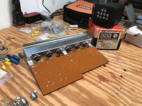
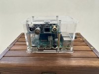
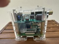
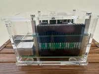
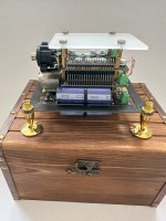
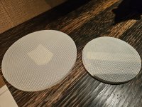
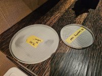
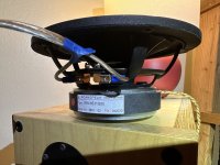
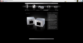
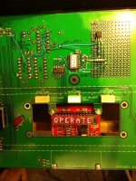
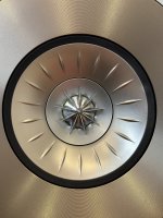
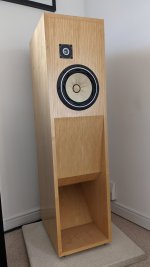
Design and optimization of waveguides was done with Fusion 360 (modelling) and AKABAK (simulation). The loudspeaker looks like this:
1707044535211.png
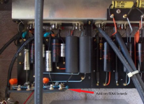
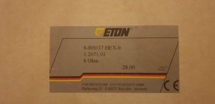
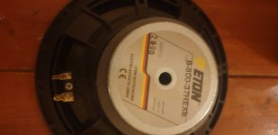
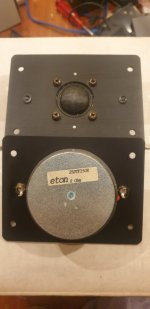
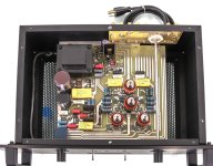
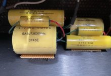
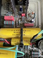
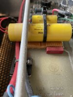
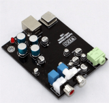
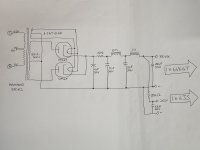
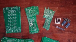
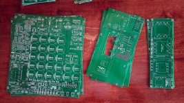
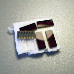
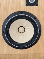
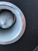
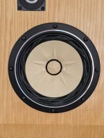
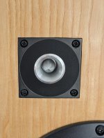
It uses the bliesma T25B, Kartesian Mid120_vHE, and Kartesian WOM300_vDIY. Waveguides are 3D-printed. Cabinet is 25mm MDF, 30mm for front baffle. Internal bracing is 16mm MDF. Amplification/crossover is hypex FA123. I also have a capacitor on the tweeter and two passive notch filters on the midrange (which reduces distortion in the passband).

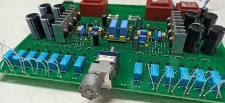
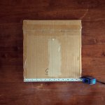
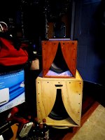
Measurements were done with 16ms gating (62.5Hz resolution) and there is thus no data below that, so what you see below that is interpolated and almost certainly wrong. Furthermore 1/24 octave smoothing was applied, as the mid-high frequencies are a little too wiggly to easily read without it. Note that the image above is not representative for how these measurements were done, that image is from a measurement session in early autumn.
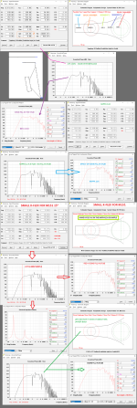
Spinorama:
1707044594759.png
Horisontal radiation from 70Hz:
1707044606099.png
Vertical radiaation from 70Hz
1707044614308.png
Some off-axis angles normalized to on-axis. 160 degrees was selected as that is where the woofer shows the strongest rear attenuation:
1707044626228.png
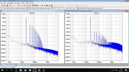
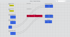
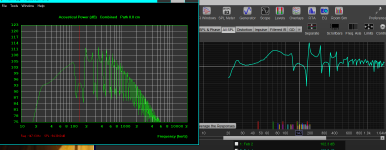
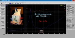
Finally, here is a comparison of the loudspeaker simulation (left, only simulated up to 5kHz, vituixCAD makes assumptions above that) and the measured sample (right):
1707044785758.png
The agreement between simulation and reality is remarkably good!
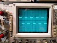
Finally, I have been listening to it for the past two days and adjusting a bit to taste. Here are moving mic measurements from my room, ~2m distance, no EQ/correction applied:
1707045299359.png
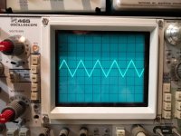
Overall I find it a bit bright and lacking bass (which makes sense, it's designed to be used with subwoofers). Due to my relatively short listening distance and the output capacity I've taken the freedom to increase bass output a bit, as well as use peak filters on the 102Hz and 135Hz resonances. I've also brought up the lower midrange/upper bass slightly. It now looks like this:
1707045445122.png
I find it enjoyable, but am experimenting with a -1 to -2dB high shelf filter, as it still sounds a little sharp at times.
If I were to build it all over again, there are changes I would make, but overall I am very happy. Feel free to ask any questions!

For Sale UK: Fostex FE208e∑+ FT96H in Dallas II cabinets

All working perfectly and just one mark on one of the tweeters as shown in photo.
Collection only if you want the complete speakers (can demo on collection of required), or I'll remove and send the drivers (I still have the original boxes) if you pay the postage.

£500

Attachments

  • PXL_20220911_125210939~2.jpg
    PXL_20220911_125210939~2.jpg
    244 KB · Views: 239
  • PXL_20220911_125108427.jpg
    PXL_20220911_125108427.jpg
    430.4 KB · Views: 228
  • PXL_20220911_125018289.jpg
    PXL_20220911_125018289.jpg
    451.8 KB · Views: 208
  • PXL_20220911_124918310.jpg
    PXL_20220911_124918310.jpg
    384.8 KB · Views: 198
  • PXL_20220911_124857565.jpg
    PXL_20220911_124857565.jpg
    436 KB · Views: 196
  • PXL_20220911_124847731.jpg
    PXL_20220911_124847731.jpg
    574.7 KB · Views: 222

Studiomaster Trilogy PSU

(orGreetings.

I've acquired a Studiomaster Trilogy 206 Mixing Board which has a PSU that is designed to be able to work both 240V and 120V. I have no intention of ever going to non-US locations where 240V would be used--so I'm looking to streamline the PSU--it is bulky, heats up considerably, has flimsy wiring and introduces noise when within 3 feet of the mixer itself.

To be up front, I have really no electrical training--so I'm at square one. In my head, I'd like to have a simple AC to DC converter (I think these are called rectifiers?)--as part of a simple PSU--the kind we get with our laptop computers.

The board requires 48V (for phantom power) and +/- 17V lines, along with a ground. It has a 5 pin input/output to the back of the board--which runs to the external PSU (heavy/bulky) where the actual power switch is located. I've looked for a 5 pin adaptor with a rectifier for AC to the required DC voltages--but no luck. I already contacted Studiomaster and they no longer sell these old PSU. I've asked a local engineering school and separate electronics shop but they said they had no interest in working on this. Makes me wonder if there is something really difficult or unusual about my request. I love the mixing boards--I actually have another I picked up which has no PSU--hence my idea to create one (or better yet, be able to simply purchase one).

I've attached a schematic if it might help. My preferred solution would be to simply have a three prong insert and on/off right at the back of the board >>rectifier (like the laptop cable/box) >> standard US AC outlet. Thanks in advance for suggestions!

Attachments

Audiolab M-DAC+ thoroid info

Hey guys,
sorry if this already has been discussed. Got M-Dac+ which wouldn't start, found that the problem whic was in the thermal fuse which is sticked to primary windings.
Does any one has any info on secondary windings voltage and current requirements? While drilling of the epoxy filling of inside kern, managed to damage some of secondary windings. Only clue I have is the resistance od sec. windings:
Orange - Orange 0.9 ohm
Violet - yellow - Violet 2.2.ohm
Red -Red 0.2 ohm
Originally transformer is Noratel TI-149(?)
any comments would be appreciated

IMG20240128171621.jpg

For Sale $75 new 4x Mundorf MCap Supreme EVO 0.47uF 1000vDC

I ordered these thinking that they'd have the same footprint as the Mundorf MCap Supreme (non-EVO). Rookie mistake.
I need AA battery shaped caps, these are wider and shorter.

Link: https://www.hificollective.co.uk/content/se-050-047uf-1000vdc-mundorf-mcap-supreme-evo-capacitor

asking $75 for the set of four
I'm thinking $17 each plus $7 USPS Priority contus (international shipping okay, cost would increase)
paid $24.23 each, but I know I gotta take a hit for not measuring twice

Will ship with same packing materials as I received them in.

Paypal preferred

Attachments

  • IMG_5447.jpg
    IMG_5447.jpg
    248.5 KB · Views: 72
  • IMG_5445.jpg
    IMG_5445.jpg
    345 KB · Views: 76

Cheers from the Wild Wild West!!

Hey guys! Excited to be here. Have spent 15+ years on the Car Audio forums. And have ended up on this site more times than I can count in my quest for knowledge. So figured I'd join!
I've build a few home speaker's. With the empty nest, is time to build some more. Currently jamming a Scan/Seas combo for my reference monitors. The DD is whole other story. Also currently building a system in my 65 Mustang.

Love all the collective knowledge. I look forward to being a contributing member. Cheers Jared
Projects by fanatics, for fanatics
Get answers and advice for everyone wanting to learn the art of audio.
Join the Community
507,635
Members
7,881,636
Messages

Filter

Forum Statistics

Threads
405,926
Messages
7,881,636
Members
507,635
Latest member
tom.mccann