To earth or not to earth power amp chassis?

Hello all and Happy New Year.

To earth or not to earth power amp chassis?
That is the question.

The most common way to implement safety ground for power amps is to use a ground lifter consisting of antiparallel diodes and a resistor.

On bonsai's brilliant writeup ground loops he says;

ground lifter.png


In a few countries in europe there are no grounded sockets in living areas.
There are only grounded sockets in wet rooms like bathrooms, kitchens, basements and outside.

So my question to all your knowledgeable people here.

What is the best practise with regards to grounding ( not grounding ? ) the chassis of a power amplifier that is connected to the net without a grounded socket ( no live, neutral and ground, only 2 live connections )

socket.jpg


thank you
rebone

Simulation of the JE-990 OP Amp By Deane Jensen

The JE-990 (990) OP amp by the late Deane Jensen is an impressive piece of engineering. I was highly impressed when I first read the AES article:
http://www.technicalaudio.com/pdf/J...ted/Jensen_JE-990_opamp_JAES_reprint_1980.pdf

and the application note for the LM-394:
http://www.ti.com/lit/ds/snls385a/snls385a.pdf

http://pe2bz.philpem.me.uk/Parts-Ac.../AN-222-SuperMatchedBipolarTransistorSets.pdf

I still like the JE-990 to this day.

Jensen is known for their audio transformers and some background about the company and founder is given here:
http://www.iso-max.com/history/

The 990 was first described in 1980 as a public domain design in the AES Journal:
"JE-990 Discrete Operational Amplifier"
JAES Volume 28 Number 1/2 pp. 26-34; January/February 1980

It was designed for use with Jensen transformers, and has found it's way into many Pro-Audio applications. It is a fairly standard OP amp topology, diff pair input loaded by a current mirror, standard VAS with a Beta multiplier, Baker clamp, pole-zero Cdom compensation, and additional HF compensation on the emitter resistor. The LM-394 Supermatch Pair transistor is used in the diff amp which provides low DC offset, low noise and distortion. It is essentially a low power amp that will easily drive 75 ohm loads.

The LM-394, current mirror load, Beta multiplier, Baker clamp, and pole-zero compensation were all innovative for the time.

John Hardy is probably the best known supplier of the JE-990, and also produces several pro-audio mic preamps based on Jensen transformers and the JE-990. He has some nice documentation with the JE-990 schematic here:
http://www.johnhardyco.com/pdf/990.pdf

http://www.johnhardyco.com/pdf/M1M2M1p.pdf

Edit: Why is it that only the first post can be edited? I'd like to fix the broken links here.

ADCOM Opamp & Semiconductor Replacements

Attached is a compilation of replacement parts applicable to ADCOM products. Thank you to Jim at ADCOM for your help.

Most ADCOM opamps are Linear Technology and the parts shown in parentheses are generally equivalent or better performing types.

Rick

Attachments

  • Like
Reactions: K-amps

Unobtainuim: digital x-over PC card

Thought:
With modern PC/PCIe (Thunderbolt 3, 4 interface, notwithstanding) technology, (Lenovo ThinkStation P520 is PCIe 3.0 and has Thunderbolt 3 GPIO port)
Internal PC Digital-domain crossover card;
parametric/"Q", phase adjust (tight enough for HF, MF, LF, SW driver offset)... with or without SPDIF/analog output...
Considering that most consumer-level audio is still 16/44... should no longer be Unobtainium.
... just a thought
Aside: will also be ripping DSD and/or DVD audio tracks to my music library... Terabytes of storage real estate, on NVMe drives... long gone are my 286/MFM days...
have long-since migrated to Zorintopia (17) - Ubuntu 22.04
fwiw

Big upgrade

I just moved across the country and had all my stuff ( stereo included) sent in a Pod. It was right in the middle of the big cold spell we had a month back. Well when I get it all unpacked I notice my cartridge no longer is in possession of a stylus. Cantilever is there but no stylus. Its a Dynavector 20X-2. I sent it to VAS in New Jersey to fix it. He replaced the cantilever with a boron one and a micro ridge diamond. I drove over and picked it up and when I got home I dialed it in and settled back for a listen. I was simply blown away by the improvement. It was a lot like the change when I swapped out my resistive volume control for an autoformer. More detail. Transient response was faster with better defined edges. Richer tone. I stayed up for hours playing records. I couldn't stop. It cost me $450 to have it done. And it was worth twice that much money IMO. If anyone needs their Aluminum cantilevered cartridge retipped go for the Boron. If it is anything like how mine turned out you will be thrilled.

Jeff
  • Like
Reactions: Netlist

Seeking suggestions or plans for tall narrow speaker cabinets for Tannoy Gold 12" Monitors

Hi DIYers,
I'm looking for advice and/or plans for enclosures for the 12"Tannoy Gold I inherited.
Hesitating between a simple horn design and ported cabs.
The issue with the horns is that the ones I have found are wide.
I'd like something that sort of hugs the drivers.
Curious to see what people have built.
Thanks in advance for sharing your experience,
Daniel.

Some ideas below:

Screenshot 2024-01-29 at 8.04.03 PM.png
.
Screenshot 2024-01-29 at 7.49.35 AM.png
.


The GRF is courtesy of Hans on the Tannoy Groups.io group, but the minimum width he recommends is 25.5 inches.
Screenshot 2024-01-30 at 6.10.53 PM.png

how to diagnose the component that blows a speaker (amp?) Nakamichi PA5, CA5, Infinity Modulus

hi,
I have the following setup:
preamp: nakamichi CA5
amp: nakamichi PA5
speakers: infinity modulus (1990)

recently one of the infinitys burned down, and I had it recoiled by a local guy who has been doing this for 30 years.
after 2 minutes of playing... it burned down again.

now, I'm suspicious that there might be a problem with my amp, or preamp. and I want to make sure it will work, as the guy who recoiled it was more sad about it than me (the guy takes pride in his work)

I tried hooking a different speaker to the amp, and it produces sound as it should, but I only had it hooked up for a few seconds to make sure that it still produces sound.

I tried measuring DC voltage on Amp Output and its about 25-30 mV on idle, but it goes up to 100mV when I play some music, but I need to double check that, since the measurement was done while the whole thing is still in rack, and wasn't accessible as it should, so there might be a measurement fckup on my part.

DC voltage on Preamp output is below 10mV, but also, I'd like to have another go at measurement (Get a new multimeter, and measure the amps, as attm, I'm getting 0.00 mA on both amp and preamp)

I'm not sure what else I can do to make sure that the Amp/Preamp are in working order.

the amp and preamp are 100% original and mint... and don't want to tamper it unless I'm sure it needs tampering.


please refrain from: have it serviced comments. Comment only if you actually know something about servicing and electronics.

Mark Levinson No39

Hello,

I have a defective Mark Levinson No39 that I bought as defective. Unfortunately, both transformers were defective and one is unfortunately no longer available (currently runs on a laboratory power supply so that I can at least test something to see whether it is still worth repairing). I have exchanged all electrolytic capacitors because they have expired, which apparently happens often with this series.
I now have the problem that one side is much quieter than the other. Maybe someone has a tip? The device is really stuffed with components. You can't adjust the balance here, can you?
Another problem is that the sound is choppy over spdif.

Best regards

Mario

Qts in OpenBaffle - How low can you go?

I gather that for bass extension, a fairly high Qts of around .7 is important in an OB. However, I keep seeing recommendations for drivers with rather low Qts, say around .2 to .3 in OB application (Fostex especially).

Assuming a bass-augmented system with an active crossover goal of about 200 Hz (150 would be better) and an OB size of about 20"-24", what kind of Qts value could one get away with, say for a 8" driver? Is there a tool to help determine this that includes the Qts factor as well as cone size?

I'm having a lot of trouble finding many examples around 8", at least 90 dB (SE tube friendly), inexpensive (under $100 each) with a higher Qts and with a good reputation for sound quality. However, if I could get away with a .3 Qts, that opens up the field a lot. If not, it looks like the Betsy is the best option so far but I would like a few more options to choose from if possible.

I'm starting to think that maybe a smaller driver would be okay too, but power handling for a largish room has been a concern of mine. Dispersion seems adequate on a 8" for me so far.

Hafler P-7000 same as the 9XXX series

Does the Hafler P-7000 shares the same topology as the 9XXX series ?

The reason I am asking is becasue you can find a P7000 for ok money, around $200, the Hafler 9XXX series are getting expensive with time


http://tolisdiy.com/2020/10/08/hafler-9505-9300-power-amplifiers-repair-and-measurements/

Attachments

Wonderful CD Player needs a new home

I have an AH! Njoe Tjoeb 4000 CD player that my wife and I purchased in 2004 for >$1000! It has always provided wonderful sound until recently when the audio output died. I contacted the vendor (Upscale Audio) where we purchased the unit and they suggested that it could be a tube issue. I purchased new tubes which -- unfortunately -- failed to resolve the issue. I would hate to see this excellent machine in the trash heap, but I don't have any background or experience in DIY audio equipment.

I would be most pleased to offer it to someone who could possibly resuscitate the unit and would only ask $200 to cover the cost of the new tubes (I will also provide the old tubes) and my shipping expense (from east coast US to elsewhere within CONUS). Please let me know if you'd be interested. Thanks

Its a Ground Loop question

Hello
I have a tpa3118 amp fed by a laptop running Daphile music server. Quality from the headphone output is just tolerable into amp and wharfedale 9.1s.
Problem came when I tried to use the same PSU. for both amp and laptop. Now I have got ground loop noise as laptop boots.
The question is will a ground loop noise isolator filter for 3.5mm aux cable help and will it sap the quality even further.

Wiring subs in bridged parallel - no "thru" connectors on cabinets

Hi all,

Am hoping to run two custom built (not by me) subs in parallel whilst bridging my amp so i have enough power. Problem is, the person who built them just put basic NLT4MP connectors on the back so there's no built in "thru" option for parallel. i have been reading through forums and the amp manual and think i've worked it out but want to double check before wiring it up.

Equipment:

2 x Fane Colossus 18XB drivers (1 per cabinet) (8ohm)
1 x Crown xti 4000

the crown speakon outputs are wired in parallel to the binding posts so my plan is:

1x cable with speakon connector wired 1+/2+ plugged in to CH1 of amp speakon. this then plugged into one cabinet wired at other end with 1+/1-

1x cable wired across the red binding posts and plugged into other cabinet with 1+/1-

in my head this should now give me 3200W spread across both subs, allowing me to run them up to their full 1000W rms.

Please let me know if this'll work and whether there is a better way to do this.
In the long term i plan to cut larger holes in the back of the cabinets and install proper speakon plates with through outputs. Photos below for reference

IMG_1048 copy.jpg
Screenshot 2024-02-17 at 17.39.07.png

fixed bias problem / question

I'm having a biasing issue in my Marantz 5 amp - I had a power supply cap go, and did 2 replacements. Now, I note then when I adjust one of the bias pots up (or down) the bias on both tubes goes up (or down). Used to be if one was adjusted one way, the other would go a little bit the other way, and this is how it still is in the other monoblock.


The only changes I made are 2:
replace a 20uf segment of C16 with a 20uf 500 v cap as the specs call for
replace the string of electrolytic at c15 with a 30uf 600v cap. I know the specs call for 6uf 600v.

Any thoughts on why increasing the bias at either bias pot is increasing it at both tubes? (hopefully not a short somewhere). It has me worried that something is amiss.

I've attached a schematic.

Many thanks!

Attachments

"Bigun's TGM8 with single Supply" Revisited

Dear friends,
Almost ten years back, I started a thread "Bigun's TGM8 with single Supply", https://www.diyaudio.com/community/threads/biguns-tgm8-with-single-supply.250380/ . Post #21 contains the final circuit.Three of our members constructed that amplifier with good reviews. After seeing lineup's 6Tr Lateral amp, I wanted to try my hand again.
The result is as below.

I retained Q-1,2&3 and the circuit around them same. There is a good improvement in Distortion and its profile.

Taking the guide for Dummies of minek for olg, I followed the method religiously and the result is as below.

I require help in improving the Gain and Phase margins. The .asc files are enclosed.Retro TGM8 with Lateral & TPC OLG.pngRetro TGM8 with Lateral & TPC THD.pngRetro TGM8 with Lateral & TPC.png

Attachments

Aavik I-880 by Audio Group Denmark amplifier board design question - Class A or Class AB??

Hi all,

I have had a chance to attend PAF convention where I gave a listen to this amplifier by Audio Group Denmark, and in my opinion it sounded better then all others. Official website has few pictures of the inside and describes it as Class A, but only biased when needed. To me the board looks like Class AB, just overbiased. Wondering if it is possible to determine such things from the picture of PCB?

Attachments

  • Aavik_880_17_ClassAOutputStagePowerSection.png
    Aavik_880_17_ClassAOutputStagePowerSection.png
    267.1 KB · Views: 273
  • Aavik-IntegratedAmp880-TopFront-RightSide-Cutout-DESKTOP.png
    Aavik-IntegratedAmp880-TopFront-RightSide-Cutout-DESKTOP.png
    403.7 KB · Views: 257

Denon PMA-S10 Mk II : MC/MM switch

Hey everyone,

After struggling to isolate a phono issue for a while, it turns out the MC/MM selector switch on the back of the amp is semi-knackered.
As I do not have a service manual for the amplifier, and google is coming up blank, could someone steer me towards a replacement for this switch ?
I don't want to do any mechanical mods to the chassis. The last resort is trying to disassemble and clean the switch.

Thanks, Pete

For Sale Hi. I do have parts for sale

Hi. I do have parts for sale such as MRS25 1% resistors by Vishay/Philips,Dale ,el.capacitors,PP capacitors,Mica capacitors, output transformers for tube amplifiers made by UTC,Stancor,Peerless,Acrosound,Chicago transformer Co. . Passive components are NOS . Some of transformers NOS too. NOS semiconductors -zener, rectifier diodes , TL431 IC . List would be too long so,Please,send your request and we can discuss details. Thank you for your interest.

For Sale MHDT DAC

MHDT Canary DAC with original GE JAN5670W tube, Sylvania chrome top 6SN7GTB, plus tube adapters for 6SN7and for other 9 pin variants ECC88 / 6922.
This uses the Phillips TDA1545A chips, link below to MHDT web page
Canary DAC
Comes with all original packaging, no power cord or inter connects included.
Teflon bypass caps added to output caps, can removed easily before shipping if purchaser prefers.
$400.00 plus PP fees and shipping, North America only.
20240204_071143.jpg20240204_071116.jpg20240204_071104.jpg20240204_071040.jpg20240204_071019.jpg

(R. C.) Clark Johnsen "The Wood Effect" book, clean copy inscribed by the author to John Marks

I HAVE CANCELLED THIS LISTING. THE ITEM IS NOW UP ON EBAY.

THANKS FOR READING!

JOHN

Clark Johnsen inscribed this copy of his famous book to me in the early 2000s, or perhaps even earlier. Clark managed to get his book published by Harvard, which always impressed the doo-doo out of me.

People want huge amounts of money for this book (I heard tell of a copy asking more than $800.00). But I'll settle for $120 (or reasonable Best Offer), and ship it at my expense in the US; foreign postage will be at actual cost.


IMG_0340 copy.JPG


IMG_0341 copy.JPG


IMG_0342 copy.JPG


IMG_0343 copy.JPG


Thanks,

john marks

thread for builds and audio musings

Hello,

I'll use this thread to post my builds and questions that I think are interesting. I just want to have a place to catalog my work and get some feedback.

My first posts on this forum were this build:
https://www.diyaudio.com/community/threads/sb-acoustics-2-way-with-passive-radiators.386597/
This build turned into the attachments below and were a 2023 Midwest Audio Fest Over $300 entry.

Overall I've been happy with the outcome. These are among the oldest speakers I've built that are still assembled and get use. I really like how small they are, it makes it easy to lend out to people to see what they think. As I've gotten more experience with measurements I've noticed some things that aren't right in my simulation so I may go back and re-do the measurements and filters.

1708107150166.png
1708107188957.png
  • Like
Reactions: GM and profiguy

Just another current feedback amplifier

I employed a few tricks such as improved wilson current mirrors, dual BC847/857 packages and CFP output with parallel BJT drivers so I can bias the output stage fully into Class A even into 16R. I also used the DC servo from hpasternack's A4. So far, I'm getting 0.0007% THD with 2Vrms input, ~7.8Vrms output into 16R at 20kHz and I'm quite happy with that result, but I was wondering if there was any way I'm missing that I could optimize this circuit further.

I'll post further measurements later, currently not home as I post this!

Attachments

  • image-30-2.png
    image-30-2.png
    40.4 KB · Views: 610

Martin Logan Spire defective bass amp?

Dear all,

I have a pair of ML Spires which I have enjoyed very much so far with my Octave V40 tube amp and always was astonished about the massive bass. Since a couple of days, one speaker lacks bass and exhibits a humming/plopping sound which definitely comes from the bass driver, not from the ESL panel. Unplugging the working speaker shows that only the ESL panel keeps playing sound, so I would assume a defective power amp for the bass driver? Also, the bass frequency settings (using the dial on each speaker) only changes on the working bass driver, the presumed broken one does not show a difference when I change values.
Are there any experts for Martin Logan here who have had something similar?

Cheers and thanks,
Philipp

PLC Super Distortion

Hi Guys.
A friend of mine gave me a PLC made 'Super Distortion' pedal that doesn't work.
After inspection, I found some wires that broke loose, a dried out electrolytic cap, and a shorted diode next to the DC in jack that looks like a Zener but with no number stamped on the body.
I googled the pedal in hope of finding the schematics, but nothing showed up.
Anyone who knows this pedal, I need your help.

2021 Unity Horn Kit

The last Unity horn kit that I did worked fairly well, so I thought I'd try this again.

40021357141_5cd391a8b1_b.jpg


Back in the day, Richard Clark was a big inspiration for my projects. He wrote "When we develop the perfect loudspeaker, it will be a single wide band point source. But until then, the best way to achieve that is with a minimum number of speakers.

This new design does a good job of attaining that goal, I think.


LDUcnN5.jpg


KZYmOto.jpg


Here's two pictures of the speaker. It's a work in progress.

jpeoa0P.png


Here's the phase and magnitured response, with EQ and xover. I think this is quite good, but it will get better. EQ settings are shown in the small boxes in the pic.

mQDPdUZ.png


Here's the polar response, with EQ and xover. EQ settings, again, are in the small boxes. I think this polar response is very good. The five drivers are basically behaving like a single unit. The curves are at 0, 11, 22, 33, 44 and 55 degrees.

baSBvqh.png


For comparison's sake, here's the Revel M16, which performs very well.

zpRa19i.png


Here's the response of the tweeter and the woofer array, using a single resistor and a 2khz high pass on the tweeter. As you can see, the tweeter is much MUCH more sensitive than the woofer array. This measurement is with no box, so output at low frequency is limited.

Simulation microphone in KiCad (spice)

I wanted to learn more about Microphones and I tried to recreate Pimped Alice: https://www.instructables.com/Modify-a-cheap-LDC-Condenser-microphone/

So I created it in Kicad and tried to simulate, but the output seems weird.

I currently have this.

I use sin input with 2.2k resistor to emulate the mic and +48V with 5.8k resistor to emulate phantom power.

What am I doing wrong?

1708469628673.png


1708469588889.png

Co Drive dual cone with dual VC

The patents have now expired on these.... http://www.codrive.com/
I got a pair about 16 years ago and they were really special. The tech and design is unique and really sounds like an accurate midrange driver from 300Hz all the way down to low bass circa 22Hz.
I crossed them over at 300Hz to a pair of Manger drivers which are still among the fastest (step response and CSD) and the blend was seamless.
I have emailed and called Ron ( the owner) but no reply.
Has anyone got a pair of these or know a supplier/dealer who still has stock?
1708259104177.png

Thanks
A.

STM32 USB to I2S UAC1 simple example not working… advices welcomed

I struggle since two weeks (hobby part time) to setup a working example of UAC1.0 USB to I2S - stereo 48kHz 16 bits on a stm32F4 discovery card (with CS43L22 CODEC).

I try to get the project developed as far as possible on existing code from ST:

  • STM32CubeIDE generated code,
  • The board Drivers/BSP code for the audio part.

I already know that the ST software is far from perfect, and that the implementation of Audio has been made overly complex / abstract / inconsistent. So no need to convince me of that fact: I know… I finally convinced that I understood it enough, and could leave with that.

But I don't succeed to get it working, and don't find why. The output is cracks + some part of (not correct) music. I checked with Music, and tests tracks with one stereo channel silent and the other with a 1000 Hz tone. On music, the volume on the streamer has an impact on the result:

  • low volume: one channel plays something and nothing on the other
  • Higher volume: more tracks and music+cracks seems to apppear on other channel

It looks like a problem with Buffer/DMA alignment. Channels mismatch, Main and Least significant bytes issues ?

I have the record and playback example working, from USB board. I normally use the same BSP and board drivers code. The I2C and CS42L22 configs are the same. The configuration of the I2S and associated DMA look the same…

In debug mode, I looked at the buffer values, with one channel active and the other with tome, and it looks correct. Pattern of values around 0 for the silent channet (0x00, 0xFF, 0x01…), and logically changing values for the tone.

I tried to modify the Sync function in usbd_audio.c to start playing the music when buffer is half filled instead of when buffer is 100% full and write pointer rollback to zero (which means that the USB is writing in the buffer just ahead of the DMA reading, seems…).

I looks at the HAL_init (mine generated from STM32CubeIDE, the other from the example), and they look similar, except for the prefetch which is enabled in my code, and is not in the ST "record and playback".

Would those symptoms trigger some thought about things to checks, or some corrections to make in the ST code that could result in that?

Help welcomed. Must be a small mistake somewhere that I fail to see…

I also have another issue (hope independent), that when I connect the USB, the board is always seen correctly by the PC (EP0 working OK), I can start music on Foobar and it plays… but EP01 is not receiving data (at least not activated). After 2-3 attempts, then it starts and I get the audio stream activate the DataOut procedure.

Best regards,

JMF11


JMF

Need help deciding - Tower/Bookshelf Higher end Build

Hi all,

I'm wanting some new speakers for my main living area in my new house.
The room is about 60m2. I will be building a Full Marty sub with an 18" UM18-22 to handle the low end.

I was going to buy some speakers and auditioned some towers on the weekend, then i auditioned a set of B&W 706 S3 2 way bookshelf speakers.
I was very impressed with them. So it got me thinking, if im going to spend $3200 AUD on a set of bookshelf speakers, surely i can DIY something myself.

I was originally a bit daunted by the thought of a 3 way tower build, but if i have a large sub handling base, a bookshelf should be a bit easier to achieve.

So firstly a couple of questions.

In such a big room, would a bookshelf keep up? I hear a lot about needing towers to fill the room etc. Does this apply in this situation?
If I'm building a 2 way bookshelf, I can focus more of the budget on high end drivers, surely i can build something to compete with the B&W?

I've built a couple of speakers in the past, have all the CNC/woodworking gear/Umik-1, so i'm well setup to actually do the building, i'll just have a lot to learn about crossovers etc in the proces, which i'm looking forward to.

I can get access to SB acoustic stuff easily and was thinking of a beryllium tweeter and a satori midwoofer. But i don't want to get ahead of myself yet.

What are your thoughts? Is a high end Bookshelf what i need?

Thanks in advance!

SD Card Player gets a Burson Audio Opamp

Months ago I received a Kind invitation from Burson Audio to try one of its discrete opamps, the ViVid V6 which I accepted.
I am used to discrete outputs since more than a decade I use a differential JFET zero FB amplifier from -ECDesigns- on several of my DACs (including one of my main) and players, and which has a smooth, refined and ellegant sound presentation whereever I use it. In fact, since then I have not played with opamps.
But recently, having upgraded my OTARI MX5050 to its highest performance I want to improve the critical Q501 equalizer amp, a JRC2043DD if I remember correctly. Unfortunatelly, the DIP8 adaptor socket there is very worn out and I had bad luck with my programmed opamp (2043; LN4562; OPA2064; Burson) comparison....I have to solve this issue ASAP.

Fortunatelly, I have here a humble but well built SD Card Player of Chinese Origin, a HiFi360.cn machine, with two SD Card slots and which has dual PCM1794 DACs (IF I remember correctly) had a passable sound in stock version and a competent Headphone out.
Of course, it did not stay in stock version for very long....I list below the upgrades which made it a very decent (as My Mom says) player...

-Reicherts Bifilar Current Baluns on AC input (varnished with Heavy Duty Varnish), and between PS caps and Voltage Regulators, both to Digital and to Analog (on PCB bottom) sections: 4 in total.
-Replacement VRegs for teddyregs, due to space cosntraints. The Heatsinks occult the former.
-Precision Clock.
-Dedicated 5V SPDIF out, to be used as transport with Elektro-optik connection to an outboard DAC.
-Many other caps, Pana FM and Rubycon Z on the output section.
-OPA2064 in class A, 3 in total: 2 for the stereo unbalanced out and one for the Headphone out, which receives the signal from the former.

The upgraded "Baluned" Regulated supply took it to a level where I could use it as only source for a whole week during my recent holidays, using my Beyerdinamic DT990 PRO.
I chose the OPA2064 years ago as it is a good allrounder without any "outstandings" but with many "goods" and "very good", especially on bass-midbass, warmth and color presentation that make me able to listen for prolonged time without irritation and fatigue. This player is really nice in its present condition, equally able with Classical and Jazz.

I swapped the Headphone section opamp from OPA2064 to Burson Audio V6 Vivid very easilly, though I consider that the pins that come with the unit are slightly thinner than what I am acustomed to. Looked fragile to me so I was careful.
Luckily, the overall tonal balance of the Burson mirrors the one of the OPA2064, which is no surprise you might say, as this opamp receives the signal from the previous unbalanced out opamps which are indeed OPA2064 (more on that later), yes but it sounds like the OPA on steroids, and after a week or of use I confirm that this is a significant upgrade, soundwise.
For example, the string attacks on Myaskovsky's String Quartets had more definition, bite and HF harmonics and the natural melodic curves are better delineated. I have a game which is called "where is the Viola" where one has to detect the sound of this (usually) "non-solist" instrument...well, here we can not only hear but follow the Viola's contribution. The sense of the recording space is more obvious and the decays of the notes is mopre prolonged. The OPAs produce a warm tone which is welcomed with modern digital recordings of chamber music and the Burson kept that warmth but reveiled more texture and nuances in the playing.
The attacks in percussion and bronze wind intruments is also more violent, richly textured and expansive in Mombasa's African style Jazz.
The scale of the sound presentation is increased and maitains a well kept order in Shostakovich Violin Concerto°1, also in big fff tuttis. The emotional tension of the long melodic lines is contagiously expressed. Overall, the Burson opamp made me see further into the music, with much more detail and tonal richness, better painting of the curves of the musical phrases, better enjoyment of the rithmic variation. to the point I am feeling I need to upgrade my Beyerdinamics...any advise is welcome.

But all of this improvement was with the signal fed from the previous OAP2064s....today I swapped the unbalanced out for LN4562, of which I have a bunch, and to my surprise the Player sounds now only a bit more "dry" or less warm, but not cold at all, which was my reason to abandon this opamp in the first place, but more and more detail is comming out, with the tonal balance now shifted towards the medium high and high frequencies, but with deep bass and punch when needed.
For example, in Ferenc Fricsay's 1954 version of "The Rite of The Spring" one is more able to folllow several richly textured instrumental lines at a time, which was previously very difficult, and the big strikes on the Big drum are very explosive with a long decay.
In Halley Cat from Nucleus the cymballs produce an all encompassing atmosphere around the playground of the trumpet and saxo, which was previously only guessed. I am having many gestaltic moments with this new combination, digging deeper into the music.

For those who know how to build one , a discrete output is very recommended. For those who can afford one (or 3) a Burson opamp will give you a much more Vivid (pun intended) musical experience.

This is my humble opinion.
Cheers,
M.

Attachments

  • BURSON AUDIO OPAMP (10).jpg
    BURSON AUDIO OPAMP (10).jpg
    200.2 KB · Views: 135
  • BURSON AUDIO OPAMP (3).jpg
    BURSON AUDIO OPAMP (3).jpg
    176.3 KB · Views: 130
  • BURSON AUDIO OPAMP (4).jpg
    BURSON AUDIO OPAMP (4).jpg
    159.3 KB · Views: 132
  • Like
Reactions: adason

Aesthetics vs acoustic perfection

Prevailing design these days is for the rounding over of everything on the front baffle, commonly blending into a waveguide as wide as the woofer. I find this unbearably ugly. While considering the details for my current project (small 10l cabinet nearfields) I'm wondering a) how significant a difference this makes and b) are there any other options to the rounded over and smushed out.

If i put a flat 45 degree chamfer around the baffle edge, instead of rounded edges, what is the actual effect it is going to have? a wobble in the response of maybe 1-2db? or is it something more magnificent? the somewhat famous LS35a design had a thick ring of felt around the tweeter to prevent the wavefront even encountering the edge of the baffle. Is something like this a valid option? You don't see this approach being taken these days. Another thing you don't see are those odd JBL accoustic lenses, even they looked better than waveguides, just.

I suppose i am hoping for a cool looking 3d printable metamaterial lens or something 😀
  • Like
Reactions: tubelectron

Best parts for a pair of neutral stereo studio monitors

Hello! This is my first time posting on this forum! I just finished a build for a personal set of speakers with a woofer and a compression driver with a horn attached which was very fun! I'm moving on to my next project where I would like to build a pair of studio monitors with a relatively flat frequency response, are there any well known drivers (tweeter and woofer) that anyone would recommend which would be a good fit for a reference pair? Thanks!

NAD 216 not coming out of protection mode

Hello,
I’ve recently bought a not working NAD 216THX for $110 the seller stated only relay not working needs replacement, I bought the amp knowing it’s not only the relay so not a disappointment, I did replace the relay with the exact same model not newer not older, and still nothing. All the caps seem visually fine so I’ve taken some voltage readings on some jumpers that make logical sense to me as I don’t know where to get started. Just some background I’ve never worked on amps or any kind of other electronics other than making some crossovers. Here are the readings I got (this is with black probe on chassis and red probe probing and AMP powered on)

Left Ch.

J303 -19.3V
J305 -61.9V
J307 0V (makes sense it’s GND)
J309 62V

Right Ch.
J304 -21.5V
J306 -61.7V
J308 0V (makes sense it’s GND)
J310 61.8V

+Vl 61.8V
+Vr 61.8V
-Vl -61.8V
-Vr -61.8V

I’ve also included some pictures of the AMP and I found the service manual but once again, don’t know where to start.
IMG_2398.jpeg
IMG_2399.jpeg
IMG_2401.jpeg
IMG_2402.jpeg

Attachments

Fostex 208 NS 8 inch driver cabinets, bookshelf size

Hi just wondering if anyone knew of a reasonable compact design for these speakers.
I previously had them in kirishima cabinets, but those days are gone of huge cabinets in my front room. so want to either build or buy some that are more compact. Appreciate the bass will be limited.
Thanks all.
Ps, if anyone has any cabinets that they are not wanting that will suit... Even better.

Technics SU 8080 Power Limiter Adjustment

Dear diyAudio Community,

I'm currently restoring my Technics SU 8080 integrated amp. I replaced all the electrolitycs, except the power supply ones, with Panasonc FCs, FRs and Elna Silmic2s. Cleaned allthe switches, pots and the speaker relay. Replaced half of the small transistors and all double transistors (2SA798). I know this issue had been somewhat discussed on Audiokarma forums before and no one really had an answer. I'm hoping, that since then, maybe, someone on this forum managed to actually get this power limiter boards adjusted according to the service manual or not.

I used the service manual for all the adjustments as follows:
1. Adjustment of (-B) voltage (negative power supply). I adjusted it to -44.5v according to the service manual with no problem;
2. Adjustment of speaker terminal DC balance. I adjusted it according to the service manual to 0mV, both in "DC" and "low cut" switch positions with no problem;
3. ICQ (idling of power transistor) adjustment. I adjusted it according to the service manual to 15mV with no problem;
4. Adjustment of power limiter is THE PROBLEM for me. I could NOT adjust these boards’ value according to the service manual at all. Whatever I do with trimmer potentiomenters R350 and R351 according to the service manual the waveform on the oscilloscope screen does NOT change all, niether its' vertical symmetry, nor its' amplitude.

So, has anyone actually managed to adjust this power limiter boards on the amp as per service manual or adjustment section Number 4?
What 1kHz test signal amplitude/voltage has to be applied to the amp input?
Do you need to connect resistive load (8 or 4 Ohms) to speaker terminals for this adjustment to be made? The service manual doesn’t tell anything about test signal amplitude/voltage or resistive load for this adjustment.

Sincerely,
Ivan Terekhov

β22 salvage

I received another bin of unfinished projects and I am trying to decide if I can salvage an almost complete β22 kit.

I do not understand the 3rd board for an "active ground" in the recommended set-up.
So, I would not want to use that.

I would most likely use 2 β22 boards for the amp and 1 σ22 board for the power supply.

The AMB website covers this option as follows:

2-channel passive ground.png


With this note:

"The wiring scheme for the 2-channel passive-ground configuration is shown in the illustration above. Of particular note is the ground-return wiring from the headphone jack. It should be connected directly to ground at the power supply (e.g., one of the σ22's "G" terminals). Do not connect the ground-return from the jack back to the β22 board. If the PSU is located in a separate chassis (as shown), then the ground return wire should be part of the inter-chassis umbilical cable."

I am a little confused because according to the schematic, signal ground and power ground are connected on the β22 board, so the ground return from the headphone jack is in fact connected to both signal and power ground. Why insist that headphone jack ground return be a direct line back to the power supply ground?

Can this be built in a more "normal" way without risking ground loops?

does Crossover fewer components better?

hi, I am new to Speaker crossover building, I have a set of speaker, it original crossover was quiet complicated. as shown in the attachment, it has many components, at the crossover point:2300hz.

When I frequency test each speaker driver, I realize the woofer driver has natural slop from 2500hz. so I simplified the crossover: leave the Woofer as it is without any crossover components, just add a 3.3UF caps to the tweeter, the new Crossover point is at 3300HZ.

When I try to compare both of the crossovers, the frequency almost the same, sounding almost the same in term of bass, mids and heights, and my simplified crossover feeling more sensitive, plays slightly louder.

so my question is:
When designing a crossover is it that true having fewer components is better so to preserve the speaker's original sounding?
do more components make the speaker sound better?

Attachments

  • WhatsApp Image 2024-02-20 at 17.45.15_43c3bbac.jpg
    WhatsApp Image 2024-02-20 at 17.45.15_43c3bbac.jpg
    371.6 KB · Views: 102
  • WhatsApp Image 2024-02-20 at 17.45.15_1481d49c.jpg
    WhatsApp Image 2024-02-20 at 17.45.15_1481d49c.jpg
    273.9 KB · Views: 100

Reviving a Mitsubishi DA R10

Cheers! I am seeking advice and guidance in attempts to restore a piece of analog audio history.
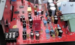
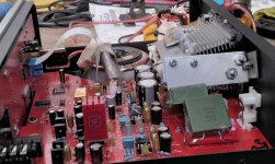
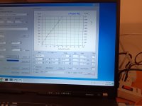
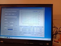
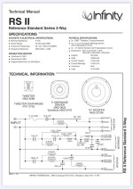
This Mitsubishi DAr10 receiver powers up passing a dim bulb test. However, relays do not click in; there is no sound produced in either channel. The preamp is OK. I can get a signal from the tuner with measurable output on REC OUT. Voltages in the amp circuits resemble what is shown at 'test points' in the SM.
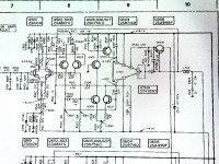
(see attached jpgs. I could not upload the entire SM or copy/paste from the PDF. )
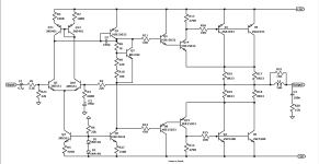
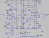
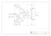
An STK1050 power IC produces output for each channel. Measurements for IC601/left channel were way off. Voltage readings on IC501 seem OK.

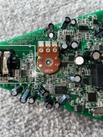
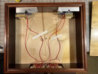
Additionally, the DC offset on L601 was in the order of volts! not mV! This could NOT be adjusted by VR601. Looks like the left channel either received a 'blow' or simply failed due to age. I removed the STKs, the impressive heat sink, and decades of domestic detritus. Also purchased new 1050s from SEMITRON on eBay.

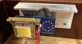
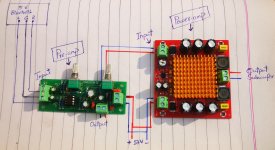
I came upon a clever way to trouble shoot an amp circuit like this:
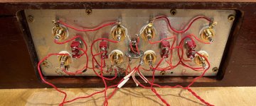
STKs removed, solder 4 resistors of equal value to jump in/out pin pads , gain down, preamp set to aux. My pairs are 1,4 and 0,7. — a Trouble-Shooting Setup…
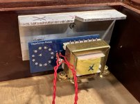
I was expecting the relays to engage ---no click... suggesting the HA12002 protection IC failed. Replaced it. (I was correct) Now, relays engage and the DC offset on L601 was reduced but still high and unresponsive to turns on the trimmer (VR601).

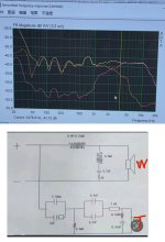
Taking a closer 'look' at the circuit involved w/DC offset --the N-channel JFET (Q601)-- and the trimmer responsible for adjusting DC offset; desoldered and tested - it is OK. Readings from the gate to R615, 614 did not compare to those on Q501. Since this gate is linked to L601 through C606, R612, R613 I pulled these out- tested OK- reinstalled --Presto! the trimmer now works (very touchy) to zero out the DC on L601.
P1010196.JPG
Must have been a 'cold' or oxidized joint. DC offset now acceptable.

Now, a return to comparing voltages between the two channels raises questions.
(pads 1,4 jumped; pads 0,7 jumped w/470 Ohm resistor)
Readings taken at the power IC terminals:
IC 601 terminals IC 501 terminals
pin 1 -3.5 V -.77 V
pin 2 -42.4 V -42.6 V
pin 4* 0.5 mV -0.2 mV
pin 7* 0.5 mV -0.2 mV
pin 8 ( not included )
pin 9 42.3 V 42.3 V
pin 0 3.48 V .75 V

Pins 3,5,6 not used in this amp design.
*(4,7 measured with Fluke DMM; mV setting w/an averaging function - these voltages tend to wander.)

Questions:
I can infer that there is a DC 'balance' within each channel, but what about between? Why is there that difference between the channels on the #1,#0 pads. Is this a problem? Is this a matter of incorrect idle current/DC bias?

Probing around the transistors with this Trouble-Shooting setup, I find the dc voltages between the two sides comparable until Q504/Q604, Q507/Q607 where a marked difference appears between the values @the collector of these transistors. The left channel, i.e., Q604/Q607 shows plus & minus 3.47V vs plus/minus .75V on Q504/Q507.
The schematic shows +1.2/-1.2 volts at the #0, #1 points which is the connection to these collectors. Maybe this is only when the STKs are in place. (I recall seeing this 1.2 V before the tear down on the 'good' IC501, right channel).


Here, my novice status becomes apparent.
Does this difference of about 2.75 V matter at all?
I can't explain why, at this drive stage, each side is not producing the same or comparable voltage. Indeed, what is the 'correct' voltage. I don’t see a way to adjust bias. Does this matter?

Testing Results:
A) the protection IC had failed; replaced - relays working
B) reflowing some components around the left channel JFET returned the DC
offset trimmer to 'functional’. DC offset now within specs.
C) the output module, IC601, had failed (via comparative ohms & diode testing) - I have two new STKs in hand
D) a difference of about 2.75V exists between the two sides with regard to DC being presented to the output modules.

Finally.....do you think I should simply install the new STKs at this point ?
Thanks for any feedback/insights.

Attachments

  • P1010197.JPG
    P1010197.JPG
    877.6 KB · Views: 84

  • Locked
For Sale Lang MosFET 20 Watt Class A Amplifier Boards 2SK134 2SJ49

SOLD I am selling these amplifier boards cheap as they are in unknown condition. They have been collecting dust in my closet for years . I found a spare set of output Mosfets I will throw in no charge. $30 plus $20.00 postage.

Attachments

  • 20240219_135932[1].jpg
    20240219_135932[1].jpg
    496.8 KB · Views: 270
  • 20240219_140642[1].jpg
    20240219_140642[1].jpg
    317.1 KB · Views: 211

TL072C upgrade for audio interface

Hi,

I am modifying the PCB of a GuitarPort audio interface. It's a pretty old product and they go for penny's on eBay. I got this one for 99p, so just fancied hacking about.

I've disassembled it, and it's got a tl072c right next to the guitar jack input, so I'm assuming that's the preamp and therefore will be the most important component to replace if I want to upgrade this interface? I've not modified circuits like this before, but I've got a lot of experience in SMD rework (component replacement etc).

4e0d28b4-2ae1-4cec-a9da-48c6e81d73b0.jpeg

Attachments

  • b326a96a-9d6b-43e3-be9c-2c0c278e3d85.jpeg
    b326a96a-9d6b-43e3-be9c-2c0c278e3d85.jpeg
    342 KB · Views: 94

  • Locked
Repairing Hakko Soldering Iron

Received about a year ago a severely defective Hakko soldering iron, only discovered it is severely defective long after the warranty has expired. When set to 850*C and has fully warmed up, no increase in temperature, the actual temperature of the tip is just under 150*C. 😳

Has anyone experienced this and successfully repaired this terrible deficiency?

Thanks in advance! 🙂

PS Why is it nothing of any reliability comes out of China? Rhetorical question, we know it is because no fully Communist country can manufacture anything like the Western world. No one made anything as good as the Dutch, Germans, and the Swedish, though might be a tad biased being Dutch, English, Frisian, German, Irish, Norman, Pomeranian, Prussian, Swedish, and Welsh. Ha.

uTracer6 GUI measurement accuracy issue

I have recently built a uTracer6 and noted a measurement accuracy issue using Ronald's GUI.
If you do a sweep with the (Va=Vs,Vg) the GUI seems to incorrectly report the test voltage for the screen current being measured.
The result can be large errors in the data collected for any (Va=Vs, Vg) sweep that involves a large test current delta between the anode and screen ports.
This is most notable at lower test voltages and high test currents.
For example if a high current pentode is measured in triode mode (think sweep tube) where a large delta is present between a high anode current and the screen current there can be a significant discrepancy in the test voltages used for the actual measurement and what voltage is reported by the GUI.
This can under some condition result in large errors in reported results.
To confirm this I measured a 50 ohm resistor on the anode port and then on the screen port.
With Ronald's GUI testing a 50 ohm resistor on the anode port and taking the reported test voltages and currents from the GUI, calculation confirms a 50 resistor is being measured.
Repeat this with the screen port and the GUI results suggest in error a 100 ohm resistor is being measured.

Note this seems to not be a defect with the uTracer6 hardware or firmware but only seems to be a issue with the present GUI.
I confirmed this by remeasuring the 50 ohm test resistor using the utMax GUI and then for both anode and screen ports the GUI returned the correct voltages and currents for a 50 ohm test resistor.
At this point I do not know if any other test modes other than (Va=Vs,Vg) on Ronald's GUI are affected on the uTracer6.

I have had a uTracer3+ for many years and not noticed this issue with the uTracer3+.
I do however use a older GUI version with my uTracer3+ than the latest version I am using with the uTracer6.
As well the uTracer3+ can not measure the high currents that a uTracer6 can and I only see this issue at higher currents on the uTracer6.

Attachments

  • Utmax.anode.50.load-correct.jpg
    Utmax.anode.50.load-correct.jpg
    401.3 KB · Views: 59
  • Utmax.screen.50.load-correct.jpg
    Utmax.screen.50.load-correct.jpg
    379.1 KB · Views: 66
  • Utracer.anode.50.load-correct.jpg
    Utracer.anode.50.load-correct.jpg
    385.3 KB · Views: 64
  • Utracer.screen.50.load-Error.jpg
    Utracer.screen.50.load-Error.jpg
    423.3 KB · Views: 76

For Sale Slagle Autoformers

I have to move, everything must go including my Slagle Autoformers.

These are the nickel core inductors mounted to a circuit board design by John Chapman with gross and fine adjustments as sold on the Intact Audio site. I have just gently put them in a nice box, wired with Alpha silver plated copper wire. You can have the Mahogany case or not, DIYers might like their own soldering done and the modules are easy enough to free from their home and ship. - buyer pays actual shipping from 49685 Michigan, USA.

$300.00

Attachments

  • full frontal.jpg
    full frontal.jpg
    305.1 KB · Views: 327
  • open box.jpg
    open box.jpg
    542.9 KB · Views: 345
  • module X.jpg
    module X.jpg
    397.6 KB · Views: 337
  • module O.jpg
    module O.jpg
    310.3 KB · Views: 322
  • back wiring.jpg
    back wiring.jpg
    348.1 KB · Views: 317
  • business of wiring.jpg
    business of wiring.jpg
    373.4 KB · Views: 318
  • knobs with bottom.jpg
    knobs with bottom.jpg
    303.3 KB · Views: 321
  • Like
Reactions: Sv00

Yaqin MC-5881A amplifier improvements

Yaqin MC-5881A

I bought one of these off ebay, and as soon as it comes, I'll trace the circuit, measure the voltages etc. and ask you knowledgeable chums for advice what components to change/improve. Not a major rebuild, just obvious mistakes if any and similar.

Anyone that already has the circuit, perhaps? This thing is also known as Yaqin (or Yaoin) MC-6L6 and Markhill MC-6L6.

MC5881a_mov.gif

Replace O/P transistors in Exposure IV power amp.....?

I have a sick Exposure IV, and am hoping someone can tell me what might replace the EXPP/EXPN o/p transistors please?
I'm aware that the MJ15004/3 combination can be used.

I'm 'informed' that the MJ21193/4 combo is also an option....and I'm interested in taking this further, as I have easy access to these 🙂
Can they be used, and would any changes to the circuit be required if I opt for 'em please??

I've attached a circuit diagram.

Attachments

  • exposure circuit IV.jpg
    exposure circuit IV.jpg
    184.5 KB · Views: 202

Modular AK4490 DAC

This is my modular AK4490 DAC that I made last year.
attachment.php


I started the design a few years back when I needed an optical SPDIF input for my TDA1541 DAC with tube buffer. Instead of buying something from China I decided to make my own. After all this is do-it-yourself audio, not buy-yourself-chinese-stuff audio.

First I made an integrated SPDIF board with AK4118 and STM32F030. Then I decided to add an AK4490 DAC. Then later AK4137 SRC. Soon I found a need to have a separate STM32F030 control board for other projects so I decided to make this more modular.

Now it contains 5 separate boards:
1. AK4118 receiver with optional AK4137. The board has coax and optical inputs as well as 1 optical output for SPDIF bridging. The board can output I2S via AK4137 or directly from AK4118 so the SRC can be truly bypassed. There is also an additional I2S input to AK4137 for an external USB-to-I2S board.
BTW fittingly the coax spdif input is based on Jocko's design (or rather advice to a fellow member) from 2005.
2. AK4490 board which is more or less according to datasheet with LM4562 as LPF Opamp. LT3042 regulators for VREFL/VREFR.
3. XLR "shield" for balanced output (2 LM4562 opamps).
4. STM32F030 control board with headers for HD44780, encoder, I2C, IR receiver and I/O.
5. Encoder board that has HW debouncers for encoder and switch. No SW debouncing needed.

The DAC can be powered by e.g. a SilentSwitcher with a battery pack (as seen in picture above).

The performance is close to datasheet level. THD is very close to the measurement limit of my setup. Here is the FFT spectrum for 44.1kHz/24bit SPDIF input.
attachment.php


Here are pictures of the DAC board and the XLR "shield".
attachment.php


attachment.php


Now all it needs is a chassis. Also the SW is still work-in-progress. But all in all a very educational project. Buying similar boards ready-made would have been much easier (and a lot cheaper!) but where's the fun in it.

Attachments

  • dac.jpg
    dac.jpg
    96.6 KB · Views: 2,493
  • ak4490.jpg
    ak4490.jpg
    111.6 KB · Views: 2,109
  • xlr.jpg
    xlr.jpg
    56.9 KB · Views: 1,875
  • SPDIF-Rout-ak4490-Rin-44,1kHz.JPG
    SPDIF-Rout-ak4490-Rin-44,1kHz.JPG
    357.8 KB · Views: 1,910

InConcert Miles 2022

Hello friends.

InConcert Miles 2022.
Project finished.

The original speaker was designed and constructed by Stig Erik Tangen.
You can find more information on the internet searching for "InConcert Miles".

Inspired by Hunsbedt Trebygg, "Karmann" from AVforum.ro, "BEF-NO" from AVSforum and "atledreier" from HomeTheaterShack".
I always had a weak heart for huge cone's.
Therefore I liked to built this configuration.
Here's the version in my own jacket.
Highs and lows designed and put in seperate cabinets.
I already heard the test installation here in my living room.
This sounds as music in my ears!
High-efficiency speakers with a wonderful depth, spaciousness and detail.
Also a very nice 3D sound production.
And now they are ready!
Fabulous!
This is sounding huge great open and very deep in my living room!
Very Happy with them.

Here some pictures during building process.

Attachments

  • PDFtoJPG.me-1.jpg
    PDFtoJPG.me-1.jpg
    346.2 KB · Views: 812
  • PDFtoJPG.me-2.jpg
    PDFtoJPG.me-2.jpg
    440 KB · Views: 831
  • PDFtoJPG.me-3.jpg
    PDFtoJPG.me-3.jpg
    344.4 KB · Views: 683
  • PDFtoJPG.me-4.jpg
    PDFtoJPG.me-4.jpg
    379.8 KB · Views: 664
  • PDFtoJPG.me-5.jpg
    PDFtoJPG.me-5.jpg
    377 KB · Views: 681
  • 0.1.jpg
    0.1.jpg
    408.3 KB · Views: 724
  • 0.2.jpg
    0.2.jpg
    427.6 KB · Views: 692
  • 0.jpg
    0.jpg
    421.2 KB · Views: 688
  • 1.jpg
    1.jpg
    589.8 KB · Views: 701
  • 2.1.jpg
    2.1.jpg
    454 KB · Views: 736
  • 2.jpg
    2.jpg
    573 KB · Views: 703
  • 3.1.jpg
    3.1.jpg
    393.5 KB · Views: 691
  • 3.jpg
    3.jpg
    676.3 KB · Views: 629
  • 4.1.jpg
    4.1.jpg
    372 KB · Views: 602
  • 4.jpg
    4.jpg
    258.6 KB · Views: 596
  • 5.jpg
    5.jpg
    589.7 KB · Views: 585
  • 6.jpg
    6.jpg
    446.6 KB · Views: 608
  • 7.jpg
    7.jpg
    387.8 KB · Views: 580
  • 8.jpg
    8.jpg
    381.1 KB · Views: 564
  • 9.jpg
    9.jpg
    543.9 KB · Views: 806

Need to replace Adam A7X transformer

Hello,

I've had my Adam A7X pair for about 8 years and one of the transformers just gave up. I sent it to my regular technician to try a recoil, but it seems like this is way more difficult than expected so I'll need to get a new transformer. The local distributor has changed hands a few times, so the new distributors don't seem too inclined to help much, since I did not buy the unit from them.

Would anyone know where I can buy a replacement transformer for an A7X?

For context, I live in Malaysia, so there aren't really a lot of options and will probably have to buy either recondition on ebay or from someone overseas and have it shipped.

Thanks in advance!

Subtracting error correction

Error correcting feedbacks compare the weighted output with the input and feedbacks only the error. It is possible to correct in open loop by subtracting/adding the difference with a bridged amplifier.
Here is another way of subtracting with very little feedback.
The error is already between the inputs, it is added to the negative input after inverting. By this what was lacking in the output is add. Due to slight feedback, it is amplified by only 1.057 to near perfect cancelation.
dist.noise cancelation.JPG

This is a lm3886 model with a gain of 26db. Stand alone, it has a noise of 5.5mv in 20-20khz BW. By subtraction, it becomes 32uv. This is 180 times reduction in anomalies. The circuit as is, is unstable as it also increased the frequency response.
In real world, using NE5534 as differential, it needed a gain of 1.31 for minimum noise of 120uv and reduction in gain to set it back 26db. A capacitor made the circuit stable.
lm3886 error subtract-1.JPG

Series capacitor placement

I’m going to apply a series capacitor tuning technique on my closed-box speakers. There is a confusion on the correct placement when there are examples with different locations.

Firstly, the papers such as Thiele, von Reckling- hausen, and SB Acoustic’s suggest placing the capacitor directly in series with the driver. However, some well-known speaker manufacturers such as Infinity, Wharfedale, etc. placed the capacitor in front of (before) woofer’s low-pass filter, according to the crossover schematics. And, finally, there’s a sense that the capacitor may be able to be installed at the speaker terminals. Thus, which one is the correct position?

Attachments

  • IMG_7864.jpeg
    IMG_7864.jpeg
    165.4 KB · Views: 85
  • IMG_7865.jpeg
    IMG_7865.jpeg
    25.6 KB · Views: 89
  • IMG_7866.jpeg
    IMG_7866.jpeg
    72.6 KB · Views: 117
  • IMG_7867.jpeg
    IMG_7867.jpeg
    142.5 KB · Views: 86

Hello from Tokyo

Seems like I have an account since 2021 but never posted anything yet !
So, hello, Seon, living in Tokyo !
I have been messing with electronic for a few years now, learning by myself while fixing recording gears for friends and a few junks I find in second hand shops from time to time.
This year I'd love to level up and become able to make my own circuits too !
I would love to build a little mixer someday as a centre piece for my homestudio.
Nice to meet you!
  • Like
Reactions: TNT

Measuring Fc and Qtc of a closed-box system

In several places I've seen the method described for measuring/ calculating free air resonance Fs and Qts of a loudspeaker driver. For example, see Section 1.1 of this article by Rod Elliott-

http://www.sound-au.com/tsp.htm

So my question is, can this methodology be successfully applied to a closed-box loudspeaker system? After building a closed-box system, I wanted to check that Fc and Qtc actually are what I intended them to be. I imagine this is something that quite a few other builders would like to do.

Thanks if you know,
Pete

Problems with a Class D amplifier System

Hello guys, I hope you are all doing well.
I'm new to amplifiers and sound systems so I don't know much about them. I'm building a small sound system for my room, this is the setup for just the subwoofer. I have purchased the bluetooth module, pre-amp and power-amp from AliExpress so they aren't of very high quality.
The Pre-amp and Power-amp run on 12 volts while the bluetooth module operates at 5 volts. The Power-amp is rated at 150 watts max. My Subwoofer is dual coil, 1.2 ohm (I guess it becomes 2.4 ohms when I connect the coils in series), and 60 watts RMS, 150 watts max.
I need your help with the connections. Here's how I did it:
The three wires from Bluetooth module (R G L) go into the Pre-amp, the output wires (two wires) from the Pre-Amp go into the input of the Power-amp. The two output wires from the powe-amp go into the subwoofer.
I'm feeding this system with a 12v 10A power adapter.
These are the issues I'm facing:
1. There is a constant noise in the subwoofer. When I disconnect the audio input wires from the pre-amp, the noise goes away. If I take out the pre-amp completely, there's still a buzz in the Power-amp.
2. The sound volume starts to fluctuate after a while. It goes up and down on its own.
3. Sometimes I hear ticking noises in the subwoofer, it's not clipping because I can hear them even when the volume is very low.
I'm attaching a rough diagram of these circuits. Please pardon me if I'm doing something wrong. Your help will be appreciated.

Attachments

  • IMG_20240217_142038_edit_507678371108470.jpg
    IMG_20240217_142038_edit_507678371108470.jpg
    314 KB · Views: 139

  • Locked
EV charging insulation transformer problem

it is out of audio topic but maybe some electrician expert can help me.
I live on Germany here we have 3 phase power star with center neutral to ground,each phase to neutral 230v and phase to phase 400v. max allowed current per phase 20A
unfortunately I have an electric car that can charge 7kw 230v 32A monophase no 3 phase
I could slavage 2 toroidal transformer 230v 230v 7kVA from solar inverter.
so I wired primaries in series connected to phase 1 and pase 2 they receive 400v, 200v each primary up to 20A
secondaries are in parallel they provide 200v up to 40A
electric car charges fine up to 24A but more than. that it stops because the voltage gore below 190v (sag from cables and toroids)
I am fine with that and at 24A all works fine.
To avoid the undervoltage cut off I added a third transformer at the secondaries of the 2 big toroids to increase the voltage from 200 to 220v
it is a 1KVA EI transformer 230v 24v 40A connected as autotransformer.
I get 220v the car charges up to 20A but if I increase the amps then the loading cable device (the one that tells to the car ar what amps it has to charge) makes a reset, screen goes dark and more strangely after a few seconds the 20A circuit braker at the primary (400v) side, trips. I reproduced this 3 times.
I suppose that maybe the loading cable device RCD senses a loss to ground, my EI transformer was lying on moist soil, I could understand a reset of three charging device
but why is the circuit brakes tripping?

hos is it possible that more than 20A are flowing for an instant? peak overcurrent?
Projects by fanatics, for fanatics
Get answers and advice for everyone wanting to learn the art of audio.
Join the Community
507,645
Members
7,882,592
Messages

Filter

Forum Statistics

Threads
405,960
Messages
7,882,592
Members
507,645
Latest member
Tahoephoto