Hello,
My latest preamp/switcher project and build. This pre offers all the normal functions you'd expect in a pre, along with a couple selectable features. The design and layout of the board was done by fellow DIY'er, jhofland. It is based on the excellent OPA1656 chip, and other support ICs along with a few TH parts, and external breakout boards for volume, selector and headphone. The PCB is double sided and turned out beautifully. It has a fully, self-contained and integrated PSU. No power brick required.
This project had it's roots in my desire to have a matching preamp, to mate with a recently completed
Modulus- 86 amp build.
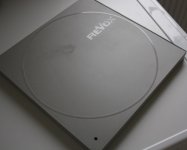
Latest Preamp and Modulus-86 amp.
As mentioned before, the guts of the pre is a double-sided preamp PCB. The design specs feature;
o - Based on TI's OAP1656 opamp chip.
o - Uses TI's OAP1637 fully differential chip.
o - Uses Analog Devices' MAX79220 headphone amplifier.
o - 1 balanced input
o - 3 single ended inputs
o - 1 balanced output
o - 1 singled ended output
o - 1 separate headphone amp
o - 1 subwoofer output w/selectable crossover at, 80, 120, or 200Hz
o - 1 12V Trigger out jack (3.5mm)
o - adjustable gain at 0dB, 6dB, or 12dB (onboard 4-pin DIP)
Other features include;
o - Use of small breakout boards for the;
(1) the volume control pot
(2) the input selector with LED KK connectors
(3) Headphone output jack
Micro-match connectors are used for connection from the main board to the above remote breakout PCBs.
o - All I/O is also available with the use of MolexKK 2 and 3 pin PCB headers.
o - All onboard and integrated PSUs. No power brick to contend with.
o - Integrated IEC connector on read panel.
Top/Bottom view of the PCBs;
Here is what the fully populated board looks like, sans the 5V power module.
The objective of this particular project was to build a general purpose preamp with the features I wanted, and more specifically be a matching 'mate' to my Modulus-86 amp. This, of course, would involve using an identical mini-ITX as pictured above. I like to experiment with new and different enclosures that aren't run of the mill silver and black traditional audio cases. Because of this factor, you're never sure if you'll be successful in getting everything installed in the same sized case. Hence the custom preamp PCB. The PCB is 140mm x 140mm. This doesn't leave any room leftover for other pieces you may need. I had a pretty good idea of what I was dealing with and other remote software module I was planning on using in the build. The PCB turned out great as fabbed by JLCPCB, and fits perfectly in my red case. This mini-ITX HTPC is available online
here at Amazon.
Using this type of unconventional enclosure general will require more than just drilling holes. There is a degree of case work that's required in the way of front and/or back panels. I have a 3D printer that works well for creating custom sized panels needed for converting a computer case to a useful piece of audio gear. And, you have to be prepared to modify your design as you go along.
🙂 This is a very challenging and time consuming process. And if you're a perfectionist well.....you know how it goes.
When considering the features I wanted in the preamp, I wanted to make it as flexible as possible, so that it could be used in various types of situations and enclosures. One of those features is the use of either; (1) RCA jacks that can be soldered directly onto the PCB, or (2) use 3-pin MolexKK headers on the PCB. The former would involve easier case work, as you could simply cut out a rectangle on the back panel and expose all of the pre's I/O more easily, while the latter could be used with casework that already has holes for the I/O. These are simple alternatives depending upon your preference and implementation. This feature is not available for the balanced connectors.
Here's an image of the various I/O connectors and footprint for the RCA jacks.
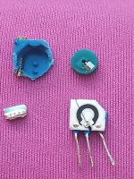
Another feature I like to have, and is on all late model PC cases - for about the past 20yrs - is the momentary on/off switch on the front or top of cases. To take advantage of such a switch you need some sort of low-voltage switch to trigger the mains, or simply act as an inline switch to a PSU. In past projects, I've used a small softstart switch (also designed by jhofland), that is ideal for a MO switch to turn on new builds. It provides for using a single switch, and even the Power and HDD LEDs also on the front panel of mini-ITX cases. I use these in almost all my projects over the past couple of years.
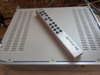
Remote low-voltage softswitch.
Also designed into this preamp are the breakout boards for the 3 operational features like; (1) Input selector, (2) volume control, and (3) headphone jack. Putting them on breakout PCBs allow for different mounting/placement options. The Micromatch (TE Connectivity) connectors and cables are used to connect them to the main preamp board.

Here are a few images of my build in process.
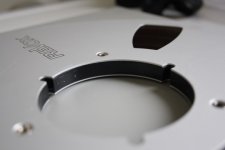
Final layout of the Back Panel. (4MM thick 3D printed)
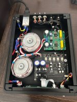
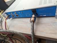
Fully wired up preamp.
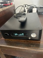
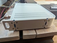
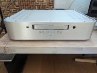
Fully finished and closed up preamp with smoked glass top.
The dynamic duo.
🙂
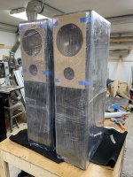
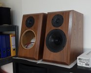
Temporary living room testing setup with vintage, HP-100 4-way speakers. The combo sounds so awesome, and the dynamics are really something you've got to hear.
If interested in the PCB board for this preamp and/or the low-voltage softstart board PM me for details.
Enjoy,
Rick
 20240224_144209.jpg130.3 KB · Views: 297
 20240224_144234.jpg204 KB · Views: 283
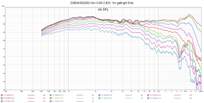 D2604 H0-90 gated.png75.7 KB · Views: 214
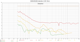 D2604 dist.png40.2 KB · Views: 187
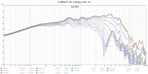 U18 H0-90 gated.png95.5 KB · Views: 184
 U18 dist.png66 KB · Views: 196
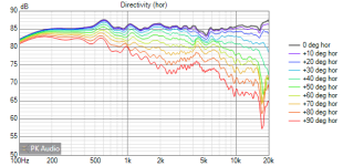 v2 Directivity (hor).png16.1 KB · Views: 186
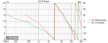 v2 GD+Phase.png8.7 KB · Views: 189
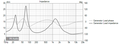 v2 Impedance.png8.8 KB · Views: 187
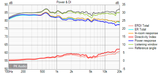 v2 Power+DI.png11.7 KB · Views: 201
 v2 SPL.png8 KB · Views: 259