Update ElVEEs Circlomos

Let's return to the discussion of the wonderful amplifier.

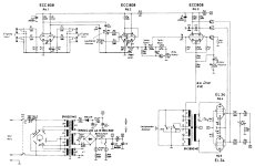
I tried to improve it using a simulator.

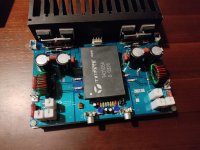
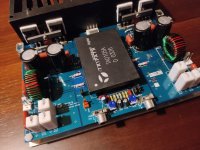
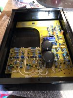
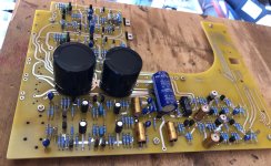
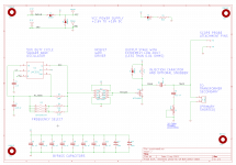
I used field effect transistors in a voltage amplifier. I equalized the current of the upper transistor of the voltage amplifier by adding an additional current source, and disconnected the quiescent current control circuit from the voltage amplifier. The coil in the differential cascade increases the gain without feedback by 20 db
  • Like
Reactions: stv

Single-stage active RIAA correction with second- or third-order Butterworth high-pass included

Hi all,

While thinking about ways to speed up the settling of a single-supply single-op-amp RIAA amplifier, see https://www.diyaudio.com/community/...upply-phono-preamp-design.413571/post-7702435 , I found a way to include a second- or third-order Butterworth high-pass filter. As it may be useful outside the context of single-supply circuits, I give it a separate thread.

When you just look at the topology and ignore the component values, this is a rather conventional RIAA amplifier (you could make it even more conventional by connecting R7 in parallel with C5, that doesn't matter much for the principle):

RIAAEV3tussenstap.png


Normally, C8 is used to cause roll-off in the subsonic region and the network R7...R9, C5, C6 realizes the RIAA poles and zero. In this case, however, I use C8 to realize the lowest RIAA pole at -1/(3.18 ms) and R7 to get subsonic roll-off.

Note that C8/C5 = 1000, meaning that without the subsonic roll-off, the DC gain would be 1001, a very ordinary value for a moving-magnet amplifier (1 kHz gain roughly 40 dB).

With everything ideal, at the value of the Laplace variable s where the impedance of C8 cancels the impedance of R12, the feedback disappears and the gain goes to infinity. This means that there is a pole at exactly -1/(R12C8), so if this has to be the first RIAA pole, one needs R12C8 = 3.18 ms. It's actually 3.196 ms in the schematic, pretty close.

The disadvantage of using C8 for the first RIAA pole is that C8, which has a relatively large value, needs to be accurate to get an accurate first RIAA pole. (C8 has practically no effect on the gain at frequencies much greater than 50 Hz, so its tolerance affects deep bass, but not channel balance.) The advantage is that you can include better subsonic filtering in the loop by adding two more resistors and a capacitor.

As an intermediate step, suppose you could add an ideal inductor with a huge value between the output and the negative input of the op-amp, chosen such that it resonates with C5 at the desired subsonic roll-off frequency, and that you chose R7 such that it damps the LC circuit to a quality factor of 1/2 √2. The subsonic response would then be very close to second-order Butterworth. That's because the gain of the RIAA correction amplifier is one plus the ratio of the feedback impedance to the impedance from the negative op-amp input to ground, and that "one" is quite negligible at low frequencies. Mind you, R8 and R9 contribute to the damping of the LC circuit, but not by much. You could also choose a quality factor of 1 and design the AC coupling at the input for the same cut-off frequency. The combined response is then third-order Butterworth.

Such an ideal inductor is totally impractical, but it can be approximated with a T network consisting of two resistors with values much smaller than R7 and a capacitor to ground at the point where they are connected, see this figure:

RIAAEV3.png


The transfer from the voltage going into R11 to the current coming out of R10 rolls off at a first-order rate from some very low frequency onwards, like would be the case with an inductor.

I haven't found any simple exact equations for any of the values except R12C8 = 3.18 ms. In fact, I've been very lazy and just calculated approximate values for the other components, and then used a pole-zero extraction program to fine-tune the values.

Regarding those approximate calculations:
R12C8 = 3.18 ms to get the first RIAA pole at the right spot.

The DC gain would be 1 + C8/C5 without subsonic roll-off, so C8/C5 = 1000 gives you a midband gain of roughly 40 dB.

At s = -1/((R8 + R9)(C5 + C6)), the impedance of the network R8, R9, C5, C6 goes to zero and the gain of the circuit becomes 1. As a gain of 1 is pretty close to 0, this must be close to the location of the RIAA zero. That is,

(R8 + R9)(C5 + C6) ≈ 318 μs

At s = -1/((R8 + R9)C6), the impedance of the parallel connection of C6 and R8 & R9 goes to infinity. The impedance of the whole feedback network remains finite due to the other branches R7 and R11, C7, R10, but it does get pretty large. That means the second RIAA pole must be close, so we get the extra criterion

(R8 + R9)C6 ≈ 75 μs

The (theoretical) inductance L is chosen to resonate with C5 at the required subsonic roll-off frequency and R7 is chosen to get the desired quality factor. R10 and R11 get convenient values much smaller than R7 with R10 also much greater than R12. We then have

C7 = L/(R10R11)

Best regards,
Marcel

Edits:
Input RC coupling
The RCR T-network that approximates an inductor actually approximates an inductor with inductance L = R10 R11 C7 and a series resistance of R10 + R11. At low frequencies, it stops behaving inductively, it just turns into the series connection of the two resistors.

As a result, one of the zeros of the high-pass filter that are supposed to lie at s = 0 actually lies somewhere around s = -(R10 + R11)/(R10 R11 C7). For the second-order cases, I have used the first-order high-pass at the input to cover this zero by making the input RC time constant approximately equal to R10 R11 C7/(R10 + R11), or actually to a more accurate value for the displaced zero found by the LINDA pole-zero extraction program.

For the third-order case, I have used the input RC coupling to make the real pole of the third-order Butterworth response, so I couldn't use it to cover the displaced zero. I used the output RC circuit in that case, or simply did not cover the zero. The effect of the zero not being in the origin is typically only seen below 1.something Hz anyway.

There is another zero not exactly in the origin, this is related to the + 1 term in the gain expression of a non-inverting op-amp amplifier. It is so close to 0 that I decided not to bother correcting for it.

Regarding the single-supply versions, the filter R1, C1 is meant to provide some power supply ripple and noise rejection. (Even though the single supply has to be regulated, some extra rejection is very useful at the input of an amplifier that amplifies hum frequencies hundreds of times.) R2 and C2 in series with the cartridge impedance also help to suppress supply ripple. The second-order versions have greater values of C2 than the third-order versions and therefore have better ripple rejection at the lower audio frequencies (such as 100 Hz or 120 Hz).

16 Hz split-supply versions
This is a version for split supply and 16 Hz cut-off frequency, see post #58, https://www.diyaudio.com/community/...rworth-high-pass-included.413649/post-7927611

sRIAA2_3.png


For the second-order version (values in parenthesis), the input coupling capacitor C2 can be replaced with a short circuit if you don't mind when the roll-off reduces to first order below 1.3 Hz.

This is a variant with 46 dB rather than 40 dB midband gain:
sRIAA56_46dBgain.png


Thanks to having R6 split into R6 and R0, the time constant of the input RC coupling network can be set more accurately without needing awkward values for C2. This was implicitly suggested by hbtaudio on another thread. Because of the high midband gain, the op-amp needs to have a fairly high gain-bandwidth product to get accurate RIAA correction (16 MHz gain-bandwidth product will give about -2 % error of the location of the second RIAA pole).

Finite gain-bandwidth product
See post #100, https://www.diyaudio.com/community/...rworth-high-pass-included.413649/post-7964481 , for some rough calculations on the effect of finite gain-bandwidth product of the op-amp.

From post #101 onward, Nick Sukhov points out that an amplifier with a high open-loop output impedance would result in a loop gain that depends much less on the RIAA correction circuit impedance. That's something to keep in mind when designing a discrete amplifier, you don't have the ability to choose a high open-loop output impedance when using op-amps.

Applying the subsonic filter to a discrete preamplifier based on the Hoeffelman and Meys configuration
The discussion with Nick and Chris about open-loop output impedances made me realize that the subsonic filter of this thread could be combined with a low-noise ("electrically cold") input termination resistance realized with a special feedback configuration that Dual already used in the late 1960's (CV40 phono section, see https://www.diyaudio.com/community/...o-input-load-modification.424717/post-7947176 ) and that was advocated by Hoeffelman and Meys in a 1978 AES article (Jean M. Hoeffelman and René P. Meys, "Improvements of the noise characteristics of amplifiers for magnetic transducers", Journal of the Audio Engineering Society, vol. 26, no. 12, December 1978, pages 935...939, see also Ernst H. Nordholt, "Comments on "Improvement of the noise characteristics of amplifiers for magnetic transducers"", Journal of the Audio Engineering Society, vol. 27, no. 9, September 1979, pages 680...681). The very first electrically cold resistance was made by William Spencer Percival and W. L. Horwood in 1939 as far as I know, but they used a different configuration and did not apply it to phono preamplifiers. See W. S. Percival, "An electrically "cold" resistance", The wireless engineer, vol. 16, May 1939, pages 237...240.

The schematics below show the resulting configurations. They are identical, but the left schematic is for people familiar with nullators and norators, the right schematic for people who feel more comfortable with high-gain twoports and op-amps. At frequencies well above 50 Hz, the input impedance approaches (R13 + R14)/(1 + R13/R12 + R13/R10). You can make this equal to 47 kΩ while using an R14 that is much greater than 47 kΩ, thereby reducing the thermal noise current √(4kTf/R) that gets injected into the input.

RIAAmetsubsoonfilterin1C.png


You can't do this with op-amps (not without floating supplies anyway) because op-amps lack the negative output that conducts a (signal) current equal but opposite to the current through the positive output. That is, you can make electrically "cold" resistances with op-amps, but not as shown here.

Document about dimensioning the circuit
The attached zip file contains a pdf document that explains step-by-step how the component values were found (section 2) and that presents a more accurate method than I have used (one that doesn't need fine-tuning with a pole-zero extraction program, section 3). It also contains a spreadsheet for the more accurate way to calculate the component values.

Deriving the expressions was a nice exercise, but I'm not at all convinced that my more accurate calculation is of any practical use. It can very easily lead to negative or complex resistances.
Attachments

PCB advice, Please and THANK you

I want to make an input selector, using Raspberry Zero and phono pre-amp, both jammed on a single board. Since I am IT guy, not an electrical engineer, can you PLEASE review my PCB design and let me know is this going to make it really bad and what should I change to make it work nicely?

This is a RIAA pre-amp part:
RIAA Part.JPG


This one is an input selector, controlled with Raspberry, with connectors for switch and display:
Selector Part.JPG


Here is the entire board, top side first:
Whole board - Top side.JPG


...and bottom side
Whole board - Bottom side.JPG


THANK YOU IN ADVANCE!!!!

Marin

Help DIY Subwoofers - India

The past two weeks have been a black hole of DIY subwoofer obsession. With high-end audio gear costing more than a used car these days, I’ve started thinking—why not build my own

I’m toying with the idea of upgrading to a set of identical DIY subs in near future may be in a year. Is it a great idea or a potential money pit? No clue. But after walking through endless forum posts and YouTube rabbit holes (mostly featuring folks who think Dayton is the only driver on Earth), I’m officially ready to consult the real gurus—you guys.

The bass battleground:
13.5 ft wide x 21 ft long x 10 ft high
Its a Acoustically Treated Room (Thanks to Anthony Grimani Videos), I have M&K S150 LCRs, SVS Bookshelf Surround and Subwoofer i have two PB 2000 (Not Pro) at rear and single Rythmik FVX 15 in front

Here’s my current state of mind:
  1. DIY subs: brilliant or bonkers?
  2. My woodworking skills are… let’s just say Sharpening the pencil .
  3. What good drivers are available in India? Dayton is everywhere, but I’ve got my eyes on Lavoce and BMS
  4. 18-inch vs. 21-inch: is bigger really better?
  5. WinISD is fun until it throws a “division by zero” tantrum. Can I really trust it to model things down to 20Hz?
  6. Driver shortlist so far: Dayton UM1,Lavoce SAN214.50 (Refered fellow forum mate!) & BMS 18N862
  7. Looks BMS is good.
  8. Sealed or Ported which one to go.
  9. And for designing Sealed do i need to depend Win ISD or i can go with the capacity details provided in OEM Site BMS says 150 Liter for Sealed Enclosure.
Goal: cinematic bass that punches you in the chest—just like the legendary JBL 4645C.

Oh, and fun fact—ChatGPT’s been throwing out suggestions like it’s got a subwoofer PhD. Honestly, it's like talking to an audio-obsessed buddy who never sleeps. 😄

Why isn't there any easy way to use TPA3255 in a car?

I've been trying to figure out why there's car amplifiers that use 12-16vdc and produce 1,000+ watts rms easily but there's no easy solution to power class d amps boards in a car? I want to be able to power some class d amplifiers that require 32-36vdc in my car. If a car amplifier can do it why aren't there any power supplies available to boost 12v to 36v for this purpose? The only things I've seen even close to working are the cheap boost converters on eBay, Amazon, and AliExpress but the quality, lack of directions, and even worse the believability of the specs are less than ideal. I would have tried them anyway if I thought there was a chance they would work without introducing noise or other headaches.

SMPS400A400 additional capacitance?

I plan to use a Hypex SMPS400A400 to power a stereo AB100 integrated amplifier. My question is: has anyone added additional capactitance on the amplifier boards with this SMPS? I contacted Hypex and they just said "Our SMPS’s have sufficient capacitance for the power they can deliver. Adding extra capacitance may be possible but it is not required and not supported. Doing so will be at your own risk." Not very helpful. If you aren't familiar, the AB100 boards have places for four capacitors on the board. I have 4700uF 80V capacitors to put in those spots if it can handle it.

For Sale DIY Sound Group Horn/Waveguide Stuff

I'm selling off some speaker parts that I'll never use. I hope someone else can use them. Brand new condition, open box but never used or mounted together or mounted on a baffle. I never did anything with them.

1. Pair of EOS-8 waveguides. 2-bolt pattern mounting holes. 1-inch (2.54 cm) diameter throat opening. $30 for the pair, plus shipping (they're light and not very large).

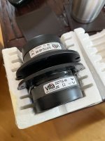
2. Pair of DNA-150 HF compression drivers. 1-3/8" T-18 thread screw-on mount, as for Eminence 10CX, etc. $35 for the pair, plus shipping (small and don't weigh much).

3. Pair of 1-3/8" screw mount to 2/3 bolt mount horn throat adapters. $15 plus shipping.

Prices are US dollars.

For Sale Tripath evaluation boards RB-TA3020;RB-TA0105

1680736686703.jpg
1728313674399.jpg


I have for sale the following evaluation boards from Tripath.
RB-TA3020-96€
RB-TA0105-160€
I do have more Tripath amplifier boards that you can check here:
https://www.ebay.de/usr/rocksandsound
Payment by Paypal tracked shipment,shipping to US on request.

For more information PM

Attachments

  • 1680736686707.jpg
    1680736686707.jpg
    469.9 KB · Views: 110
  • 1680736686697.jpg
    1680736686697.jpg
    467.8 KB · Views: 110
  • 1728313638310.jpg
    1728313638310.jpg
    465.1 KB · Views: 97
  • 1728313658505.jpg
    1728313658505.jpg
    447.7 KB · Views: 104

Stands for QUAD ESL-63 speakers

I recently rebuilt a pair of ESL-63s, and printed some 5 degree tilt back feet, but I don't like having the sound beamed up at my ears from close to the floor, so I designed and built some stands using 1"x1" and 1"x2" t-slot. The stands lift the speaker about 350 mm off the floor, and they are sturdy and center the weight so they aren't easy to knock over.

esl-63 on stand.jpg


Details and link to CAD file here. Extra bonus: they are high enough that my cat will probably stop using them as a scratching post.
  • Like
Reactions: Triodos

Cosmos APU a notch+LNA $70 to outperform APx555b for $30,000

Yeah, looks like a clickbait but I had such a design target.
Analog Processing Unit contains two devices in the same housing. THAT1510 based preamp-LNA 34/60db gain, 10Vrms max output level, and 48VDC phantom power, just in case if need to work with a condenser mic. The input impedance is 47kOhm 100pF in case it needs to use as a MM phono-preamp without RIAA(Cosmos ADC has internal DSP and may handle RIAA EQ online accurately). The input noise of the LNA is about 130nVrms(A) i.e.
5-6x times fewer than APx555 which, for instance, is not capable to measure the dynamic range of $13 Meizu HiFi DAC, APx555 result is 123-124db(A). Cirrus promises AES17 DR 130db(A) for CS43131, Cosmos APU+Cosmos ADC result is 130.5db(A) with 12db room to APU's residual AES17 DR for 2mV. The LNA's balanced inputs are clamped at 5-6V by TVS thru the 10ohm 0603 resistors in serial to each input i.e. an overvoltage with a good enough current rather may burn the resistors than TVS but that's safe for THAT1510.
The second and biggest half of Cosmos APU is the 1/10kHz active notch filter with -30db ratio(Q about 50) at the fundamental frequency and nearly 0db at 2nd and 3rd harmonics i.e. you can simply divide by 30(or subtract 30db) the THD/THD+N result to get a normal value. Also, with REW or Arta, you can use a calibration file to normalize the notch's frequency response and observe FFT results directly. The max balanced input level is 10Vrms, it is also clamped but by the active clamp with opamp's rail voltage-1V, hence, 10ohm 0603 again may be burned like a fuse. The residual harmonics of the distortions are <-150db@1kHz or <-130db@10kHz, that's probably isn't too spectacular but still better than APx555. The residual THD+N, practically achieved one, -132db@1kHz@10Vrms(DAC+LPF approach), calculations based one is -134db but I can't confirm that so far because of can't find a perfect-zero-noise sine for that 😉 It is clear that APU is kinda a microscope for your ADC, even any laptop audio input with APU gets the ability to measure a tiny noise of DACs or LDOs, and distortion levels are perhaps lower than AP SYS2722 or even Cosmos ADC.
The best way to power Cosmos APU with a power-bank(or a good smartphone charger), is to minimize GND loops issues.
The device is quite simple and inexpensive, strange that's not on the market already. Especially inexpensive(~$70) would be a version without the case as a PCBA which any DIYer can adjust by 4pcs trim-pots(2pcs for the 1kHz Twin-T -30db or -40db, another pair for 10kHz -30db).


REW with the calibration file DAC+LPF->CosmosAPU->CosmosADC
DAC+LPF_APU_Cosmos_ADC.jpg


The residual THD+N of 5 preproduction samples, -101db of reading need to subtract 30db i.e. THD+N -131db@9.5Vrms the same about harmonics -127db means -157db
S1_THD+N_9.5V.jpg


S2_THD+N_9.5V.jpg

S3_THD+N_9.5V.jpg

S4_THD+N_9.5V.jpg


APU Notch frequency responses:
APU_Notch_10kHz.PNG


APU_Notch_1kHz.PNG


AES17 Dynamic Range test performs at -60dbfs level by measuring the THD+N A-weighted. That plot shows the residual THD+N (A) of the LNA at 1-10mV level sweep. 2mV corresponds 2V 0dbfs DAC like CS43131, and -82db needs to subtract 60db to get AES17 DR = 142db. A typical high-performance DAC with 5Vrms 0dbfs could be measured down to 150db and so on.

APU_AES17DR.PNG


The residual noise of 5 preproduction samples(the S2 using SSM2019 instead of THAT1510), the reading need to divide by 1000 due to 60db of LNA i.e. a uV is actually nV.

APU_NOISE_60db.PNG


The gain of Cosmos APU preamp is +60db(1000x times), hence the scale units are nVrms(A). After the APU unit turns On, you can see 5s of settling,
from 6s the input noise reaches 130nV, about 9s 48V power was turned On, and after 1s reached 142nS. Hence, APU's phantom power adds just 12nV to the preamp noise, that's a nearly ideal result as I think 😉 The test was performed with a shorted preamp's inputs(In+ to In-) and biased to the GND by 2x6.8kOhm resistor as a dummy condenser mic.
LNA_48V_noise.PNG


and the spectrum 20Hz-130kHz of the same test, units need to divide by 1000 as well, so uV becomes nV. This is a good illustration to killing the myth that SMPS is always dirty 😉 Cosmos APU contains no linear voltage regulators at all, only SMPS with Fswitching > 1MHz.
LNA_48V_noise_FFT.PNG


Finally, I got working Cosmos ADC with internal DSP and RIAA EQ implemented for all Fs from 44.1 to 384. A pair of Cosmos APU was used as a dual-mono phono preamp +34db gain with no analog RIAA, which was applied in Cosmos ADC digitally. The video is a comparison of LP vs CD sound, recorded this way.
The formal specs of such a combo:
THD+N@5mV-40ohm(AP output) -83db, and suddenly it places Cosmos APU to the 2nd position of the phono-preamps ASR rating(and yes, I know his tests are silly) 😉
APU+ADC_RIAA_5mV.jpg


I remeasured Cosmos APU+Cosmos ADC+RIAA max accurate, AC line hum virtually zero.
5mV 10ohm source APU gain 34db Cosmos ADC 1.7V sensitivity, THD+N -89db or -97.7db(A). Due to H2 and H3 being very low, SNR is also 97db(A).
2022-05-31_23-12-09.jpg


250uV 10ohm source APU gain 60db Cosmos ADC 1.7V sensitivity, THD+N -66db or -78db(A). Due to H2 and H3 being lower than the noise floor, SNR is also 78db(A).
2022-05-31_23-06-43.jpg


The real SNR i.e. APU source is a cheap MM cartridge AT3600L, the LP record is digitized by Cosmos ADC@32/384, normalized to fit max peak to the -6dbfs, next, the stylus is up to the air, Pioneer PL-300(made in Japan 1980) turntable keeps 33.33rpm. This way the SNR = 91,2dbfs-6db=85.2db(A), that's looks decent if the LP "silence" between the tracks shows SNR = 65db(A) and less.
APU+ADC_RIAA_AT3600L_SNR.jpg


Of course, both these functions, mic and phono preamp, are features just for the feature list, but I think both are decently implemented and virtually for free so I couldn't call that a marketing 😉

https://e1dashz.wixsite.com/index/cosmos-apu
https://archimago.blogspot.com/2022/05/early-look-cosmos-apu-high-performance.html#more
https://www.l7audiolab.com/f/e1da-cosmos-apu-2/ APx555b measurements
Login to view embedded media

Attachments

  • 2022-04-25_13-09-50.jpg
    2022-04-25_13-09-50.jpg
    462.4 KB · Views: 561
  • 2022-04-22_23-41-56.jpg
    2022-04-22_23-41-56.jpg
    335.4 KB · Views: 598
  • APU_Notch_10kHz.PNG
    APU_Notch_10kHz.PNG
    17 KB · Views: 806

Rega Elicit Mk2 volume control issue

Hi there. I have enjoyed a fine Rega Elicit mk2 amplifier for several years. However, recently I noticed that at a certain position of the volume control (or rather the LED track, as the knob has no fixed position) the sound from the left channel disappears, if I turn the control knob (or remote control) a few clicks clockwise the sound reappears, although it is slightly muffled. I checked different inputs, different sound sources - the problem does not disappear, the sound from the left channel disappears exactly in this position of the LEDs. I need your help.

Large Electrolytic Capacitors FS (new)

I have twelve (12) brand new 22,000 uF, 80V capacitors. Ordering error from Mouser and I'm stuck with them. I'm trying to recover some funds. Asking $35 each, plus USPS shipping from zip 17402.

4.125 inches tall and 2.5 inches in diameter. Great for all your power amp projects! Send me a PM if you're interested.

Mouser part number: 598-CGS223U080W4C
1000012279.jpg
  • Like
Reactions: HumbleDeer

Tweeter off-axis patterns

Background – I’ve built speakers in the past but my most recent build was in 1999. So I am trying to read and catch up with current speaker building trends.

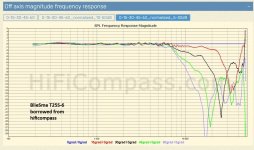
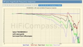
A lot more attention is being paid to off-axis performance these days. I gather that consistent and as wide as possible directivity are said to give a more realistic sound. That said, I am seeing two different approaches to off axis in tweeters. I have borrowed a couple of normalized off-axis curves from hificompass.com to demonstrate. Many thanks to them for their fine measurements.

Some folks are trying to keep the widest directivity to as high a frequency as possible followed by a smooth narrowing at higher frequencies. An example of this is the BlieSma T25S-6 where there is no narrowing of the off-axis curves until about 6.5k Hz. Then it narrows linearly until a break-up in the 17k – 20k region.

Others prefer an early but smooth narrowing, often accomplished with a wave guide. An example of this philosophy is the Satori TW29BNWG-4 which uses a wave guide and starts narrowing about 1300 Hz. As it happens, hificompass.com offers 3D printer plans for a the BlieSma T25S-6 which changes the T25S-6 into something like the Satori.

My question is which kind of directivity pattern is preferred and why? If it’s just preference, what are the advantages and disadvantages of each.

BlieSma T25s-6.jpgsatori tw29bnwg-4.jpg
Thanks.

Simple DC step down solution

I'm adapting an existing ps to supply +/- 15-20 vdc to preamp boards that draw zbout 55ma per rail. I'm planning to use an existing transformer and have a simple PSU board to adapt with spare parts to provide the vdc to the boards I've built. Once the AC from the transformer (23-0-23vac) has been converted to VDC via a bridge rectifier it then has some bulk caps. The output voltage is, however, 31.8vdc (unloaded) and I'm looking for a simple way of reducing this to 15-20vdc bearing in mind the 55ma draw of each board. What would you good folk recommend to achieve this? I have a simple option on the existing board to insert a through hole component... The boards have regulators so I just need stable raw power supply that can handle the current draw without smoking...

A guide to building the Pass F4 amplifier

Building the Pass/Firstwatt F4

This is a fantastically good sounding amp - read more about it here before staring;

https://www.firstwatt.com/wp-content/uploads/2023/08/prod_f4_man.pdf

The thread at DIY audio -

http://www.diyaudio.com/forums/pass-labs/97540-f4-power-amplifier.html

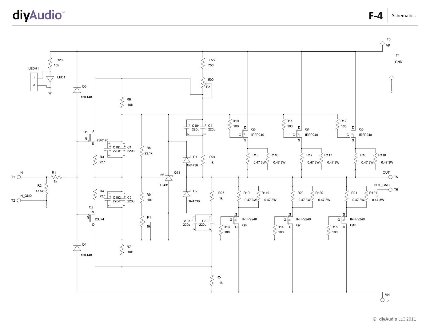
And this the the corrected schematic (The schematic in the Firstwatt article has a typo, also this one agrees with the PCB)

P-F4-1V20-schematic_zps32c28b0a.jpg


Here you will find a build guide for the Pass / Firstwatt F4 power amplifier using PCBs and chassis from the DIYaudio store.

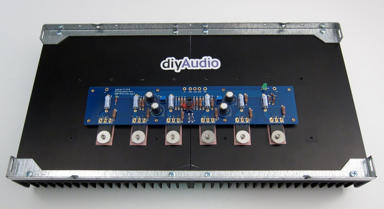
The 5U 'BIG Amp Chassis' is shown, because that's the one I have. It will fit comfortably in a 4U 'Jack of all chassis' and have enough heatsink as well.

~~~~~

There are plenty of places that you could start, but for the sake of illustration let's begin with the heatsink assemblies -

IMG_1391_zps4ef8a39d.jpg


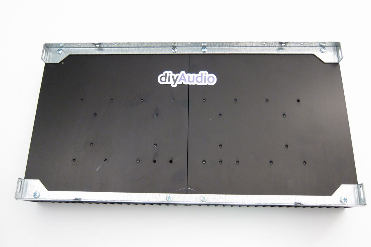
This is the heatsink(s) from the 5U 'BIG Amp Chassis' It has a mirror-imaged set of pre-drilled heatsinks and brackets to hole them together and make a mounting point for the rest of the enclosure. The 4U is similar, but the heatsink is a single piece.


IMG_1366_zps82f8a4cd.jpg

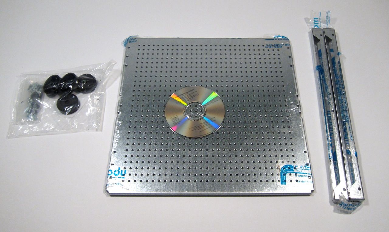
This build will also utilize the 'DIY friendly' baseplate, here shown with the feet and hardware, and also the heatsink's brackets.

An externally hosted image should be here but it was not working when we last tested it.

There is a hardware package available for the pre-drilled back and heatsinks, including input and output jacks, IEC module, and hardware for the PCB and heatsinks.

IMG_1352_zps9fb0c96c.jpg

The contents of the hardware bag.

IMG_1393_zps85a2e08a.jpeg

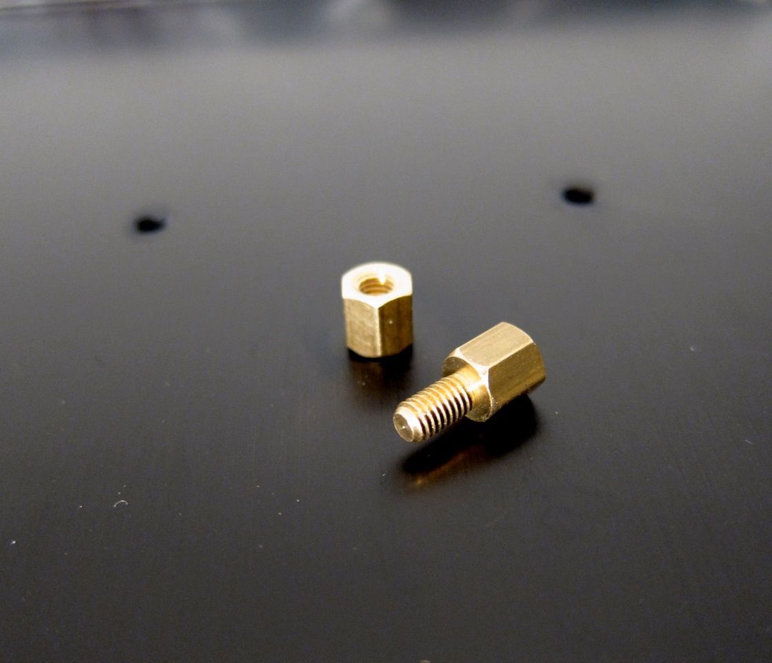
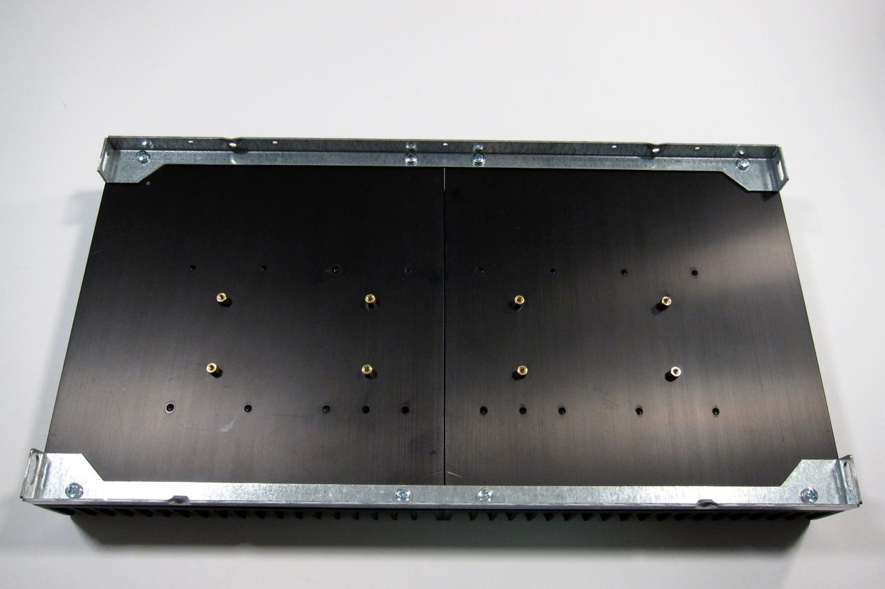
Using the brass PCB standoffs, install them into the PCB mount holes as shown, to get the following pattern;

IMG_1394_zpsf97a8602.jpg

Now there is a place to mount the amplifier PCB

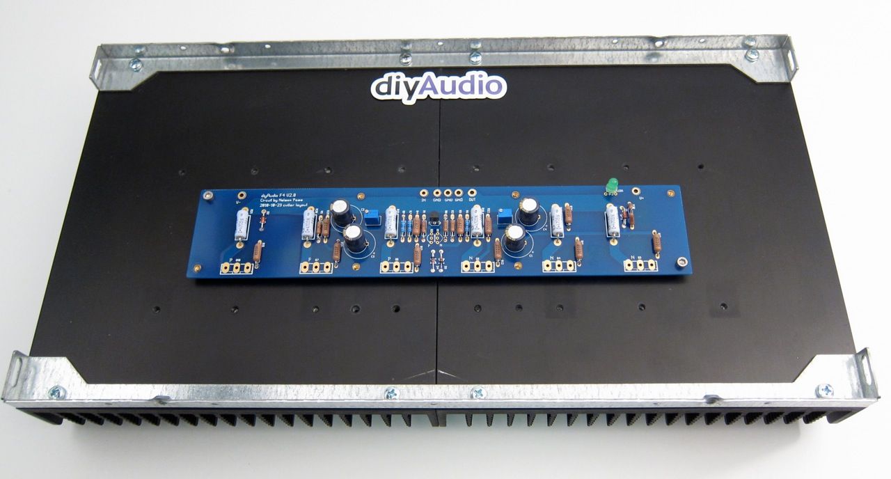
IMG_1328_zps1544a1a0.jpg

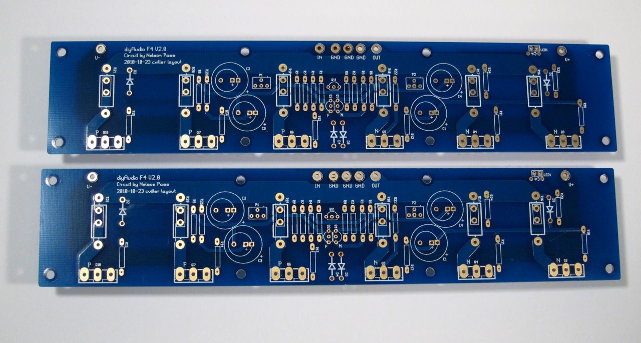
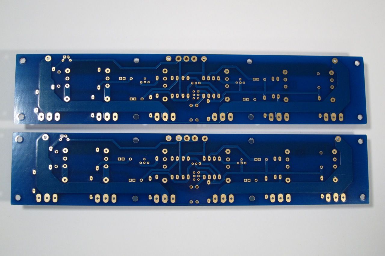
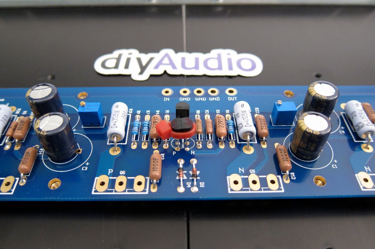
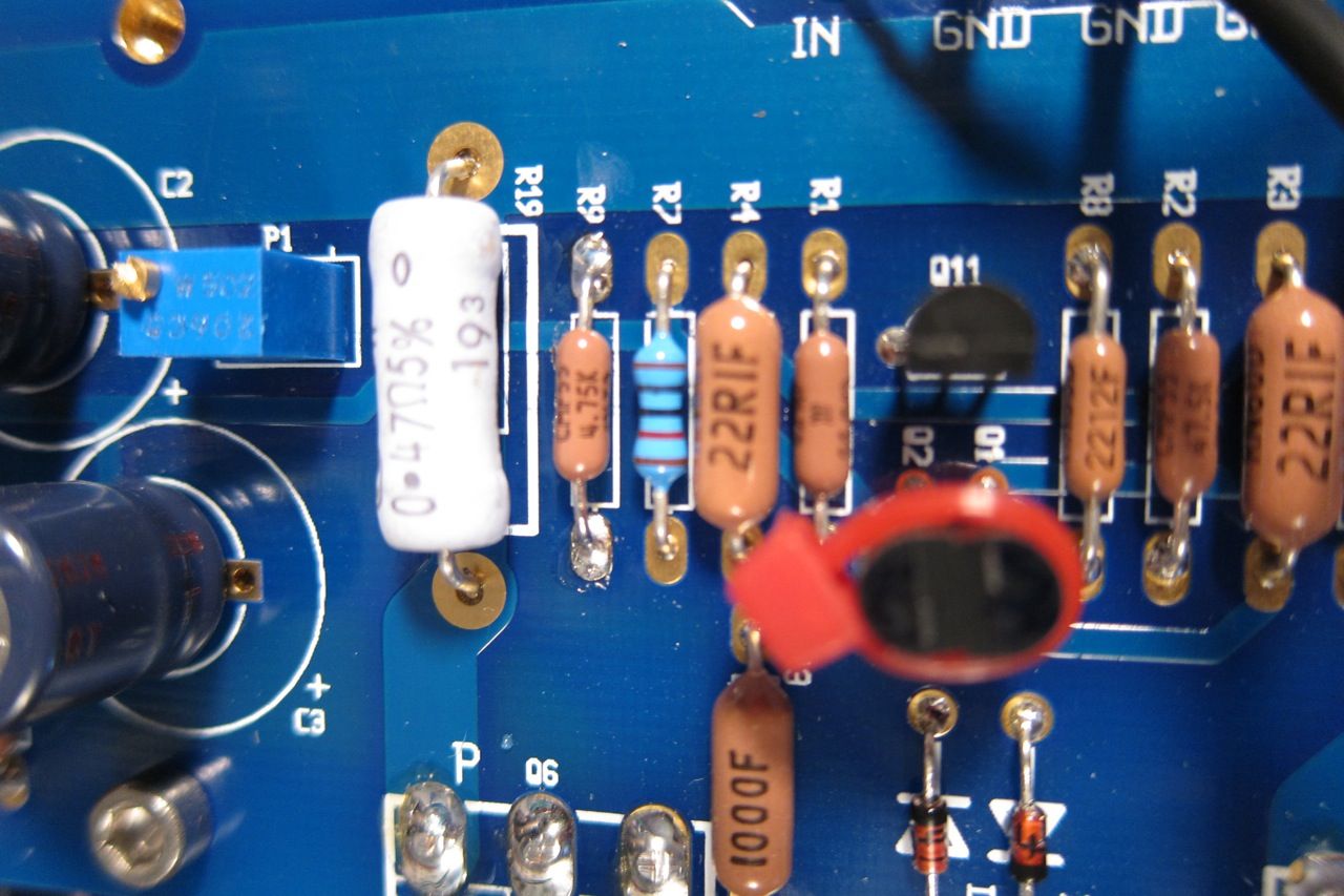
Speaking of PCB, it's a very nice layout, plenty of room, and the ability to use many sizes of resistors and caps. This is the front.

F4PCBback_zps5890d195.jpg

Here is the back.

IMG_1474_zps77bafab7.jpg

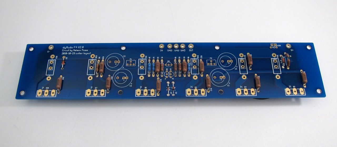
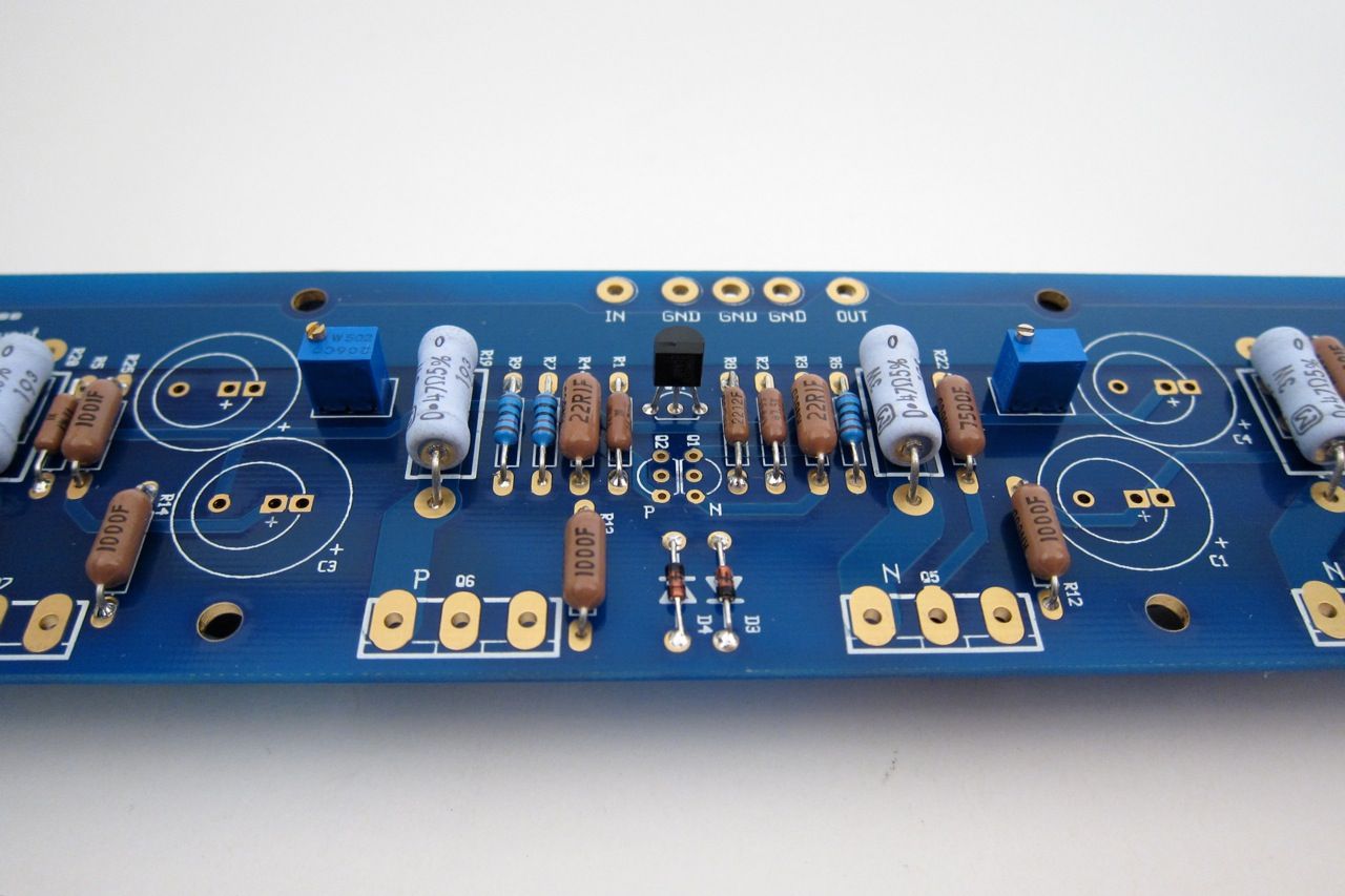
Stuffing the PCB should be done in the usual order, from smallest device to biggest - so that would be diodes and resistors first.

Of note, I got the bigger (Dale/Vishay RN60) resistors to see how they would fit on the PCB. They are the size of the PRP resistors that are quite popular amongst the fancy parts crowd. They are great everywhere except the row flanking the small transistors right in the middle. They don't fit there side by side. You could mount them soldier style, or just mix in a few smaller resistors like I did. Or just get RN55's. They are the smaller size.

IMG_1477_zps30cf4d2c.jpg

Pots and transistors next. (yes, I didn't stuff the input pair when the photo was taken…)

IMG_1489_zps65e7fd6f.jpg

Ah, there they are.
The ziptie is just to help their thermal tracking.

IMG_1480_zpsf8e420df.jpg

And finally the capacitors.

IMG_1486_zps795ceade.jpg

There is a top and bottom to the Universal Mounting Spec holes, the board mounts as shown

IMG_1494_zps3359f3f7.jpg

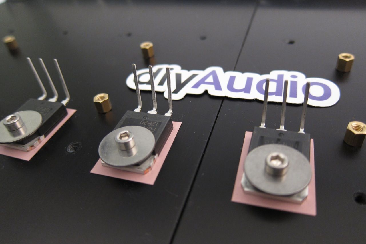
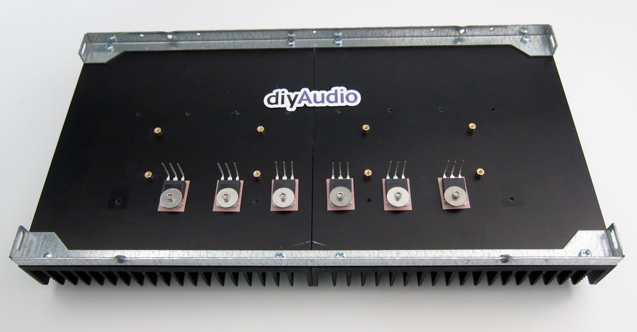
I find it helpful to bend the leads of the transistors first, and mount them (a little bit loose) to the heatsink.

IMG_1492_zpsdec762b0.jpg

Like this

IMG_1490_zps1192f349.jpg

And then mount the PCB. You can snug all the screws down and then solder and trim.

Ok, now lets move on to the Power Supply.

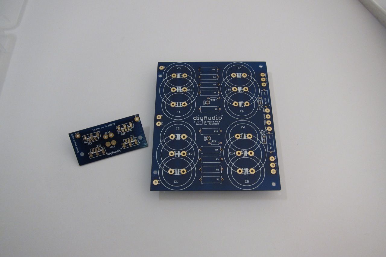
PSUboard_zps616b983c.jpg

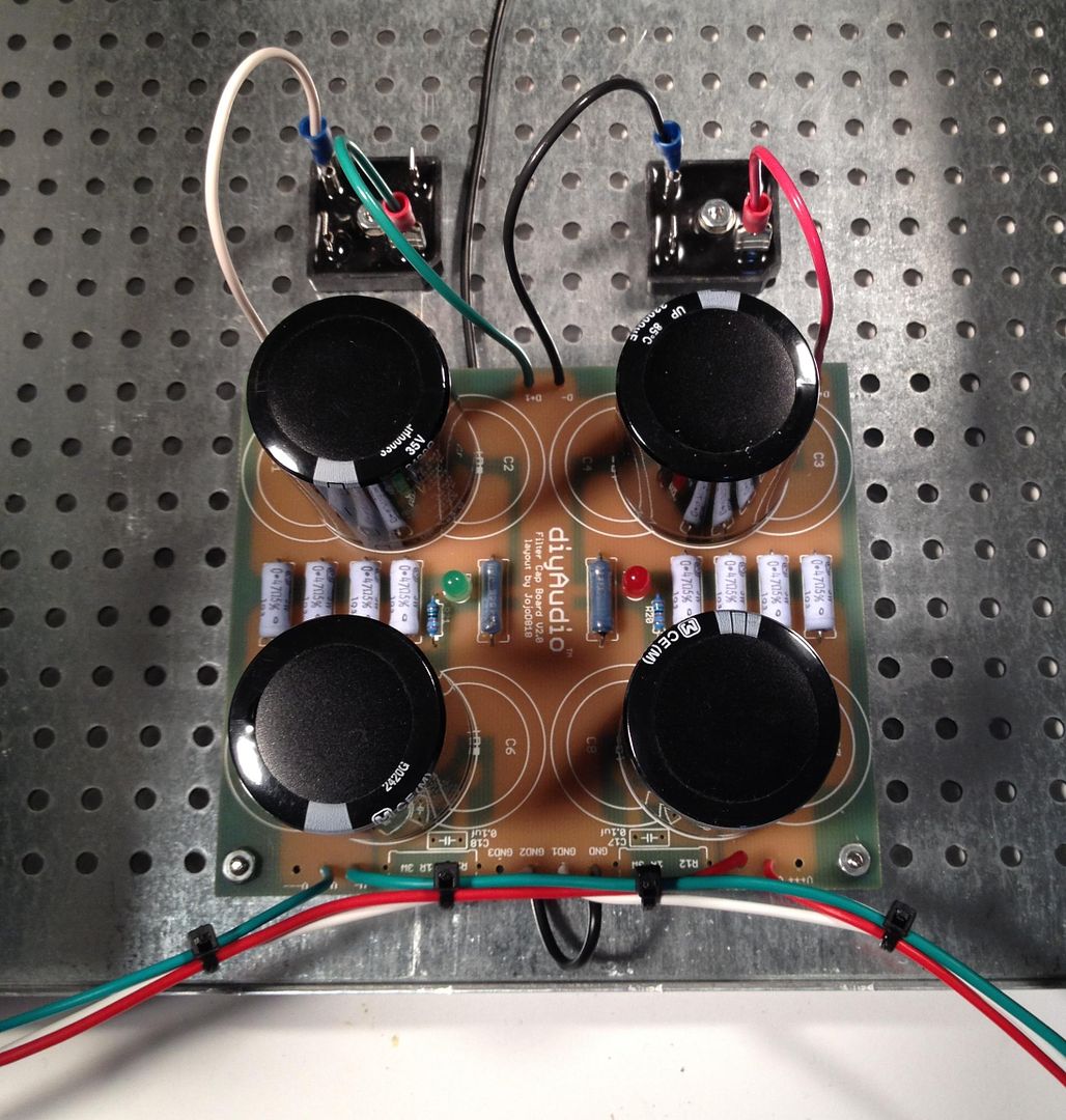
Here is a photo of the PSU board, I am going to use integrated bridge rectifier blocks, so you need to remove the part of the PCB that mounts the diodes. The new PCB, not quite yet available at the time of this writing, will have a similar feature with the diodes, as well as room for more/bigger capacitors.

9c96c03e-67e2-4c92-8538-8d219c9ab64e_zps30c7bdad.jpg

As always, stuff the small components first - the light blue resistors are the filter resistors, the darker ones with the teflon are the bleeder resistors, and the small ones are for the LEDs.

This PSU board is the exact same DIYaudio PSU board, just without the top blue soldermask.

PSUfull_zpsd50e6012.jpg

This shows the INPUT edge (from the diode bridges)

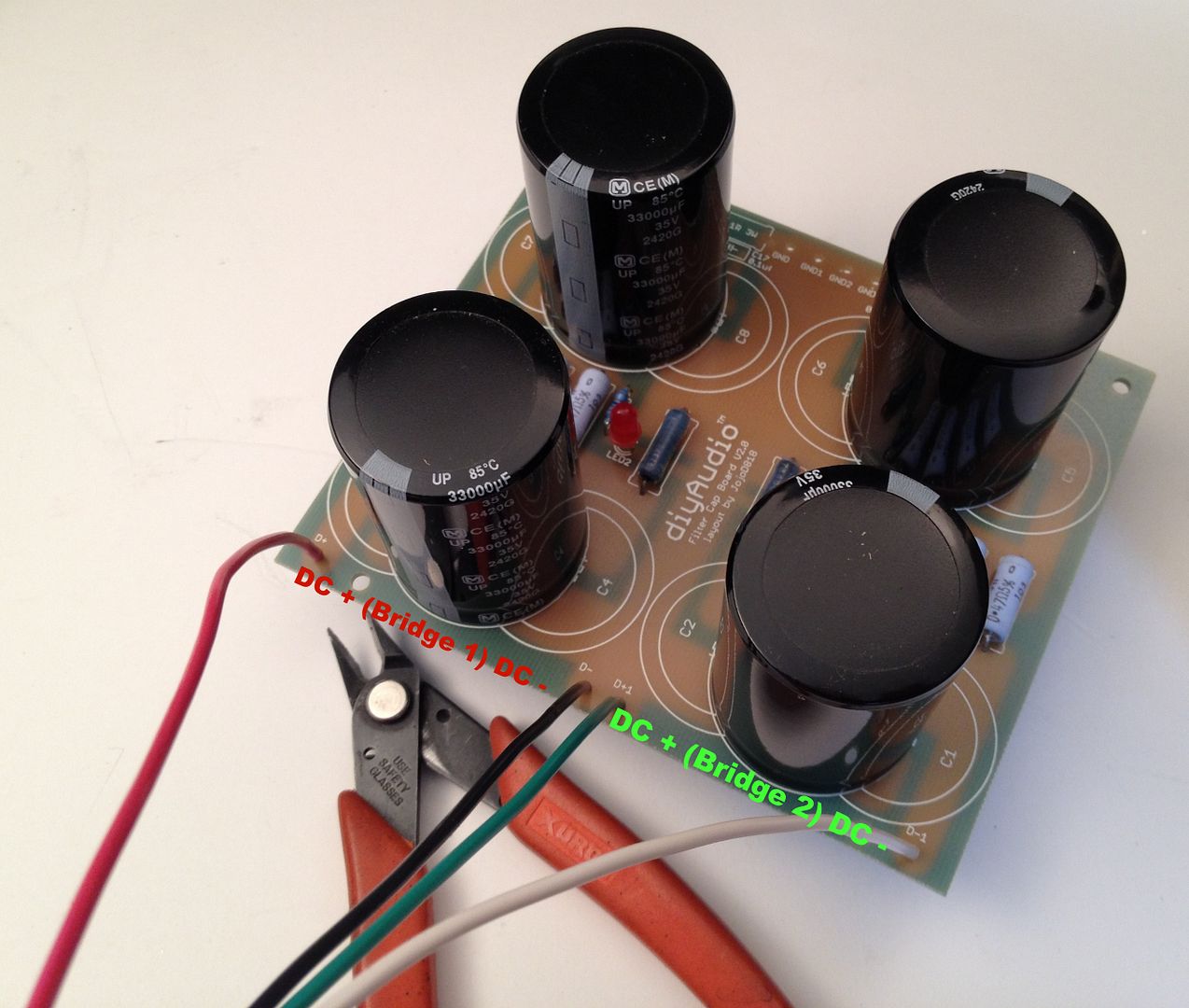
The capacitors are Panasonic T-UP 33,000uf 35V

bridges_zpsbec07865.jpg

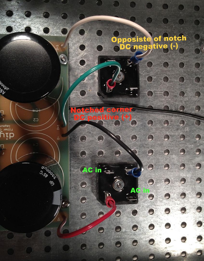
Connecting the bridges to the PCB

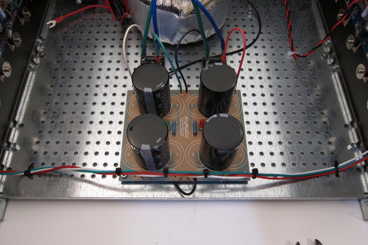
PSUonChassis_zpsf0ac7805.jpg


b2a3196d-cd27-413e-91d8-416854498ff7_zps6e21e4c3.jpg

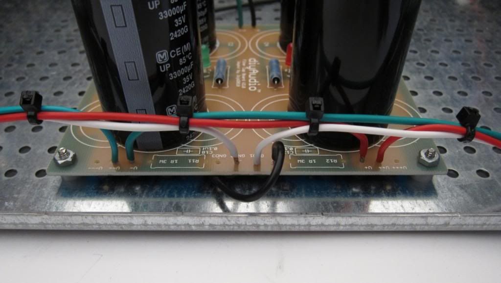
This is the OUTPUT edge of the PSU - the colors are
Red V+
White GND
Green V-
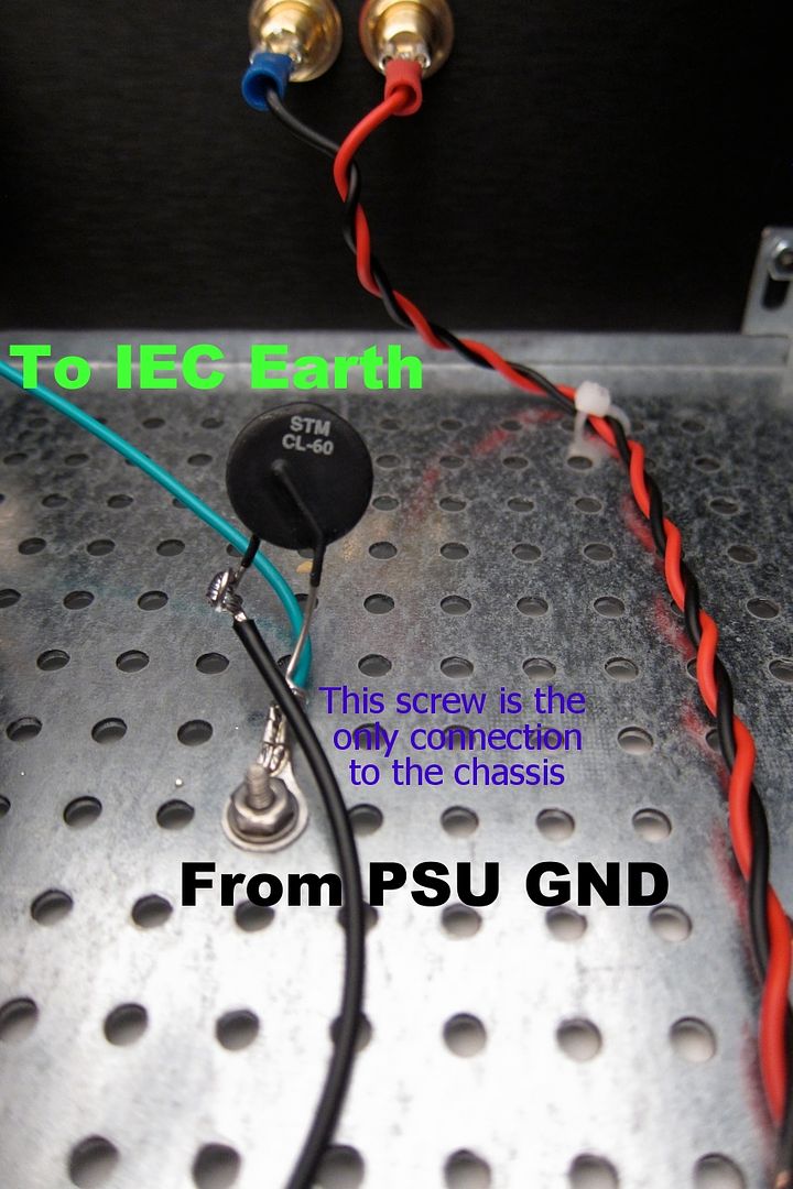
The black connects the PSU GND to the CL-60 to the chassis.

IMG_1496_zpsd0648203.jpg

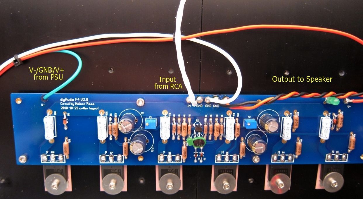
The wiring from the PSU to the amp PCB is clearly shown.

IMG_1502_zps595e76c4.jpg

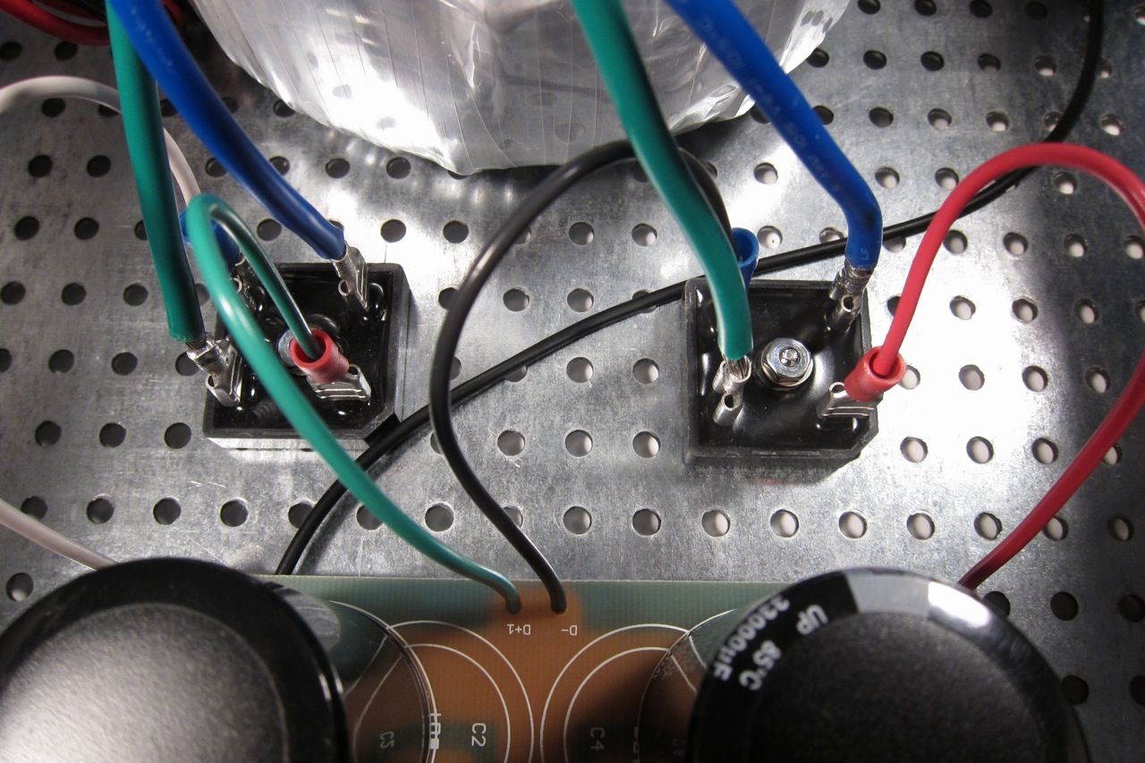
Here you can see the bridges with the wires attached from the transformer secondary. Remember that the green attached to a bridge must have continuity with the blue attached to the same bridge. (As it's the 2 ends of the same piece of wire)


IMG_1504_zps2330b348.jpg

As long as were are tailing about the transformer, here is a photo of the terminal block shown wired for 120v. The Blur lead is the AC Live, and the clear the AC neutral. The reds and blacks are the transformer primaries.

Transformer is an Antek 400VA 18v+18v, part number AN-4218.

c18876a2-f60a-4a7c-88c1-df7c2333efdb_zps3ff1ace7.jpg


The last bit of the PSU wiring is the chassis connection, the black comes from the PSU GND, and the green is the AC safety earth.

The AC to primary wiring confuses everybody, so;

Let's look at the PSU schematic just to make sure everything is OK... Remember that I am wiring it for 120v operation, so the transformer primaries are in parallel. People wiring for 240 with a transformer like this, please ignore.

F5PSUschematic.jpg


Notes in red are mine.

Look at the connections of the transformer primary, through the thermistors and line cap, to the mains.

Hot AC is connected to the "120" (which in my case is the red leads on the primaries) One red primary is connected to AC hot through a thermistor.

Neutral AC is connected to the black "0" leads, one of which is connected to the AC through a thermistor.

AC Hot and Neutral have a cap across the leads.


So, yes, the AC will be connected to the center 2 posts, which is across the cap.

DSCF0098.jpg

(This photo lifted from my F5 thread, but it's the same PSU…)

Left to right we have post 1, 2, 3, 4

POST 1 - Transformer primary 'B 0' which will be connected to AC Neutral at post 2, through the thermistor between post 1 and 2.

POST 2 - AC Neutral in (not shown in photo), connected to Transformer primary 'A 0" , a thermistor to post 1, and a line cap to post 3

POST 3 - AC Hot in, connected to transformer primary "B 120", thermistor to post 4, and line cap to post 2

POST 4 - Transformer primary "A 120", connected to AC Hot through the thermistor to post 3

If you look at the red and black wires in the photo you will see that the Mains AC must to pass through a thermistor to connect to each of the 2 primaries. And that is the point of them, to keep inrush under control during powerup.

Ok!

Now we need to put everything together -

But first a bit more mechanical assembly.

IMG_1318_zps154c4eb4.jpg

This is the pre-cut back plate and the thick front plate.

IMG_1373_zps4feae671.jpg

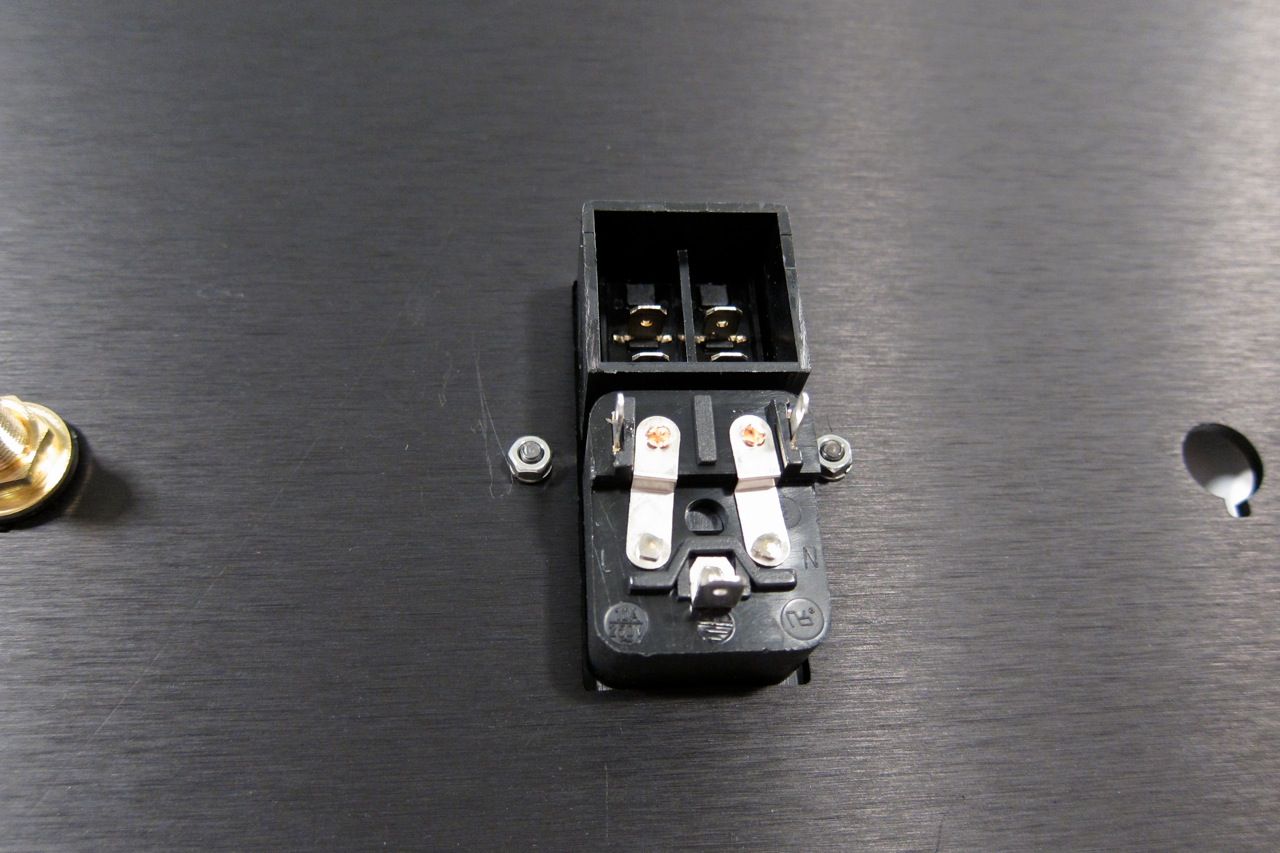
Gather and mount the IEC plug.

IMG_1374_zpsea052fad.jpg


IMG_1375_zpsf81194a0.jpg

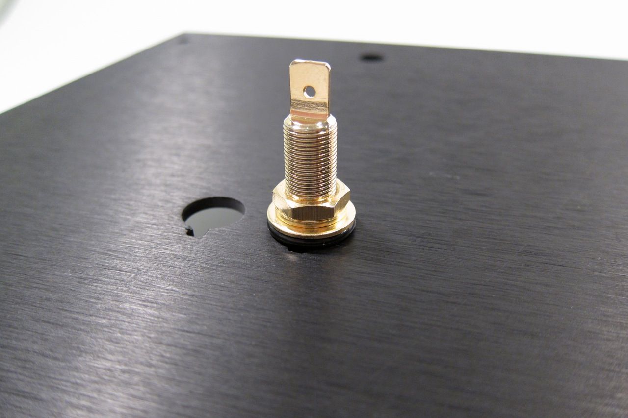
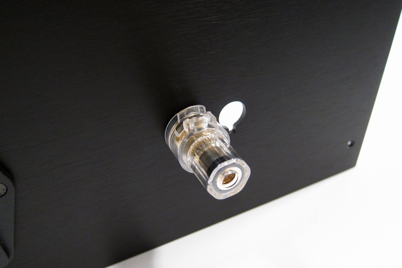
The speaker posts.

IMG_1376_zps78619adc.jpg


IMG_1377_zps52d02da2.jpeg

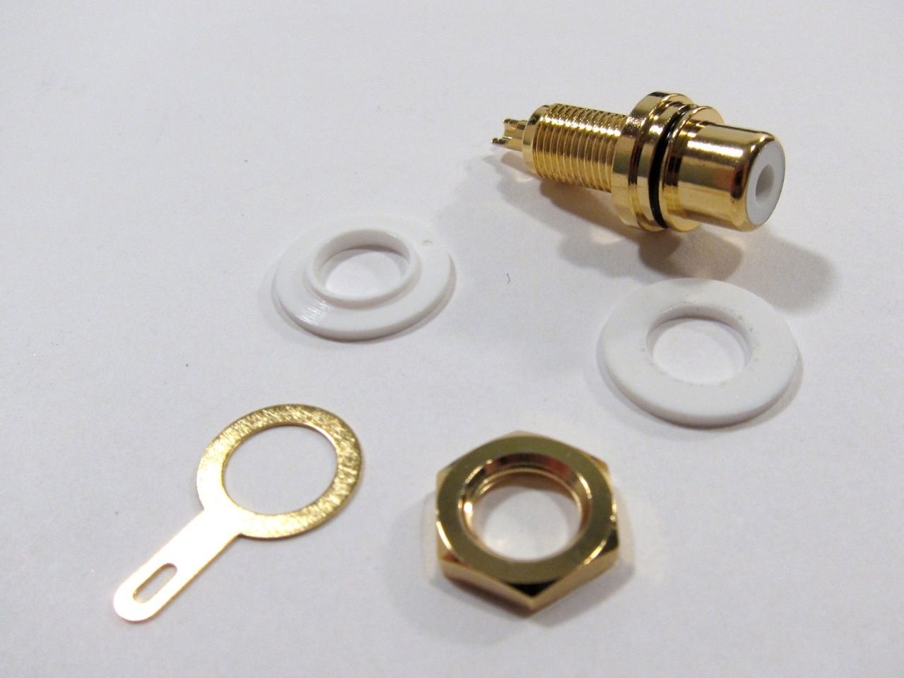
And the RCA jacks.

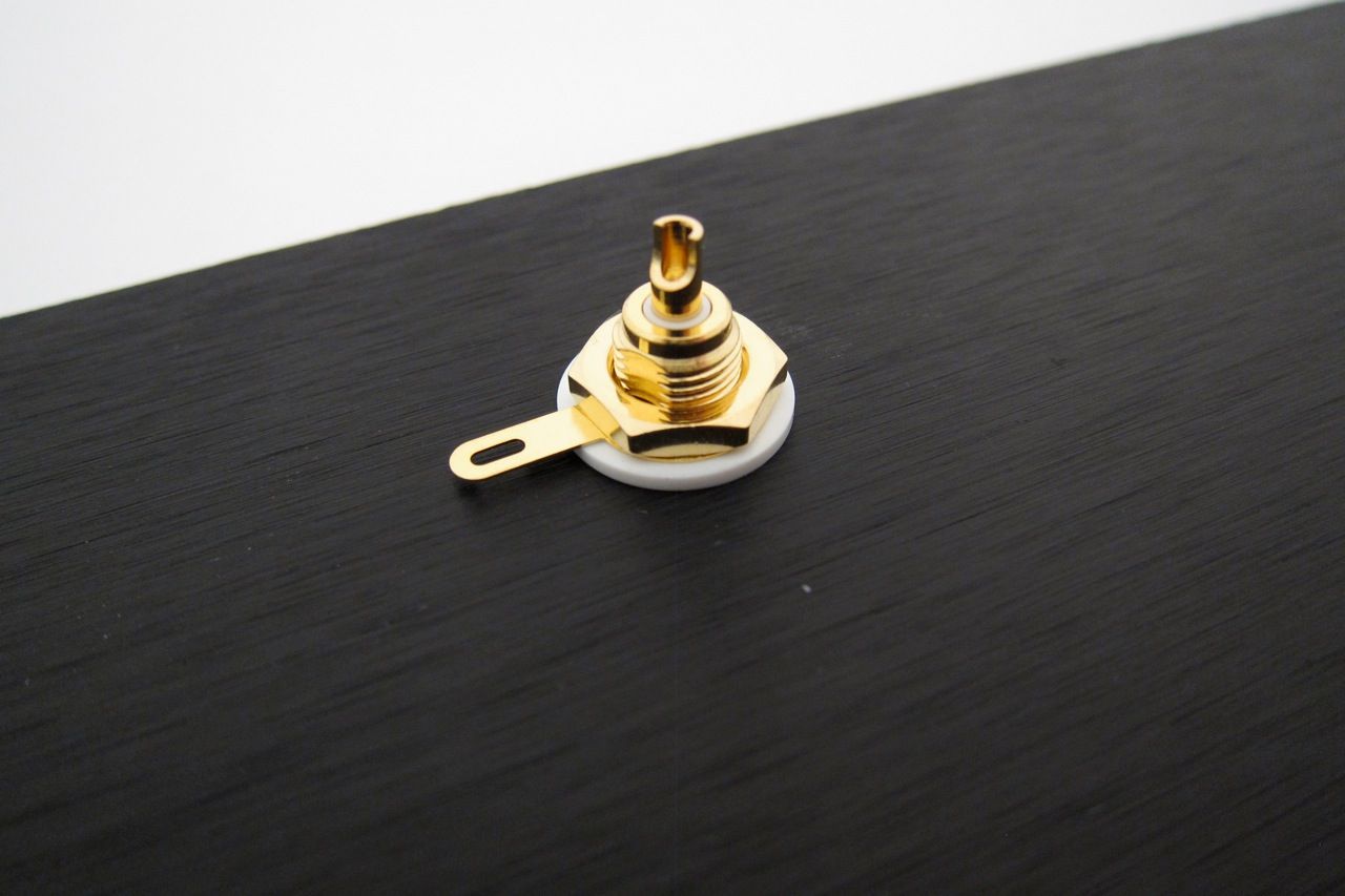
Note that the shoulder washer goes on the inside, so the metal of the chassis doesn't touch the metal of the jack. There is a similar washer on the speaker posts.

IMG_1379_zps7ea37734.jpg


IMG_1383_zps81466a6f.jpg

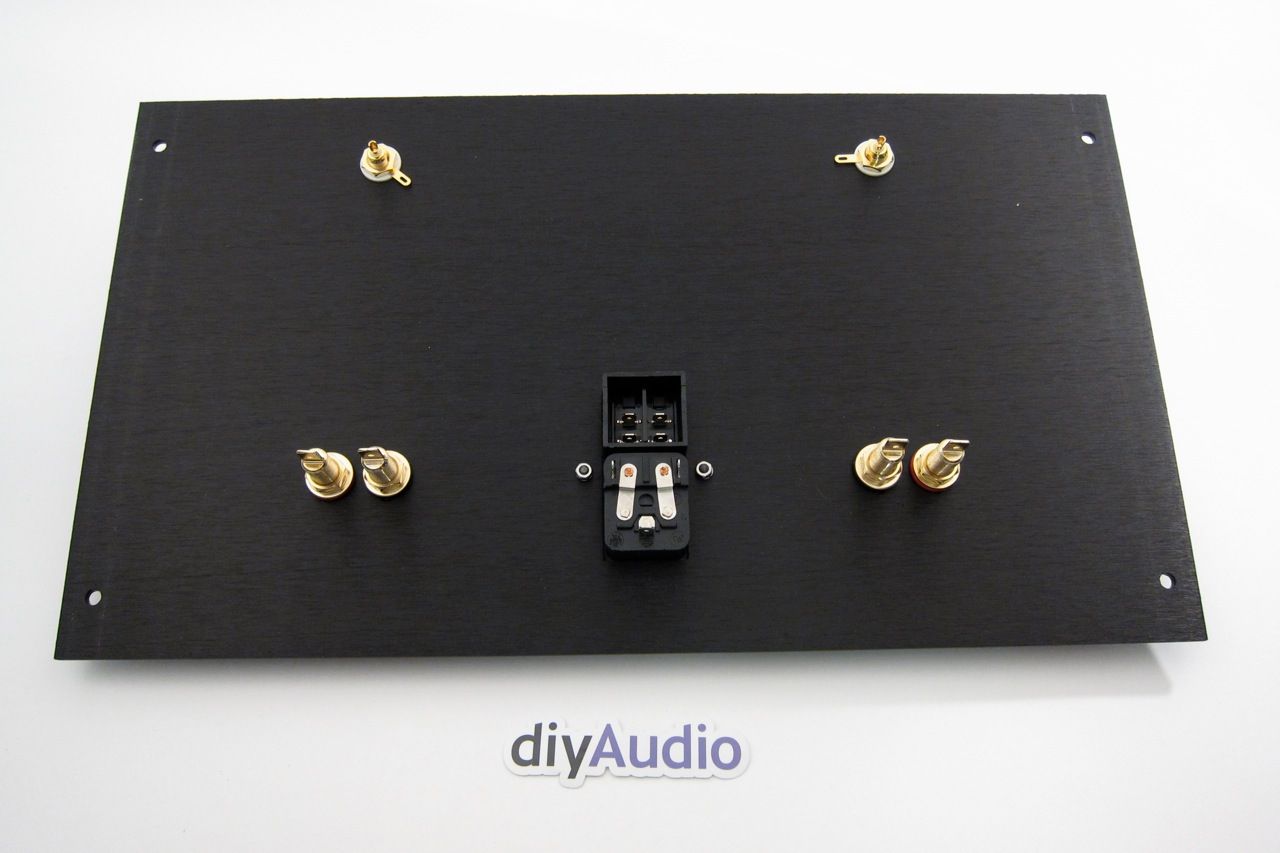
The inside of the back panel.

IMG_1384_zpsa6eac495.jpg

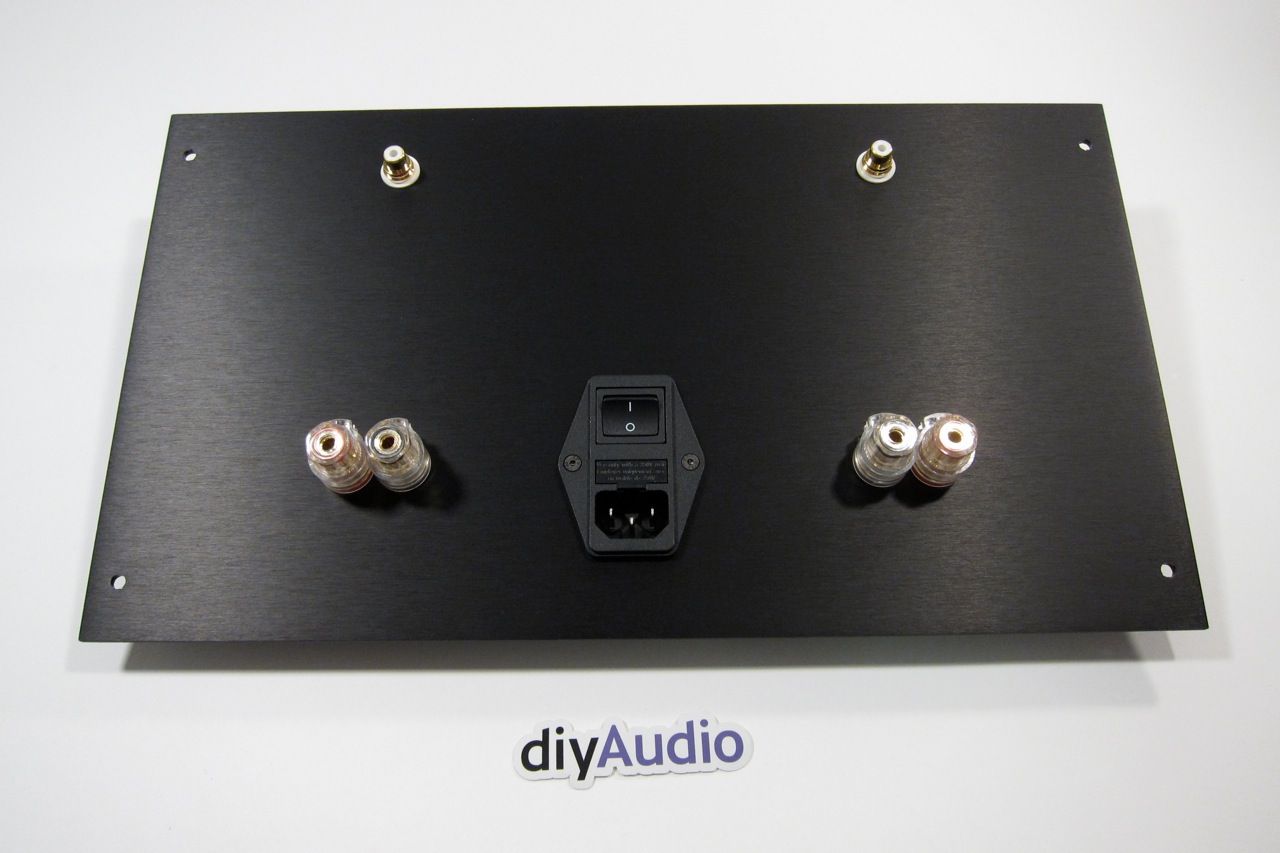
And the outside. Looks good, yes?

F4IEC_zps6ceffebf.jpg

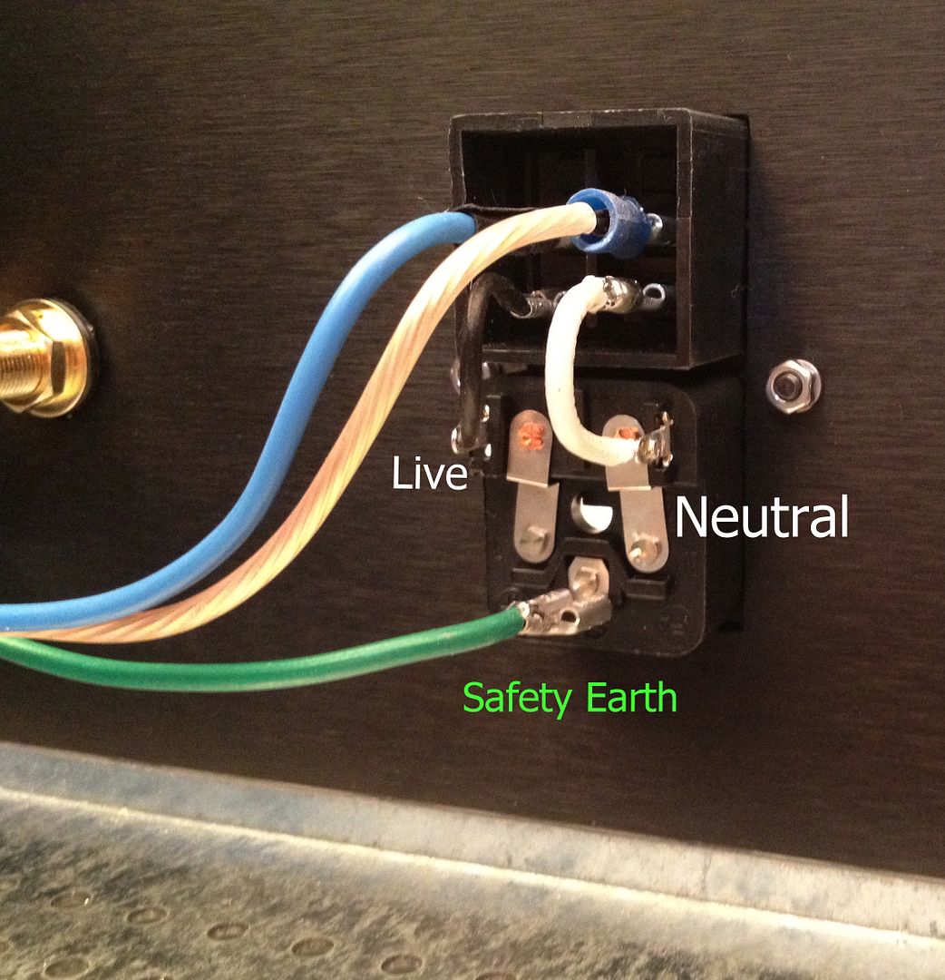
The IEC module is wired as shown. This will switch both the Live and Neutral. The blue (live) and clear (neutral) go the the wiring block with the thermistors, cap and transformer primaries.

F4_zps1c20d402.jpg

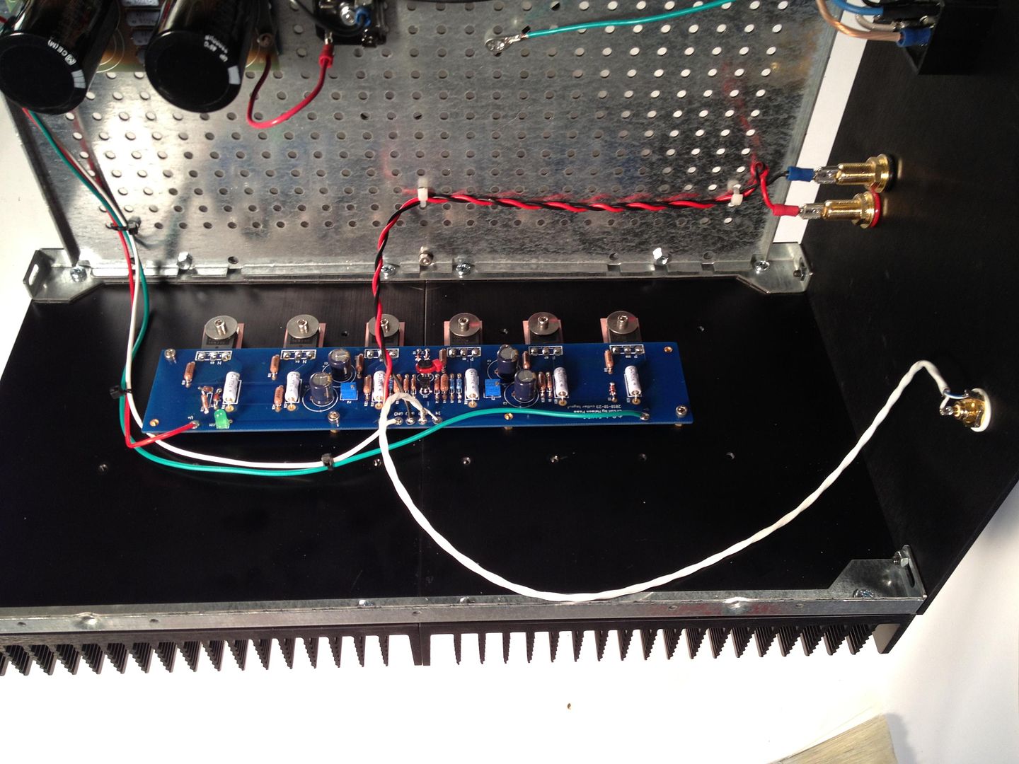
The amp PCB completely wired.

IMG_1500_zpse2fd0def.jpg

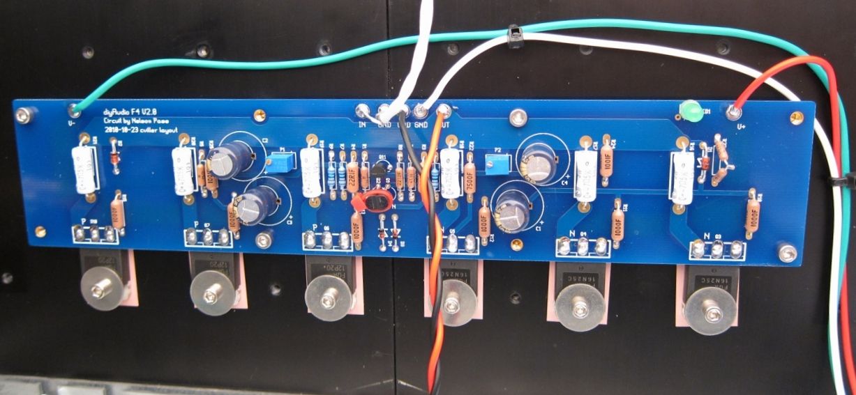
A bit closer.

IMG_1508_zps204b9870.jpg

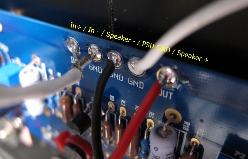
The top connections labeled.

IMG_1501_zps9fc1ace7.jpg

This happens to be the other channel, but the connections are all the same.

Remember that V- / GND / V+ is always left to right as you are looking at the format of the PCB

IMG_1509_zpsf813f64d.jpg

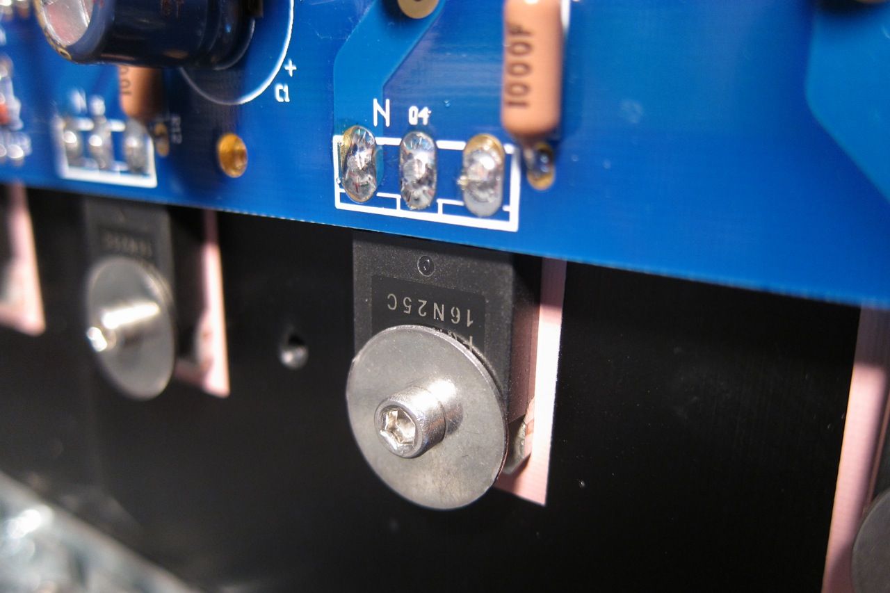
I'm not entirely sure what I was trying to show here, other than the screw and washer. It looks cool. I will keep the photo in the guide.

IMG_1507_zps4cbad30f.jpg


IMG_1515_zps250cb1fc.jpg

A few notes on bias -
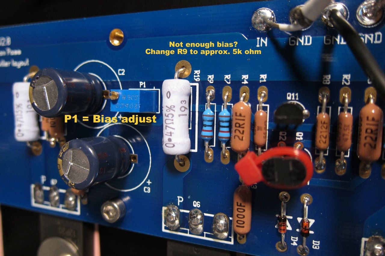
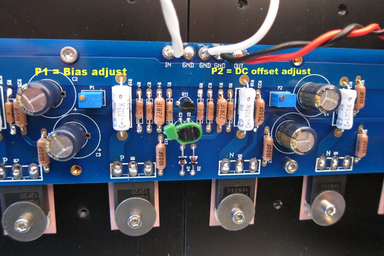
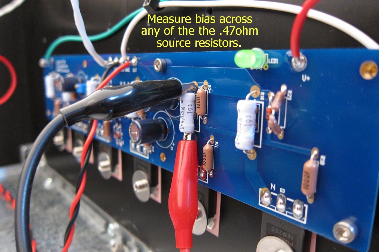
P1 controls the bias, measured across any of the 3W source resistors. Adjust for 0.13v when it's cold, and watch that it doesn't get higher than 0.2v once it's up to temperature in about an hour. Adjust for 0.2v when hot.

P2 is used to adjust the DC offset on the output to zero.

IMG_1517_zpsb9663755.jpg

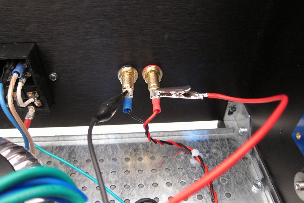
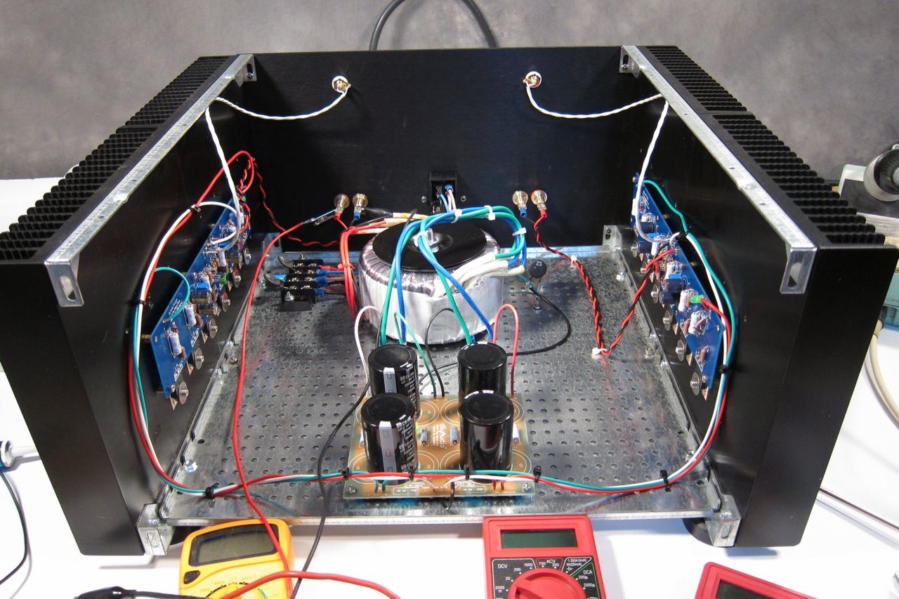
Attach a DC voltmeter across the speaker outputs to measure offset.


IMG_1512_zps4b4f9e14.jpg

If you find that the P1 doesn't have enough range, I.E., you can't turn it up enough, replace R9 with a smaller resistor, I used 4.75K and it works well.


IMG_1513_zps62a0e474.jpg

Connect a voltmeter across any of the source resistors. The outboard ones are easier to clip across.

Adjust for about 0.13v cold, and once the amp is up to operating temperature, trim for 0.20v - It takes a long time to warm up, take your time.

Adjust P2 for zero offset, then re-trim P1

Here is a photo of it all connected and working -

IMG_1506_zpsbb6eed41.jpg


I'm driving the F4 with an O2 Headphone amp sourced from an iPod; Driving 85.5db speakers. Although it is a small room, it gets louder than I want to listen. It still can't drive it to clipping, but it does get really, really loud.

One thing worth mentioning, and it speaks very highly to the quality of the amp, is that it is completely non-fatiguing, and more interestingly, very easy to listen to turned up too loud… I don't realize how loud it actually is sometimes. Complete transparency is a word used a lot when describing this amp - but I have to agree. It's fantastic!


Please comment away if you desire.

Also please feel free to ask any F4 questions here, and if you would like to post photos of your F4 completions, old or new, please do!

C.E.C AMP3300R (3300 R Amp 3300R Amp3300) and AMP5300R LEF Class A schematic wanted

CEC (C.E.C) claim by their mostly amplifier models, it's class A (here in Germany even "Pure Class A") The name of circuit topology is "LEF (Load Effect Free). The developer is Mr. Carlos Candeias. Have a look to this URLs: Amp 3300R:
CEC AMP3300R
and Amp 5300R (Amp5300R Amp 5300R Amp5300)
CEC EUROPE WEBSITE
The last model delivers 120W/8 ohms and 135W/4 ohms, as to read in the CEC datasheet
If anybody can posted the schematic of one of both models, I will make an evaluation. I guess, the term "Pure Class A" is concerning the pre-driver stage and driver stage of a push pull complementary CFP resp. Sziklai pair, but I don't know this exactly.
If there really pure Class A by the output power devices, where is a heatsink with the appropriate sizes?
Thank you very much for your posted schematics in advance

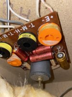
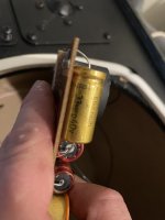
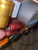
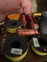
Canton Fonum PC 210 Crossover capacitors

Hi everyone,


I’m wondering if anyone could help me identify the capacitors used in the Canton Fonum PC 210 speakers.
Unfortunately, I can’t read all the values on the original capacitors, and I haven’t been able to find any information online about the crossover specifications or component values.


Any help, photos, or schematics would be greatly appreciated!


Thanks in advance!

Attachments

  • 7de6c26e-385a-4260-b29b-0660e0c28480.jpg
    7de6c26e-385a-4260-b29b-0660e0c28480.jpg
    99.3 KB · Views: 28
  • 1d8fd1ed-d15a-4bd1-9ba7-22d1ff9ac2ba.jpg
    1d8fd1ed-d15a-4bd1-9ba7-22d1ff9ac2ba.jpg
    50.5 KB · Views: 24
  • 7349761d-8a0d-475a-aa5a-265e551d7083.jpg
    7349761d-8a0d-475a-aa5a-265e551d7083.jpg
    68.5 KB · Views: 31
  • fd697f13-5df4-4dee-9c85-c61482ea8533.jpg
    fd697f13-5df4-4dee-9c85-c61482ea8533.jpg
    57.4 KB · Views: 28

Hey All! :)

Hi everyone! I'm passionate about vintage audio and enjoy modifying and upgrading old amplifiers to achieve a rich, warm analog sound. My current setup includes a JVC RX-308 amplifier upgraded with OPA2134PA opamps and a Yyaudio P-037 power cable. I'm running Canton Fonum PC 210 sealed 3-way speakers, which I’ve internally rewired with Neotech STDSPCT-22 silver-plated OFC copper cables using lead-free solder with 3.7% silver content. External speaker wiring is done with 2×2 meters of KáCsa KCE-LS25 cable. For vinyl playback, I use a JVC AL-A151 turntable with an Audio-Technica AT85EP cartridge, an acrylic mat, and Sommer Cable RCA interconnects. I'm always striving to extract the most musical, natural and analog character from these classic components.

Topping D50 DAC does not power on

My Topping DAC D50 does not power on. I tried different USB charger 5V-1.0A and 2.0A.

Did anyone experience the same problem?

I hear it "click" on, but indicator light (display) does not light up. Has anyone any ideas how to get it working?

Thanks.

Attachments

  • IMG_6224.JPG
    IMG_6224.JPG
    100.5 KB · Views: 726
  • IMG_6225.JPG
    IMG_6225.JPG
    77.2 KB · Views: 666
  • IMG_6226.JPG
    IMG_6226.JPG
    108.9 KB · Views: 896
  • IMG_6228.JPG
    IMG_6228.JPG
    170.1 KB · Views: 1,194
  • IMG_6231.JPG
    IMG_6231.JPG
    126.9 KB · Views: 1,271

New Joinee

Hi everyone,

I’m completely new to the world of hi-fi and DIY audio, and I’m really excited to start this journey. I’ve recently developed a fascination with high-quality sound and have been exploring.

While I don’t have a technical background, I’m keen to learn — whether it’s about amps, speakers, or the basics of audio electronics. I joined diyaudio.com to connect with others, ask lots of (probably beginner) questions, and slowly build my understanding of this amazing hobby.


Looking forward to learning from all of you and sharing my progress as I go. Thanks for having me here!

Selah audio designs?

Sad to hear about Rick's passing. He designed some speakers back in 2007 for me. I was wondering if anyone knows who still has access or owns his designs? I'm looking to build some speakers (RS180 + 27TDFC) that he had designed that tonally match the ones he designed for me (RS150 + Peerless HDS). Does anyone still sell his designs or have access to them?

Taramps Smart 3 Bass

Came in with blown power supply. Replaced PS fets, gate resistors and ucc27524 driver.

When I apply power, no remote, the ucc27524 shorts its outputs(pins 5 & 7) to ground with 5.4 ohms resistance. This also happens with the fets removed. I tried another ucc27524 and no change. Parts are from mouser and work in another amp I have here with the same driver(stetsom ex6000eq).

With the ucc27524 removed I can see drive signal on both input pins(2 & 4). I get 12volts on the vdd (pin 6) and ground on pin 3.

After a few minutes disconnected from power the short goes away.

I am at a loss.

how to calculate volume potentiometer value?

Dear friends!
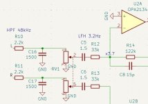
I am assembling a headphone amplifier. I have a question: how to correctly calculate the value of the potentiometer RV1? I heard that it should be about 10 times less than the input resistance of the amplifier. In my case, the input resistance is determined by the value of R12 and is equal to 33k. Then I need a potentiometer of 3.3k? But everywhere where I studied the circuits of similar amplifiers, they recommend a potentiometer value from 10k to 100k.
How to choose correctly?

PS. Input signal goes from PCM2704 DAC (recommended output impendance 10k or more).

Attachments

  • Clipboard_05-27-2025_01.jpg
    Clipboard_05-27-2025_01.jpg
    37.9 KB · Views: 197

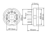
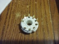
For Sale PCB mount Novar tube sockets

Contracted manufacturer to install 1.0mm pin sockets in Magnoval bases. Tested on 12GT5 Novar tubes.
Money back guarantee if not satisfied with fit. Background link below.
$2.50 each + ship to US, Canada.
Thanks,
Jim

https://www.diyaudio.com/community/threads/real-novar-sockets-inside.397358/#post-7304388

Attachments

  • Big 9 pin dimension.jpeg
    Big 9 pin dimension.jpeg
    13 KB · Views: 244
  • 1.jpg
    1.jpg
    149.6 KB · Views: 222
  • 4.jpg
    4.jpg
    145.7 KB · Views: 232

The beautiful design of SB Acoustics SB17

1000004991.jpg

This are my assumptions, and i am not an audio engineer.

This midrange is not designed for bass even if has lower fs. 30hz
The low fs come from the very lose suspension, believe it or not a loose suspension means eficiency, in a way, because it lowers the qes! Also making it good for ported, making it even more efficient.
Thats why they have such low qes qts.
This means that the coil doesnt have to be denser to achieve lower qes, instead the coil can have thinner wires to achieve a bigger bl (more total coil in the gap) better motor force controll. And with the loose suspension mechanical looses are very low.
This gives it very low distortions

PPI A300 Static

Have a PPI A300 amp connected to the front speakers. I am noticing some slight static when the car is off. When the car is on, there is some slight wining as well. I ran both neg/pos 4 Gauge straight from the battery and have made good connections on both ends.

Can the amp itself be the issue? It seems the input is quite sensitive as well as I have a Xover 2XS in front of the input which I had to turn the gain almost all the way down on it or the volume is very loud at low volume levels on the head unit.

Thanks

SMD components

Hiya,

Looking at SMD components to minimize area on PCBs, but kind of lost in what components to use.

In particular I want to add some caps/ferrites to stop noise/oscillations and wanted to know if I should go for PPS caps for the 10nF/100nF, and what to look for for ferrites. In through-hole components I am using MKP for the caps, ferrite beads on some wire and 150R tantanlum resistors but this takes up more space than I would like (even when using resistors/ferrites vertically.

Not sure what to look for in SMD equivalents. Anyone with experience in SMD components?

Screenshot 2025-05-07 164035.png

Hello! Introductions are in order... :-)

Hello, I'm a new user of this forum and want to introduce myself...

Just recently got back into "vintage" audio (I hate calling it that! it wasn't vintage when I was originally buying / building my set up, back in the 80's-90's). I've dug out my original gear from college and post college, and sadly, much of it is worse for wear. So I'm building a new set up mainly from facebook market place finds!

Anyway, I'm off to post about my BSR EQ-3000 which just quit on me 🙁 Want to see if anyone has any repair tips. See you over there!

Mab007

For Sale QUAD 44 & 405-2

All electrolytic capacitors replaced with quality capacitors of equal value ( higher voltage ) including the large power supply capacitors.

Nichicon muse , Elma silmic , Kemet .

Din cables included

New thermal paste

£450 + shipping ( uk based )

Attachments

  • IMG_9778.jpeg
    IMG_9778.jpeg
    801.4 KB · Views: 186
  • IMG_9777.jpeg
    IMG_9777.jpeg
    813.1 KB · Views: 147
  • IMG_9779.jpeg
    IMG_9779.jpeg
    814.7 KB · Views: 144
  • IMG_9781.jpeg
    IMG_9781.jpeg
    928.5 KB · Views: 146
  • IMG_9780.jpeg
    IMG_9780.jpeg
    886.3 KB · Views: 180
  • IMG_9808.jpeg
    IMG_9808.jpeg
    908.5 KB · Views: 183

LinearX Leap 5 Software Installation Files for 64/32bit Windows (Crossover Shop, Enclosure Shop & Filter Shop)

Hello everyone,

As mentioned in an old thread from years ago, running this program on newer Windows versions is nearly impossible. Additionally, the original installation files are no longer available on the official website and you can no longer purchase it.

After searching through my dad´s old computers, I found .iso files of the program and was able to make it work NO USB KEY needed. This has been tested and confirmed to work on:
  • Windows 11 (64-bit)
  • Windows 10 (64-bit)
  • Windows 7 (32-bit & 64-bit)
  • Windows XP
For proof, I recorded a short video demonstrating all three programs running on Windows 10 (64-bit) -> Video link

Installation Steps

  1. Download the "LinearX Leap5 + FilterShop.rar" uploaded to Google Drive. It contains two folders: "LEAP" and "FilterShop".
  2. Extract the .rar file and move both folders to C:/Program Files/.
  • Inside the "LEAP" folder:
    • LEAP_XVR.exe → Crossover Shop 5.1.0.334
    • LEAP_ENC.exe → Enclosure Shop 5.2.0.350
  • Inside the "FilterShop" folder:
    • Fshop.exe → Filter Shop 3.4.0.808
You can create a shortcut for each executable by right-clicking the file and selecting "Create shortcut" to place it on the desktop.

Important: Fixing the "System Error: Number Decimal Symbol is Not a Decimal Point"

Before opening the programs, it is necessary to change the decimal symbol in Windows from a comma (",") to a dot ("."), as the software requires this setting to function correctly.

Steps to change the decimal symbol:

  1. Open Control Panel.
  2. Navigate to Clock and RegionChange date, time, or number formats.
  3. Click Additional Settings.
  4. Find the "Decimal symbol" field and change it from , (comma) to . (dot).
These steps apply to Windows 10, but the process is similar on other versions.

To simplify the process for everyone, I decided to upload only the necessary files—this way, installation is as easy as copying and pasting folders.

Greetings from Argentina!

Help Sought: Completing My Late Father’s DIY Audio Builds

I'm sharing a slightly different kind of post here, hoping it will find its way to the right people. I’d truly appreciate any shares in relevant places.With great sadness, my family and I recently said goodbye to my father after his battle with cancer. My dad was a very special person, and there’s so much I could say about him—but in the context of this group, there’s one thing in particular that stands out: his deep passion for sound and audio.

Over many years, he acquired an impressive amount of knowledge, technical skill, and understanding, which he used to restore, upgrade, and build a variety of equipment—from amplifiers to speakers, turntables, and more. Before he became ill, he had started working on several projects, but sadly had to stop midway, and now they sit unfinished with an uncertain future.

I’ll be the first to admit—I don’t have the expertise my father had. What I do share with him is a deep love for music, which was one of the strongest bonds between us. But unfortunately, he didn’t pass down his technical skills to me.I’m posting here because I feel that my father left me with a mission—his legacy, if you will. And I’ve made it my goal to try and complete the work he couldn’t finish himself.

I’m looking for a mentor, a guide—someone who can help me understand where to even begin with these projects that meant so much to my father. I’ve attached some photos of what he left behind, in the hope that someone might see the value in this and, out of love for this beautiful world of stereo and sound, help me breathe life back into a dream that’s been paused.

(Just a note: all the items shown in the photos, except for the QUAD speakers, are unfinished projects. The QUADs are functional—I included them to give a sense of the level of investment and dedication my father had for this craft.)

*A pair of Quad electrostatic speakers — rebuilt and fully functional

WhatsApp Image 2025-06-09 at 17.01.16_a9af9731.jpg


*Sony's VFET R0 Diy Kit
WhatsApp Image 2025-06-09 at 16.54.46_33edd913.jpg
WhatsApp Image 2025-06-09 at 16.54.36_745ced4d.jpg
WhatsApp Image 2025-06-09 at 16.56.29_30481cc3.jpg


*JVC TT-101

WhatsApp Image 2025-06-09 at 16.59.25_9c4e1fe0.jpg
WhatsApp Image 2025-06-09 at 16.59.33_d2718b68.jpg

Construction of an ESP P101 power amplifier

Hello everyone,

Following the sudden death of my Sherwood R965, which I was unable to repair, I decided to build an ESP P101 Mosfets amplifier.
I'm going to start with two channels, and will probably add three more later.

So I bought a set of boards from Rod, including:

2x P101c Power amplifier
1x P39c Soft start
1x P33b Loudspeaker protection
2x P245a Mosfet relay

I will reuse the Sherwood R965's case and power supply (600W, +/-56V, 2x27000 uF).

Regarding the P245a (mosfet relay), Rod recommends several references, but I already have components that seem suitable, although I don't have the expertise to be certain.

The mosfets I have are : CSD19536KCS from Texas Instruments

Will they be suitable for this application ?

Regarding the P101c, Rod mainly recommends the ECX10N20 / ECX10P20 references, but these components are difficult to find and obsolete according to the manufacturer, who instead recommends the ECX10N20-W6 / ECX10P20-W6 models.

Again, I assume they are suitable, but I want to be sure...

Thanks in advance to anyone who tries to help me.
  • Like
Reactions: lineup

Mixing Pro and Hi-Fi Drivers in a 3-Way Design – Viable or Problematic?

Hey everyone, I’ve been sketching out a 3-way speaker build and wanted to get your thoughts on mixing pro audio components with hi-fi ones in a single design.

Here's what I’m thinking:

  • Highs: Compression driver + waveguide (pro audio style)
  • Mids: SICA 8 Fe 2.5cp (8" pro midrange)
  • Lows: Instead of a typical pro sub, I’m considering the Peerless by Tymphany XXLS-P830845 (12" Nomex Cone Subwoofer, 8 Ohm), which is more of a hi-fi driver with a lower sensitivity (~87dB).
My question is about making the low end "keep up" with the rest of the system. If I run two of the Peerless subs in parallel, would I effectively gain:

  • +3dB from doubling the driver count
  • +3dB from halving the impedance (going from 8Ω to 4Ω load)
Bringing the system sensitivity from ~87dB to ~93–94dB? Would that be enough to balance well with the higher-sensitivity pro drivers, or am I missing something here? I know there’s more to it than just raw dB—like dynamic response, damping, and matching tonal characteristics—but I’m curious if this is a path worth pursuing or fundamentally mismatched.

Appreciate any insight or real-world experience anyone can share—thanks!

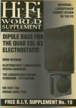
Dipole Bass for the Quad ESL-63 (Hi-Fi World 1995/1996 DIY Supplement)

While watching a video on the history of Quad, a magazine cover showing an ESL63 atop an SL-6000 dipole sub caught my eye.
Login to view embedded media
I was able to locate the articles online and thought other ESL63 fans might enjoy reading them...if nothing else, for historical perspective.
ESL63_SL6000_HiFiW1995.png
Enjoy!

Attachments

Diagnosing and repairing Vibe Slick a0 amp?

Hi everyone,

So I just had my old vibe slick a0 amp die on me. I hadn't realised but it had been running at bridged 1ohm this whole time so honestly surprised it lasted this long. It is rated for bridged 4ohm 200w.

One channel still works but hits protect when you turn it up too much, and the other hits protect as soon as a load is connected (even 4ohm). In bridged it hits protect immediately after being loaded by any speaker even idle.

I've opened it up and the board looks ok, possibly some burn marks on the resistors, or not sure if that's just the black residue that looks like it was there from the factory (attached some pictures)

Anyway I'm thinking to replace the transistors anyway, they are currently k d998 and k b778 transistors. Does anyone know what I can swap them with as I can't find these anymore? I am in the UK. I can find 2sc5200 and it's complement (2sc1943?) for a pretty good price and readily available. Would these work?

If anyone has any other suggestions on what might need replacing or other alternative transistors to use any suggestions would be appreciated!

Thanks
Gershy13

Attachments

  • IMG_20250608_153213.jpg
    IMG_20250608_153213.jpg
    313.8 KB · Views: 64
  • IMG_20250608_153235.jpg
    IMG_20250608_153235.jpg
    485 KB · Views: 64
  • IMG_20250607_211713.jpg
    IMG_20250607_211713.jpg
    879.3 KB · Views: 58
  • IMG_20250607_211709.jpg
    IMG_20250607_211709.jpg
    947.3 KB · Views: 54
  • IMG_20250607_211705.jpg
    IMG_20250607_211705.jpg
    881.2 KB · Views: 55
  • IMG_20250607_211627.jpg
    IMG_20250607_211627.jpg
    976.9 KB · Views: 55

The new DDDAC1794MK3 (DAC and PSU) - Technical and support thread

As I just released the DDDAC1794MK3 series (Dac and PSU) I thought it might be a good idea to set up a support thread for technical and background question, discussion and support.

The release post is here: http://blog.dddac.com/the-new-dddac1794mk3-dac-and-psu/

For those already interested in the construction and installation manuals:

DAC: http://blog.dddac.com/wp-content/up...tion-DDDAC1794MK3-DAC-Version-2.6-rev-1.4.pdf
PSU: http://blog.dddac.com/wp-content/up...ction-DDDAC1794MK3-PSU-Version-2.5-rev1.4.pdf

I am not a great photographer, nor do I have a product photobooth, so here is a somewhat lousy picture of my test set-up:

  • Power transformer 2x12 Vac
  • double DDDAC PSU
  • two AE Chokes (my specs: Amorphe 1H 4 Ohm)
  • DAC Board DDDAC1794MK3
  • Sowter Output Transformers

1713075742704.png


looking forward to some good discussions 🙂

Doede
http://blog.dddac.com/

Been a Lurker Ready to Post

Hello, all. I have been a member for a year or so, but mainly to read messages concerning tube amplifiers and also see what Nelson Pass is up to. I have a friend, V Kung who imports and sells Japanese made tube amps. I'm also interested in learning of attempts to build dipole subwoofers. I have a pair of Quad 988 speakers and am always tempted to add subwoofers to them.

-- Alton

From BoxSim to VituixCAD for absolute beginners

Hi all,

i have tried some years ago the switch from BoxSim to VituixCAD but i have massive understanding problems with that, my impression is that i am getting too old for the learning curve of it.

Here the comment of another thread member, probably younger and less stupid than me:


maybe one of the VituixCAD experts can take a look at BoxSim and add here some comments how to switch from BoxSim to VituixCAD for dummies

there are a lot of DIY folks in Europe that are still using BoxSim, but the import of foreign data is difficult and limited to on axis measurements, Visaton started the development of the program many years ago as incentive to buy Visaton instead of other brands and posted the serious measurement with on axis and off axis data in 5 degree steps only for their own drive units

if you look at the new Purifi tweeter you can see that even in the industry VituixCAD is getting more and more relevant, i wonder when the big players like Seas and Scan Speak will start to offer the measurement data in 5 degree steps to import in VituixCAD

many thanks in advance for your help, Stefano

New to the forum, not new to HiFi!

I've been designing HiFi for 35 years. Built my first DIY amp when I was 14 and still love the hobby!
Having spent a few years away from desigining stuff, I've decided to ditch the corporate ladder and get back to the fun stuff. I'm now taking HiFi a bit more seriously and designing some high-end upgrades and accessories for British HiFi brands (Naim, Pink Triangle, Arcam). I'm also starting my own range.
  • Like
Reactions: r66cort

Roederstein (ROE) EK Series capacitors datasheet

Greetings!

Here is a link to a German language catalog containing the datasheet for the Roederstein EK Series capacitors. See pages 32-37:
https://archive.org/download/katalo...ektrolyt-Kondensatoren - Gesamtkatalog_v3.pdf

I would have added this to the following thread, but it is closed for replies:

To demystify the detail of its body construction: 'The capacitor winding is mounted in a pot-like plastic cup and sealed hermetically with cast resin.' (original text: "Der Kondensatorwickel ist in einem topfartigen Kunststoffbecher montiert und luftdicht mit Gießharz verschlossen.")

view_archive.php

The Audio Circuits Cookbook

I haven't been around much lately because I was working on a new book, this one about audio circuit design. I don't like spamming the forums, so this is a one-time announcement. My Audio Circuits Cookbook published by Focal Press is now available. This book presents more than 80 audio circuits along with extensive tutorial information. It's meant for anyone who wants to design audio devices, but without needing an engineering degree. Full info here:

https://ethanwiner.com/cookbook.htm

Simple High Performing Headphone Amp

Hi All

I just wanted to share this unit gain headphone amp circuit I designed and built it on Sunday.

So far it has exemplary performance and specs considering its simplicity, the built version exceeded my expectations:
Even thought I show a cap in the circuit, if the JFET's are matched the circuit is DC coupled input to output. I built 2 channels and 1 channel has 4mV DC offset andthe other has an 3.4mV DC output offset
The frequency responce is crazy I measured the responce to be almost perfectly flat with 0dB from 10Hz to 1MHz into a 33R resistor.

The specific JFETs isn't critical as long as IDSS is greater than 3mA and they are matched. I simulated with 2sk170GR, 2sk246GR/BL but I built it with 2sk117Y's (the model of the 2SK117 wasn't good).
The output bias current it set by 0.65/R75+R76, in the built version I went with R75 and R76 5R and R50 10R so it didn't run too hot.

I put it in a box last night and listening to Leonard Cohen with it now.

Have to give credit to Nelson Pass for his constant current stage and Erno Borbely for inspiration.

Cheers

Tim

Attachments

  • Headphone amp 3.PNG
    Headphone amp 3.PNG
    14.9 KB · Views: 3,499

Need help increasing input sensitivity of Harman Kardon Citation B power amp

I am trying to use a Citation B power amp (circa 1964) in place of my Marantz 9 tube amps as my "summer" amp here in the desert.
I noticed the sound to be good, but the sensitivity is less. The Harman Kardon is rated at 1.6V input for rated power. Curiously, I can't find the input sensitivity specs for the original Marantz 9's. It is not on the brochures I've seen from the company. The reissue from 1996 does list the input sensitivity as 1.3V into 100K ohms.

Looking at the schematic (attached), I see R2 (left channel) and R36 (right channel) in the input part of the circuit which is 2200 ohms. Would this be a good place to start? What value resistor should I use? I may install sockets on the circuit board to experiment with different value resistors.

My preamps are Marantz 7 and 7T. I would like the Citation B to mimic the 9's input sensitivity as close as possible.

Thanks much!

Attachments

  • Citation B schematic.jpg
    Citation B schematic.jpg
    367.4 KB · Views: 63

Lii Song Canada?

Hi ive been waiting for over 6 months for some f-18 drivers to arrive. Ive reached out several times by email with no response, but have phoned a few times and go a next week they should be sent out response, for the past few months. Now they have closed operations in canada...
My questions are is anyone else in the same boat? Is this normal for lii Song?

Simple, no-math transformer snubber using Quasimodo test-jig

A power transformer snubber is a wonderful thing for reducing or eliminating RFI from rectifier-induced LCR ringing. Unfortunately it's a huge pain to design and optimize a snubber. First you have to measure the transformer's leakage inductance and secondary capacitance, at about 100 kHz, which is not especially easy. Then you have to estimate the capacitance of your rectifier(s), which does not always appear on datasheets. Finally you plug these numbers into a formula that spits out snubber values -- and then you hope it's all correct.

Shown here is a little test jig called "Quasimodo the bell-ringer" which makes this process a great deal simpler. Quasimodo connects an actual snubber across the transformer, smacks the transformer to make it ring, and you observe the ringing on an oscilloscope. Then you adjust a (25 turn) potentiometer on the jig, watching the scope to find the setting which completely damps out all ringing. And you're done! Just use the same snubber values in the end product, as you used on the test-jig, and success is yours. (The 25 turn trimpot is socketed for ease of measuring the final resistance that gave perfect damping).

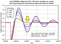
Attached are some scope waveforms showing a Quasimodo jig driving an Avel Lindberg toroidal transformer (from the Akitika GT-101 power amp). I set the trimpot to 5 different resistance values, and got the 5 traces shown. When the trimpot was removed from its socket (R = infinity), I got the black trace. A setting of Rtrimpot = 109 ohms (red trace) gave "critical damping" with no ringing: see yellow arrowhead.

Quasimodo gave an optimum snubber having critical damping (Greek letter zeta = 1.0), without requiring any calculations and without measuring the transformer's inductance or capacitance. It is a quick procedure, too: set Rtrim to max, observe waveshape on scope while reducing Rtrim, stop when all ringing is completely damped out, remove Rtrim from socket and measure it with an ohmmeter. About 3 minutes from start to finish.

This Avel Lindberg transformer has dual primaries for 115V/230V operation. So I configured the primaries the other way and ran Quasimodo again: figure attached. Not surprisingly, the optimum snubber for 230V operation is (slightly) different than the optimum for 115V operation: 120 ohms versus 109 ohms. Plus or minus the error tolerance of my ohmmeter, of course!

I've also attached a .pdf note that contains more details, schematics, construction tips, user guide, more "Quasimodo in action" scope photos, plus a bit of theory and a list of references.
EDIT 1: I had a small number of extra PCBoards + kits of all parts, which I sold at my cost, in October - December, 2013. They are all gone now, and I have no plans to sell any more. I encourage any energetic and enthusiastic diyAudio member to organize a Group Buy, using the PCB Gerber files and Bills Of Materials I provide in this thread. "CheapoModo" (a low cost version of Quasimodo) kits and PCBs are available in the Vendor's Bazaar, here.

EDIT 2: I have attached the PCB Gerber files and the Bill Of Materials, for both boards (V3_SMD, and V4_thru_hole) right here, to post #1. So now they are very easy to find!

EDIT 3: (April 2022) I just stumbled across this "Yes Math!" application note from Texas Instruments, which calculates RC snubbers to eliminate ringing from switch mode power supplies: (link)

EDIT 4: If you don't yet own an oscilloscope, post #2540 of this thread shows a cheap (USD 40) little scope toy which works for Quasimodo.

EDIT 5: Answers to frequently asked questions:

  1. Build guide for V3 (SMD) is found in post #27
  2. Build guide for V4 (thru hole) is found in post #103
  3. 2 hour build time, quick-and-dirty Quasimodo on solderless protoboard (no PCB!) is found in post #18 and in (the CheapoModo thread)
  4. Substitute parts recommendations are found in the Bill Of Materials
  5. How to choose a MOSFET besides the ones in the BOM, is found in post #175
  6. How to check your own BOM before purchasing components, is found in post #203
  7. diyAudio members who have ordered their own sets of PCBoards from a PCB fab, using the Gerbers provided here, include: gazzagazza, luvdunhill, Borges, stormsonic, cwtim01, normundss, dsolodov, EUVL, kissmurphy, stephengrenfell, Piersma, SyncTronX, yoaudio, andrensairr. You can PM them to find out how easy or difficult it was.
. .

Attachments

Hypex Nilai: Is it possible to bypass the onboard input buffer?

After much consideration, I have decided to use the Hypex Nilai platform for my new Class D amp. I was wondering if it’s possible to bypass the internal input buffer or if this is even a good Idea. I believe that they use a type of differential circuit, I probably don't want to mess with this. I will be using a Silver Rock passive TVC preamp and will most likely need more than the 29dB of gain that is offered on the board.

My idea is to use a tube (or discrete op-amp) buffer and gain which will allow for over 30dB of total gain. Is this a good approach? having 2 buffers does not seem to be the simplest solution but bypassing the internal buffer may not be possible or recommended. Any ideas?

Thank you, community!

G

Home grown digital sub filter

I need some brain gymnastics this weekend, so I was thinking of designing (from scratch, of course) a digital sub filter for the sub woofer I'm currently working on. I have a Teensy4.1 with an audio shield that should be up to the job.

My DSP-fu is a bit rusty, though, so maybe someone can do a sanity check?

Filter. I want to use a FIR due to its linear pass band phase (and therefore constant group delay). Unfortunately, very low frequency LP filters require extremely long FIRs, so I'm going to use the old decimate-filter-interpolate trick. I first decimate by 5, apply my filter, but with a 5 times higher relative cutoff frequency. Then I filter it again to interpolate. I experimented a bit it Octave, and it looks like 100 taps for the first filter and 50 for the second one yields decent results without using too much compute power. I'm not too worried about the aliasing bumps in the stop band, as they sit at about -55dB.
IMG_1955.jpg

1749822536526.png


Next I need some kind of phase correction. And correct (no pun intended) me if I'm wrong, but it's really the group delay and not the phase I want to correct. So instead of fiddling with all-pass filters, I should just use a simple digital delay, right?

And yes, I know I can buy a perfectly good module for this at AliExpress for less than a the price of a cup of coffee. But what's the fun and learning experience in that?

Greetings all

Hi,

My name is Gavin from Australia. I’ve wanted to build my own speakers for years. Bought a few books, enough to scare myself off a new build for errr decades. Tinkered around converted two way sealed to a 3 way etc. but never built new.

Finally decided I’d build a kit set, but couldn’t find a kit I liked. Almost pulled the trigger on some open baffles with servo sub, but the sub had known issues with 240V. Scared me off, kept looking. Don’t even know if I like open baffles - never heard them.

Finally landed here because of the OSMC. That bought me here. Yes, finished. Thought I’d post the obligatory glory shots, but I’ll add this to the OSMT thread once permitted. But I’d like to thank all those that contributed so newbies like me can tackle their first speaker build. Yep numero uno.

Now I have some awesome speakers I need to an amp.. here I am.

Gavin

Attachments

  • IMG_1260.jpeg
    IMG_1260.jpeg
    700.2 KB · Views: 54
  • IMG_1259.jpeg
    IMG_1259.jpeg
    687.7 KB · Views: 49
  • IMG_5701.jpeg
    IMG_5701.jpeg
    811.7 KB · Views: 45
  • Like
Reactions: mz543578854 and stv

Self cutoff issue moding a JTM45 amp clone

Hi,

After 30 years using my JTM45 clone (Echolette BS40 from 1968), I've finally decided to apply all the mods I had in mind for so long.
Since a recap was needed, I had to screw up stock german build anyway, let's do it deeply.

I'm mostly cloning a JTM800 preamp, with all stages chaining in series, cold clipper on V1B, warm stage before the cathode follower and attenuators between stages
Preamp seems working ok on scope with no power tubes.

Next mod in my mind is trying to improve the amp's voice, moving master volume from pre to post tone stack. The stock pre is on the cathode resistor of the cathode follower, it tends to scratch a bit event with a new pot, tone setting gets screwed on volume change, and tone shaping is limited.

Problem occurs when I put a 100k resistor on cathode, and a 650k pot between the treble cursor and the grid from the inverter : amp self cuts off at 20/25W (dummy load), after a short period of sort of self oscillating. On Marshall schematics, vol pot is 1M, I don't have any. I doubt it really solve anything looking at the impedances involved in the tone stack.
I reverted back to pre tone stack master and problem disappears, but I'm not satisfied at all, especially because I don't really understand what's going on. I suspect something related to NB, but don't took time trying to disable it before revert back

Any thoughts ?

Thanks

Attachments

  • Echolette_BS40.jpg
    Echolette_BS40.jpg
    131.4 KB · Views: 95

Harvesting CDM9/44 laser assemblies...

** Cross-posted on Pink Fish Media **

Just picked up another 2 of these Kodak PCD-860 Photo/CD players to add to my collection (I now have 4). A perfect supply for CDM9/44 laser assemblies, which the laser assembly is identical to the CDM9/Pro laser fitted to my 2 Naim CDIs (and many other high end players).

They are a perfect source of low mileage lasers - a photo cd player was something that never really caught on, so any out there are almost bound to be little used. Three of the 4 I have all displayed the exact same faults;

- Tray belt stretches so doesn't close tray fully
- This means laser mech is not in right position and it slams the upper disc clamp down onto the disc platter off centre, pushing the shitty plastic platter down onto the mech

For the 2 I've just bought I have just forced platter up .2-.4mm, fited a temp belt to test laser - both working perfect. Now I strip the lasers and throw the rest away (a little guilty for the landfill, but apart from laser they're a crap machine!).

Look at these belts - proof of lack of use for a few years 🙂

51567780162_baf7b5ac89_b.jpg


Sharing this info now as I now have 6 suitable laser head donors for my 2 CDIs - should see me out for my life 🙂 If you're after good 9/44s, keep your eye out for these (recent 2 cost me £17 each, they're always cheap).

51569505940_3dfdd24889_b.jpg

51568817893_f57e21f767_b.jpg


Richard

DAC PCB for DSP

After 20 years I want to upgrade my active crossover (dcx2496). I do not need more functionality but upgrade noise and thd specs.
Looking around I find dbx pa2 and venu360 but they have almost the same specs.

So I decided to build an active crossover/dsp myself with some ready made modules(pcb).
DSP I like to use an adau1467 processor using it for 2 channel in and 8 channel out.

For output dacs I have seen boards below, does anyone experience with them?

  • CS4398
  • PCM1798

I think the pcm1798 with OPA 161X opamps has the best specs.
For that price I can not build it myself.

IMG_0971.png


IMG_0972.png

Da-capo issue (John W?)

John I was wondering if you came to any conclusion about the pink noise from the da-capo DAC from the post on the forum middle of last year.

I also have a Da-Capo which creates the same pink/white noise sound, with a hint of the music behind it, after a period of being powered up (doesn't seem to make a difference if it is in standby or not, just the power being plugged in).

The DAC has the HDCD filter fitted (so isn't the 1307 filter issue that you mentioned).

I have tried re-seating the filter module and moving the Input card to a different slot. Neither have made any difference.

Funnily enough about 4 – 5 months ago a Da-Capo came up for sale that must have been one of your development ones. The serial was no 1 and it had a dedication to your wife actully on the circuit board. If I had seen your name on these forums before now I would have let you know as it sold for silly low money…

Lastly I wondered if by any chance anyone might have a copy of the original Da-Capo instruction manual at all? I would really appreciate a photocopy of it (been trying to get one for ages), I am also looking for a Cardinal instruction manual as well…

Does anyone know the dip switch settings for the HDCD filter (or will I only get intelligible sound if I have used the correct setting)

What transport was the Cardinal based on… Yes I know the drawer etc is some bespoke low vibration material etc… but I guess the laser and motors etc. were taken from a commercially available Transport… It would be of immense help as I could then track down some s/h really cheap units that used the same laser and motors etc for future spares.

John can you remember if the cardinal produced performance figures (jitter etc.) better than most other transports produced, or is it just good figures for it's era?

Lastly is there any other transports that use a compatible clock lock to the Da-Capo DAC? Just wondered because at some point if the cardinal broke and it can’t repaired it would be good to know of any other transports that would work with the clock lock connection on the DAC.

Thanks for any info that can be offered.

John H

PS my Cardinal accepts CD-R’s without any drama (including the cheapest of the cheap CD-R’s), I haven’t tried RW’s but will later tonight.

Easy way to find port (or passive radiator) tuning frequency. Test your subwoofers

Here is the method
1) Install Spectroid app on your Android phone from Google playstore
2) Ensure there is relative silence while doing this test, we want to keep the noise floor down.
3) Prepare to run frequency sweep from youtube Login to view embedded media This is a sweep from 25Hz to 150Hz. You may use any other way of sweep if you want to go lower than 25Hz. Pause the video at start.
4) Bring your android phone mic as close to the port as possible keep 1 cm of distance but dont touch the speaker or sub with your phone. The idea is that the mic should mostly catch the audio from port only and other sounds should appear as noise coming from far.
5) Start the app
6) Run the sweep from youtube, when it completes, notice the peak in response in bass in the red curve of the app, that's your tuning frequency
7) Repeat above to be sure.

Note:- Android phone mic is not a good way of measurement but for this purpose, it works

Below is my speaker's 60Hz tuning
JBL-60Hz-Port.jpg

Hope it helps.

Warm Regards,
WonderfulAudio
  • Like
Reactions: Freedom666 and stv

Adding a tweeter to a full-range

I'm using 4" full-range whizzer cone speakers in my bedroom. They operate normally. No lack of treble. However, one day, I found the NOS tweeters of the same series with those full-range are being sold. I think what if I buy and add them to the 4" full-ranges.

Of course, the HPF for the tweeter is required. But, how about LPF for the full-range, isn't it required?

If so, the x-over point might be set at around 4-5kHz (no problem). But, if not, which means running the full-range (closed) to 20kHz as usual and assigning somewhere upper frequency for the tweeters to handle, then, what frequency should be set for HPF of tweeters?

PS. I have a DSP in my system so I can actively control x-over.

704 front.jpg
  • Like
Reactions: ayooper

New transistor source

Hi everyone

I've been working professionally with solid state amplifiers for over 3 decades , and have been surprised by the sudden surge of devices going EOL. I believe that traditional class AB amplifiers are not going away, but are transitioning away from the mainstream to a boutique market. Valve amplifiers saw this happen a long time ago. With that said, there are a lot of high end solid state amps being built, and specialized parts sources are out there to supply them. I would like to list a number of sought after device type easily available, in some cases with a different part number.
They are available from Profusion plc in the UK. We have verified samples of everything listed here in pro audio gear made by LAR audio systems.
LAR audio is reason I had to locate some new sources.
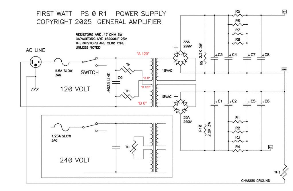
KEC DEVICES (Korea Electronics Corp.):

KTA1381 / KTC3503 300V FAST VAS STAGE TO126 Replacement for the EOL ON devices really fast high voltage VAS
They should be in stock by Jan.

KTA1837 / KTC4793 230V VAS / DRIVER TO220 Replacement for toshiba 2SA1837 / 2SC4793 , good VAS and driver , in stock

KTA1700 / KTC2800 160V VAS / DRIVER TO126 Replacement for 2SA1220A / 2SC2690A , GOOD VAS and driver in TO-126
They should be in stock in Jan

KTB2640G / KTD1640G 150V 130W FAST DARLINGTON OUTPUT TO3P N Replacement for Sanken 2SB1647 / 2SD2560 improved SOA, in stock
This is a really nice output device for simple hifi amps

KTA1943A / KTC5200A 230V 150W WIDE SOA FAST OUTPUT TO3P L (TO264) This is an enhanced version of Toshiba devices, almost identical to 2SA1302 / 2SC3281 in every way , but higher voltage rating.

Unisonic This is not the most serious sounding name for semiconductors, but it is an established OEM supplier in Taiwan.

2SD669/A / 2SB649/A The TO126 versions are a good substitue for 2SA1220A / 2SC2690A There is some confusion about power ratings on the data sheets because they come various packages, including SMD, and the rated power is in free air We have verified that the SOA curves for the 2SD669A apply to all TO126 devices when on a heatsink.

2SA1837 / 2SC4793 The TO220 versions are also like the old favorite, but they are available in various case styles.
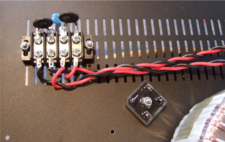
I may have post this in the wrong area, but searching threads, most appeared to discuss a specific need for a specific project. I hope I have been helpful to continue on with the construction of fine Transistor amplifiers.
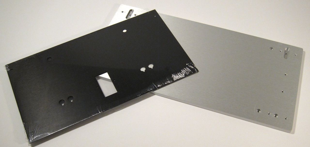
For Sale Universal Power Supply PCB for TO 220 Voltage Regulators

For lower power projects like preamps, headphone amps, etc. I like to use power supplies with TO220 voltage regulators.
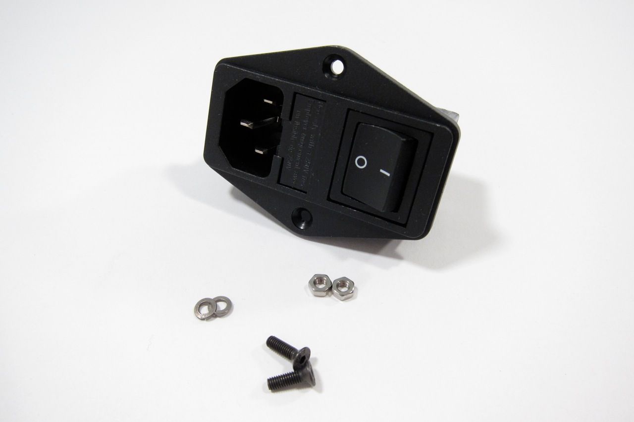
I designed a universal board for this.
To power a recently built OREAD, among other things, I had some new supply boards made and now have some spare boards for sale.
The board can be used with TO220 voltage regulators like LM317/337 and 78xx/79xx or others with the same pinout.
It also allows the use of: fuses, RC-snubbers for transformer secondary windings, rectifiers like 1N54xx for full 1.5A current, CRC filtering, suitable heatsink,
soft start for output voltage.

The circuit below shows values for +/-15 volts output. A BOM (example/proposal) will be sent to buyers via email.

NT218_r10.jpg NT218_r10cu.jpg

NT218_r10pcb.jpg

this version sold out. new version available, see last post.

If interested: Email/PM me
Projects by fanatics, for fanatics
Get answers and advice for everyone wanting to learn the art of audio.
Join the Community
508,507
Members
7,922,558
Messages

Filter

Forum Statistics

Threads
407,892
Messages
7,922,558
Members
508,507
Latest member
Boc610