Introducrion

Hello. I have been a member for a few years and am only just now interested in some opinions regarding my amp. I am currently running a Rotel RB 1095 and have an RB 1090 out of comission due to A faulty power switch that sticks and I am unable to at times either power up or power down. I have A Rotel RC 1082 preamp. Dynaudio Contour 3.4s with upgraded tweeters from Esotec to Esotar 2. Read where quite A few had made this change with great results. No tweak to the crossovers necessary. I use A Blusound Node to stream with roon, A Rotel RCD 1072 CD player, Technics 1200mk 2 turntable with an AT VM95ml cartridge, Denon 3500H that I run preouts for movies occasionally. Center is A Dynaudio Contour SC and matches the mains. Will be shortly putting an Esotar tweeter into that as well. So nothing ourageous compared to some but it is meeting my needs and still puts A smile on my face when I turn it on. All purchased second hand and has been great for approximately 4 years. The only new piece purchased is the Blusound. Other than that I am not sure how these intro's work. I am married with two kids 35 and 33, RN for over 25 years, moved from Home territory in the suburbs of NY to Mesa Az in 2000. This is not the time of year to be here, 112f today.

Ever wanted to be a beauty pageant judge?

Well, then here's your chance!
After collecting RCA 808 triodes for over fifteen years I finally have three pairs, enough to build a SET with them.
808 is a close relative to the much more common 811A and must be pushed far into class A2 in order to produce any useful output power.
The easiest way to do this is by using a decent-sized power tube as a cathode follower, direct-coupled to the grid of the power tube.

Here I have picked a selection of tubes that should be up to the task (807, 6L6GB, 6AV5GA and PL36) and now I would like your opinion about which one that would be the best visual match to the 808 (the one to the left of the 807).

pageant.jpg

Peerless TC6FD02-04 ( 2" Full-Range ) + HB-05F-ML3

Peerless TC6FD02-04 installed in a double bass reflex.
Cheep bass but great mid and high.

HB-05F-ML3-05.jpg


Login to view embedded media

Attachments

  • HB-05F-ML3-04.jpg
    HB-05F-ML3-04.jpg
    109.2 KB · Views: 223
  • HB-05F-ML3-01.jpg
    HB-05F-ML3-01.jpg
    158.3 KB · Views: 245
  • HB-05F-ML3-02.jpg
    HB-05F-ML3-02.jpg
    108.1 KB · Views: 234
  • HB-05F-ML3-03.jpg
    HB-05F-ML3-03.jpg
    49.7 KB · Views: 186

Design for 18 Sound 18NLW9000

Any cabinet suggestions for the 18 sound 18NLW9000?

Eighteen Sound 18NLW9000 - 18" Subwoofer

I have two that need a new home.

They're currently in a xoc1 style tapped horn with cone compensation made out of OSB3. They've lasted for 7+years but they're now falling apart unsurprisingly so looking to build cabs out of baltic birch ply.

I've looked at Arts Keystone Tapped Horn and the Paraflex Alt-config or Classic C.

People seem to have reservations about the light cone in these designs resulting in unwanted distortion although I haven't had this issue in the current cabs.

I was wondering what would be the ideal cab for this type of driver with high xmax, high power rating, light cone, and decent BL .... Reflex possibly?

What would you use this driver for if you had one lying around?

Group Buy for Curve Tracer Matched 2SK3497 Pairs at 55°C

As mentioned earlier, we are offering 18 pairs of curve tracer matched 2SK3497 at 55°C for lucky owners of Semisouth pairs.
https://www.diyaudio.com/community/threads/another-sjep-giveaway.394988/post-7251222

These were matched from a batch of 60 devices, so the yield is only 60%.
Matching is 4mV Vgs at 1.25A, and Vgs to 5%.
The majority of them lie way below those limits.

Price is, as mentioned, 400 HKD a pair including PP fees and Registered Air Mail (packet).
We only deliver FOB, and are not responsible for any postal losses.
Registered mail is not insured. But HK post has been proven very reliable in the past.
What happens at your end, they have no influence though.


Patrick

Tubelab SPP first timer build

From recommendations from several people i've now moved onto serious thoughts to build the Tubelab SPP amplifier.
http://tubelab.com/designs/tubelab-spp/

Please keep posts only about the Tubelab SPP amplifier, the recommended components, as the design gives in the parts list.

Your thoughts, suggestions, experiences and cases to use, are welcome but based only on the original design http://tubelab.com/designs/tubelab-spp/parts-list/

I'm based in southern europe, so i would like to try and source components etc from the least amount of sources, to avoid courier costs and import duty.

I'm aware of these sources: -
https://www.rapidonline.com/ https://primarywindings.com/ https://www.digikey.co.uk/ https://eu.mouser.com/

Massive

This amp has audio for a slight second.There is no oscillation after the audio stops.The port in the pic got damaged while I was removing the glue,anyone know the value and the function of it?

Attachments

  • IMG_3032.jpeg
    IMG_3032.jpeg
    516.1 KB · Views: 54
  • IMG_3030.jpeg
    IMG_3030.jpeg
    424.2 KB · Views: 56
  • IMG_3028.jpeg
    IMG_3028.jpeg
    521 KB · Views: 57
  • IMG_3029.jpeg
    IMG_3029.jpeg
    556.5 KB · Views: 52

USB Audio Amplifier (PCM2902/NE5532) schematic

Hello,

I designed an USB Headphone Amplifier in KiCad, inspired by this tutorial USB Headphone Amplifier Design Walkthrough - Phil's Lab #101, inspired Douglas Self.
The PCB works (I fixed some minor errors in the uploaded Schematic), maybe it is helpful for someone 🙂

Nevertheless I have some questions:

Without Headphones connected/music playing the board draws around 270mA from the USB power supply. When R8 (20R) is removed, current draw is ~0. In this state the voltages for the "+16V" and "+15V" net are ok (measured 15,9V and 15,1V), but with R8 connected, voltages drop to 14,7V and 14,5V, so only 200mV drop over the linear regulator :/ Decreasing R5 did not help, even if the "idle" voltage of the boost converter is set to >>16V it breaks down when R8 is connected (there is a 1,4V drop over this 20Ohm-->70mA). The USB power supply could deliver 2A@5V.

Any ideas how to fix this? This also makes the device not really usable on a phone because it draws a lot of current from the battery.


The sound in general is quite good, maybe a little bit too "bright" for my taste, it could be some distortion in the higher frequency range (frequency response is completely flat), but I dont have access to a spectrum analyzer to evaluate this. The gain could be a bit more for 600Ohm Beyer DT880, I am mostly using the 250Ohm Version and for me it is more than enough.
The DAC (PCM2902) is quite old (but easy to implement), I will probably switch to ES9039Q2M and add SPDIF --> analogue conversion which is missing here (SPDIF goes only to USB atm).


Any suggestion how to improve here? 🙂

Attachments

Speakers for a computer with full-range driver 2-2.5"

Speakers for a computer.
Hello everyone! I like to make various acoustics based on ready-made projects on the forum.
Now I am looking for a project to make compact speakers for a computer on a 2-2.5" full range driver
with dimensiones the box up to Width 10cm (4 inches), Height up to 20cm (8 inches), Depth up to 15cm (6 inches).
and power them from an amplifier based on the PAM8406.
I'd be glad to receive any links to finished projects!
I also really liked the projects from Japan by a user named Nandappe!
But what if I missed something?
Thanks in advance to everyone!

I Found It

Dear all,

I'm a bit of an ebay hound and recently I "accidently" bought an amplifier.
In researching the amp I find this website and find out that there has been a 10 year discussion trying to track the amplifier down.

I am posting this introduction so I may get into the forum and tell all of these people that I have found what they are all looking for.

Its a 1970s Linear T40/60 Mk1 - I paid £50 for it in a ebay auction as the only bidder.

Photo include.

Cheers.

Knox

Attachments

  • LA.jpg
    LA.jpg
    761.4 KB · Views: 46

Greetings from Canberra, Australia

Since my retirement seven years ago, I have had the time to tinker with audio gear. I have purchased used audio gear from a local auction house and managed to get some working again while a lot is still sitting in the garage while I figure out how to repair them. I also got one of those tube amplifier kits from ali to build and it does work OK. That gave me the confidence to carry out some of the Skunkie Design mods to my Willsenton R8.
Recently I got the brand new drivers and crossovers for the old Jaycar JV60 speaker kit from said auction house (Jaycar is an Australian electronics hobby chain similar to Radio Shack) but there was no accompanying cabinet kit so I am going to have to build those from scratch.
So basically I am a HiFi enthusiast keen to learn how the gear works.

The difficulty or otherwise of sourcing an audio output transformer

Hi. I bought a valve radio chassis (McMichael 501AC) and it came without the loudspeaker (would have been 30 Ohms) and audio output transformer. The power output is a push-pull arrangement, and the circuit shows a pair of KT61's. The valves in the set I've bought are a pair of EL33's. I'm not sure if any circuit mods were made to accommodate these EL33's. Anyhow, is it likely going to be difficult to source a suitable audio output transformer? Thank you. Rich

Need help again … this time with this HiVi planar tweeter

I've got just about everything else figured out now. Thanks to everyone who has been helping me so far.

I have this HIVI planar tweeter whose frequency response is just nutzo. I have seen this when attempting to use planars with traced data and thats why I usually avoid them. This time I took a chance because it seemed people like these a lot.

https://www.parts-express.com/HiVi-...mXZCI_35z_JCkaqh9T4PSTB3WzmOOd2xoCWmwQAvD_BwE

I'll attach the raw REW measurement data
Basically I have this huge peak at 9k. I guess I could try to take care of it with a gigantic notch filter but I have other peaks and valleys. This is pretty far from a flat response. Its also wayyyyy more sensitive than the other two drivers. I'm going to need a beefy lpad to tame this beast.

Is there something wrong with my measurement or is this just what it is?

PS. I just started the crossover like 5 minutes ago so thats why nothing is even close to right at the moment

Attachments

  • HiviTweeter.zma.mdat
    HiviTweeter.zma.mdat
    903.4 KB · Views: 32
  • Hivi 0 Degree.frd
    Hivi 0 Degree.frd
    6.5 KB · Views: 36
  • Screenshot 2024-07-16 102225.png
    Screenshot 2024-07-16 102225.png
    108.8 KB · Views: 63
  • Screenshot 2024-07-16 102204.png
    Screenshot 2024-07-16 102204.png
    62.7 KB · Views: 66

Alternative method for L-Pad

In three-way speakers design, if we'd like to reduce the SPL of the midrange and tweeter, it could be easily achieved by adding the L-Pad circuits to the drivers. However, some people used to advice the resistors should be used as minimum as possible because they would introduce loss, and some distortions, to the system. Hence, I found the alternative method that is to use a single resistor on each driver and redesign the whole crossovers.

original.png


modified.png


As can be seen, the modified crossovers could provide the same result as using the L-Pads on midrange and tweeter.

I wonder which way is more suitable between adding L-Pads to both midrange and tweeter, or redesign the crossovers and use only single resistor for each driver?

Chassis venting recommendation for Aikido octal and PS-21

Hello, can anybody here recommend chassis venting ideas? I am mostly worried about the PS-21 and the heat sinks. Looking at the chassis you will notice that everything is mounted to the top plate. the transformers have been mounted with very tough 25 lb mounting tape and I will be using foam as a wedge on the bottom panels.

Attachments

  • IMG_0538.jpeg
    IMG_0538.jpeg
    555.8 KB · Views: 105
  • IMG_0539(2).jpg
    IMG_0539(2).jpg
    484 KB · Views: 100

LDSP - audio optimised i.MX 8M Plus QuadLite

Today I've been working on a new DSP board that should allow for some really interesting new projects.
I have exposed the maximum audio and clocking I/O available on the i.MX 8M Plus QuadLite MCU - currently $38.
Target is low latency Linux kernel with custom kernel/linux DTS overlay config and an app to configure the audio I/O.

1674851377720.png

i.MX 8M Plus QuadLite "MIMX8ML4"
4 x 1.8Ghz Corext A53
6GB LPDDR4
1 x MicroSD card slot
1 x mini pcie slot for wifi / bluetooth
1 x Ethernet with AVB,1588
1 x Ethernet with AVB,1588, TSN
13 x I2S interfaces (26 ch in/out) - 8ch DS512 supported on some pins.
Header for upto 4 master clock Inputs
S/PDIF Tx & Rx
32 channel ASRC with an insane pre filter unit - upto 128 filters per channel or 128-taps.
HDMI 2.0a with eARC for up to 16ch/192kHz or 32ch/48kHz LPCM
Dimensions : 125mm x 58mm
  • Like
Reactions: Naturlyd and AxisB

Pocket Diamond Buffer (PDB) Headphone Amp

I’m working with Jhofland to develop a new Class AB version of the Pocket Class A (PCA) headphone amp in an Altoids tin called the Pocket Diamond Buffer (PDB). It will use the Diamond buffer discussed in another thread combined with an OPA1642 for the voltage gain. The buffer will be inside the feedback loop of the opamp for a composite amp. This will be a state of the art headphone amp in a nostalgic DIY package. The power on/off will be controlled by the click on the volume pot (same as PCA) but a MOSFET had to be added to turn on and off the negative rail. Power will be two 9v (rechargeable or alkaline) batteries. Being Class AB, the power consumption should be way less than the PCA.

Here is first draft of layout. It’s very dense with 16 actives and an IC:
IMG_5937.jpeg


Here is top level schematic:
IMG_5939.jpeg


Individual buffers look like this (values TBD for operation at lower impedances):
IMG_5940.jpeg


For those unfamiliar with the PCA, here is what I am thinking it will resemble:
IMG_5863.png


Stay tuned as this is still early stages. We need to make a prototype and test and verify still.

Update - PCB and component location stuffing guide.
Bottom:
IMG_5979.png

Top:


IMG_5942.png


* Important* please change C105/106 to 47pF NP0/C0G. 470pF causes oscillation at 6MHz.

Kyocera KGM15ACG2A470FT is a good replacement.

Technics SE-A1 biasing

Hi all. Just finished repair of A1 with blown channel. Going through after-repair adjustments I am unsure which bias shall be sufficient for Class-A section. In absence of service manual, what we have there is just emitter resistor 0.68 ohm per device, showing 0,8volts across both resistors (emitter to emitter). Simple calculation is 0.8/(0,68+0,68)=0.588 times 8 - there are eight pairs of output devices. Got 4,7 ampere in total or 0.6A per pair. Rails are +/- 10V. Low? High? Or its normal? Maybe someone have working amp and be so kind to measure?

some pics just for reference

Attachments

  • IMG_1032.JPG
    IMG_1032.JPG
    433.5 KB · Views: 190
  • IMG_20240525_194313.jpg
    IMG_20240525_194313.jpg
    505.3 KB · Views: 168
  • IMG_20240525_194332.jpg
    IMG_20240525_194332.jpg
    655.8 KB · Views: 196
  • IMG_20240525_202353.jpg
    IMG_20240525_202353.jpg
    558.1 KB · Views: 318

Cone surface area

Hi!

It seems the usual method to calculate diaphragm area for a cone driver is to measure it's diameter (plus some part of the surround) and derive it from that. This way, we get the surface area of a flat circular sheet. But hey, cones are not flat circular sheets.

Why is this important?
For example, to get Vas value of a driver, we need to know its diaphragm area, because Vas derived from that and there can be significant differences if we use different diaphragm area for the calculation.
Usually the larger the driver diameter the deeper its cone, so larger the differences if calculate the diaphragm area with flat circle area vs cone area method.

So why the flat circle method instead of real cone area method?

Do You Really Need 2 Vrms From Source?

Hello DIY friends, I have an interesting story for you all.

Last night, I was discussing with some HIFI friends total system gain structure. I was using Pano’s post on calculating the total gain of his system, mainly because one of my friends was concerned that his new pre-amp project wouldn’t have enough gain. His DAC has a maximum gain of 12db, ie, 2v. His pre-amp project has 6db 1v of gain, and his power amp, has approximately 19db 2+ v.

To me, this sounds like a lot of gain, ie meaning that the pre-amp at full power, you have to attenuate the signal, unless you want to make your ears bleed. Btw, his speakers are 93db efficient.

Well that got me thinking of my own setup. I have a Wiim Mini streaming connected via Toslink, to a topping D30. The topping has 2v output, 12db. My current pre-amp is the ACP+, which has 9db, according to nelson’s article. Power amp is the new Aleph JZM, which I assume, has the same gain as the original, ie, 19.6 db. As for my speakers, currently I have some Emotiva B1+.

Okay back to the so what here. Well, this got me thinking that I probably have a lot of gain, having to attenuate a lot of signal via the Acp+ volume pot.

I’ve been thinking a lot about attenuation, and how you lose signal when you attenuate. I blame Zm for putting those ideas in my head, after learning about the Iron-pre/Iron pumpkin.

Then I remembered something interesting about the wiim mini, a small feature, hidden in the software.

Side note: The wim mini has both toslink, and headphone jack output. I mostly use toslink to feed to my topping d30.

So back to the software feature. In the settings, you can digitally changed the output vrms. Either, 2vrms, 1vrms, 800mVrms, 500mVrms, 200mVrms for the headphone jack. Hmmm well that’s interesting!

Searched to my stash for a headphone jack to rca cable. Unplugged my topping D30, connected directly to wim mini.

Started at 2vrms, full blast on ACP+. Had to turn the pot to 9 a clock. Changed it on the fly to 1vrms. Turn the volume to 12 a clock. Load, but more detail. Eventually, I turn it all the way down to the 200mVrms, and suddenly I really start to hear that elusive low volume listening that people talk about. Volume pot is close to full at this point, its loud, but not extremely loud. The sound information is there. Bass is not impactful, but it’s there.

At this point, I begin to just listen. Pleasantly surprised that 200mVrms from a source is loud, but not egregiously loud, just loud and articulate.

Will this compete with ultra high end DACs. No way! Or better said, how the hell should I know, never heard one!

It does make me wonder, at least food for thought, whether your source really needs 2vrms standard.

At least, if anything, you already have a wim mini laying around and a headphone jack to RCA cable, connected directly to your preamp.

Cannot say if you will be impressed, or pleasantly surprised. Either way, if you try it, let me know how that works out for you. Otherwise, consider me a total audio-fool. I mean I am, but I also like sharing my subjective impressions, which really sound loony!
Edit: My conclusion is the result was reduction of output voltage from DAC allowed higher volume setting on ALPs pot and therefore less "loss" of some content.

Edit 2: If you believe your chain has excess gain, requiring large amounts of attenuation, the wiim mini, and I say may be the right tool for testing.

I also ask, does anyone know of a dac, that has 200mVrms output? I think the only one I know of is the Chord mojo 2.

Cheers!

Jose


To the mods: posted here because my system has FW equipment. Not sure if the more appropriate place is in the digital line level forum or the lounge. I don’t care either way. You can move it if you feel it’s necessary.
  • Like
Reactions: birdbox

Doubt remove Lipo battery device

I have a Li-Po 804066 battery with 2 pin JST 1.25mm connector and it is inserted in my R36S portable console and I would like to remove it safely without damaging anything but it is very difficult with my fingers because the cable and connector PCB is tiny, what accessory can I buy to remove this battery and other similar ones without damaging anything? any product?

Regulated Heater PSU for Tubes

All sold.

Information can be found here, designed by v4lvelover.
https://www.diyaudio.com/community/...ree-gerbers-thread.359636/page-7#post-7116710

Basically with 6.3Vac windings from the transformer, this MIC5156 controller based board with an external low Rd on FET can efficiently produce a very stable and reliable 6.3Vdc.
There is also adjustment available using a trimmer on the board to say 5Vdc. I do not recommend using it for higher than 6.3Vac input unless you change the two large reservoir caps to higher voltage rating ones. This board is supposed to be able to do 2.5A if your transformer is able to supply it. Due to what i have on hand, i have only tested it up to 1.5A, which i feel is sufficient to support most applications. With the ldo specifications, and using 6.3Vac and a 1.5A load, very little heat is generated. Runs comfortably cool with good efficiency, little energy is wasted. Output is rock steady, set at 6.3Vdc when you receive the boards.

Currently, there is no insert terminals soldered to the boards. They are still on their way to me. The user can solder wires directly to the terminal pads easily (like i do) or wait for the terminals to arrive the next few days before i send them out.

Strange EQ design

Hi,

I was asked to design an active EQ with following specs:
band 1 220hz gain +13db q=1
band 2 430hz gain -13db q=1.5
band 3 1080hz gain -4.5db q=0.3
band 4 3220hz gain +9.5db q=0.6
band 5 7070hz gain -5.5db q=0.4
band 6 15400hz gain 5db q=0.55

I find it difficult almost impossible to keep the low Q factor such as 0.3 or 0.4 since the EQ has to be active.

I was thinking about using state variable filter to get the exact result but I'm affraid that it won't work neither.

Do you have any idea what circuit topology to use?

Thank you very much

Restoring Philips CD-460 (Laser CDM-2)

Hi Folks. I bought Philips CD-460 off German ebay. Reason is, I had 30 years ago (Czechoslovak) Tesla MC-911 (License Philips) which by the looks was Philips CD-460. Difference is that Tesla MC-911 used TDA1543, whereas CD-460 uses TDA1541, as did Tesla MC-902 btw..

So after power on nothing happened.. After cca 5 attempts suddenly display lit, and showed Err. Could not open door, was loud..

I cleaned everything, put some PTFE grease on plastic parts. Now it is mechanically perfect, very quiet.
I recapped all blue axial Vishay capacitors on decoder board. I recapped big Philips 6800uF/16 which was totally dead. I replaced one blue axial on CDM board with Nichicon 47u. (Original was 33u)

Service mode without disc shows 0 and lens are moving up and down, I can see red laser light.. With a disc, service mode advances automatically to 1, manually can go to 2,3 with buttons. Spindle rotates.

Voltages on connector 42 to servo were (IIRC) +12, +5.3, 0, -6.1, -13.4V

Still can not read CDs, display shows Err. That's how far I am now. Any Ideas?

  • Poll Poll
Anyone interested in Meta42 headphone amplifiers anymore?

Would you buy a Meta42 amplifier board with 4 parallel EL2001 per channel?

  • Yes

    Votes: 0 0.0%
  • No

    Votes: 0 0.0%
  • Maybe

    Votes: 0 0.0%
  • Throw the EL2001s in the bin and don't waste your time

    Votes: 0 0.0%

Hello,

I have a lot of Elantec EL2001 buffers in stock and was wondering if people here are interesting in buying a kit / assembled amplifier PCB??
The original Meta42 used EL2001 DIP8 so i need to make a new PCB to support the SOL20 pin package that i have.

Was thinking to make a 4 parallel EL2001 / channel version even if it is a bit overkill.

Here you can find info about the Meta42 headphone amplifier
http://tangentsoft.net/audio/meta42/

Attachments

  • images.png
    images.png
    6.2 KB · Views: 89
  • meta42.jpg
    meta42.jpg
    45 KB · Views: 89

Intro from Southern California

Hi. New member. I've built quite a few DIY kits over the years:
  • C-Notes
  • Amiga / Paul Carmody
  • Sunflower center channel / Paul Carmody
  • HiVi 2.2A
  • HiVi 3.1A
  • DIYSG HTM-12
  • The Travelers / Holtz and Campbell
  • Anthology II center / Holtz and Campbell
  • CSS SDX12 subs
  • Ultimax UM18-22 sub
I'm looking to expand my horizons to new designs, open baffle, full range, perhaps design from scratch, etc.

Digital amp to car audio hi level input?

I have a 3116 amp as part of a consumer grade bluetooth amp (bru3p) so it's a digital output. I want to take this output, and feed it into an analogue preamp. I have a car audio high level to low level convertor that uses small audio transformers (from the looks of things). It just dawned upon me the amp is digital, so I guess I have two problems. Transformer efficiency due to higher frequency, then my analogue amp will be trying to run just on/off (or zeros and ones) at a frequency beyond it's ability.

Did I just land on my face?


I'm not sure what to make of the bru3p anyway. It's 2.1 with bass treble volume. Only L&R are amplified. The 'point one' is a 3.5 mono and responds to the bass treble controls, but not the volume. I think in the software this is dac0 and dac1 but I can't clear any of the check boxes, such as trying to make it a stereo output.

Total newbie to this, but the MA12070 boards seem to be £18 not £8 now, and this bru3p is £22. In a box, with bass/treble. Perhaps I can get that L&R straight from the chip to 3116 connection, I need to look or hope for a reply. Then perhaps I need some software that's a bit more powerful, to get these check boxes working. I just don't know. I have not seen stuff like this, though I like the basic filter opportunities I have toyed with.

https://www.ebay.co.uk/itm/175987017014
BRU3P ^^^

Fisher 400 and 500B

The Fisher 400 and 500B (not 500C) are the most interesting amp I heard. They sorely need upgrade to Russian K40Y-9 caps including the tone controls and the one per channel damn ceramic cap in the audio chain. These amps (receivers) are far from the most clear sounding even after the upgrade, but the most pleasing amp on Rock & Roll. Live recordings are not placing you in the first 6 rows of seats, but at the 20th seat or so from the stage. The reverberation is just outstanding. You cannot hear the reverberation well on a stock Fisher 400 or 500 receiver. For some reason I am just mesmerized by the sound of these amps on rock and roll. They even sound good with cheap Chinese 12AX7WA tubes. I owned about 30 rebuilt vintage amps and none play as pleasing as these Fishers. Not for classical music, but best on hard Rock & Roll. Scott makes cleaner sounding tube amps, but not a Fisher sound. My 2 cents.

Streaming vs. CD Transport (a.k.a. recommend a decent streamer)

Hi there,
I recently bought the Lampucera DAC kit and I have to say it's blowing me away. Sounded really nice already with my Wiim pro (fed by a Topping P50 LPS) via Coax. Then I played a CD over an old Entry Level Onkyo CD Transport into the Lampucera and now I am selling the Wiim.. it's just another level, much more dynamic, better timing, more punch, more everything. I am now wondering how I can get a similar level of performance but as a streaming transport without spending crazy money. I heard good things about the Ifi Zen Stream, does anyone have experience with it? Also I am curious why the Onkyo sounds SO much better. Is it mainly because of the power supply? Or can anyone explain to me the reasons for this? Thank you in advance!

Regards,
Johannes

Help with Replacement transformer for an audio research sp3 preamp

Hello guys have a friend who has a audio research sp3 and had a bad electrical storm lightning struck near his home and it took out several of his hifi components including the transformer in his arc sp3. I been trying to help him get his gear back up but I've looked thru the sp3 schematics and they don't have any voltage values for the secondaries from the transformer, judging from the rating of the caps it looks like there's two under 50v supplies and one under 300v? Does anyone know of a replacement or the values of the secondaries (current and voltage) so I can source a replacement one?

Thanks in advance for all the help

Hello from Sacramento

Greetings everyone!

New member here! I've had diyAudio threads come up previously in my Google searches while doing research or troubleshooting so thought I'd join to learn more. I have limited experience, essentially relying on YouTube videos to help me during this DIY audio journey I've been on since the beginning of the pandemic.

I've taken nonworking units, got them running and restored. These would include HH Scott 299, 299C, and 299D. I recently dipped my toes into solid state and resuscitated a Marantz 2216 and Sansui 661. I also built an Elekit 300B amp a couple of months ago and right now restoring an Empire 698 TT. Realizing that I now need a phono stage for the 300B, think I'm taking the plunge into building a Pass Labs Pearl 2 with boards on the way 😳 This build seems to be lightyears beyond my experience, which brings me here.

Anyway, I appreciate joining the community and look forward to learning more 🙂

For Sale Lundahl LL1689 30mA pair

For sale a pair of Lundahl LL1689 SE 30mA transformers in good working and cosmetical condition.Iv used this first in my mosfet follower amp with 6n6p driver stage and on the end in my tube pre with 6h30pi for output transformer with verry good sound.Price would be 200eu including shipping inside EU with insurance and track.This are 30mA ordered models,so you can use this with tubes that have higher bias like 4p1l,6h6p......

Attachments

  • 20240502_185153.png
    20240502_185153.png
    196.3 KB · Views: 98

introducing a new oldtimer audiophile

Hello all, I'm pleased to join in and offer what I can from the perspective of a high-end audiophile (from the 60s on), music lover, and concert goer (mostly classical and early music). I worked in high end audio in the late 60s, when Marantz tube gear and KLH9s represented the state of the art (some say still do), went on to careers in teaching, public service, and automobile stuff while starting a high-end audio import business in the '80s (van den Hul, FM Acoustics, some other esoteric stuff). Just a music-loving hobbyist these days who tries to help friends with less experience (new to digital, etc.) and occasional problems with their gear. I have two pairs of KLH9s which still sound great after all these years, and a couple of OTL tube amps that I need to fix and may have questions about for this forum. Meantime, I have a friend whose Parasound A21 has gone silent and is looking for someone in Colorado (between Boulder and Denver) to fix it. Parasound has been unresponsive and their former tech, Tony Pointes, seems to have retired. Any ideas or suggestions? Thanks!
  • Like
Reactions: Pano and rongon

Moskido Amps with Aikido Gain stage

Selling my DIY 9 W/ch mono class A Moskido amps which were my primary and best sounding amplifier for at least 10 years through various stages of parts and circuit upgrades. The Aikdio stage uses 7193 WWII radar tubes for about a 7X gain and 6BX7GT for buffered driver output configured for push-pull per John Broskie design. Some reviewers believe that the 7193 sounds at least as good as the very best 6SN7 tubes.

The next logical upgrade steps are to double the number of MOSFET transistors which would bring the power to 35+ W/ch and use a nice looking chassis. I have the extra needed MOSFETs, but transformers with more amps and a higher voltage would be needed. My DIY project days are coming to an end and I would like to let someone else continue this project. The Moskido design is still shown on the Mad Scientist Audio web site. If no interest, I hope someone would want to make a killer preamp with the 7193/6BX7 Aikido components. PM me with your questions and interest. Experienced DIYers only.

Included would be a box load of each kind of tube, Eagle files, schematic, a copy of the text from a DIYAUDIO forum MOSKIDO thread from 2007-2013 and all spare parts I have. Otherwise I will dismantle these amps and sell the parts.

Attachments

  • Moskido-Pair2.jpg
    Moskido-Pair2.jpg
    382.4 KB · Views: 320
  • Moskido-Side.jpg
    Moskido-Side.jpg
    297.5 KB · Views: 313
  • Moskido-Bottom2.jpg
    Moskido-Bottom2.jpg
    374.9 KB · Views: 305
  • Moskido-Bottom1.jpg
    Moskido-Bottom1.jpg
    575.1 KB · Views: 307
  • Moskido-PCBs.jpg
    Moskido-PCBs.jpg
    363.8 KB · Views: 304
  • Moskido-Pair.jpg
    Moskido-Pair.jpg
    539.7 KB · Views: 318
  • Like
Reactions: Ixnay

energy veritas 2.2i crossover project

Hi,

If anyone is interested, I'm in the middle of upgrading the crossovers in a pair of Energy Veritas 2.2i

ERSE foil inductors in all signal paths
Mundorf Supreme resistors in all signal paths, and a few in parallel with driver
Mundorf Supreme Silver/Oil for the tweeter, and midrange (12 capacitors total, (a few are paralleled to get correct value)

so here is the album, I'll be uploading pics as it goes along, thanks!!

Energy Veritas 2.2i Project - Google Photos

Related C2 Project:
energy C2 project - Google Photos

*** Google picasa is now defunct... I can only edit this 1st post, so updated album links

I have a pair of very dirty vintage drivers that need restoration, any suggestions?

A few days ago, I bought a pair of JBL 2447J drivers. The seller refused on showing photos from the inside but promised a “perfect” condition. The whole story can be read here:

https://sphericalhorns.net/2024/07/15/buying-used-compression-drivers-what-condition-is-acceptable/

I have never seen such a bad condition before and would like to ask for any suggestion what to do now? Is there any chance to get these drivers clean again, especially inside the phase plug?


jbl2447j_6.jpg jbl2447j_7.jpg jbl2447j_8.jpg

jbl2447j_9.jpg jbl2447j_10.jpg jbl2447j_11.jpg

Threshold Stasis 1 and 72 output devices

Something I always wanted to ask:

Why did you (Nelson Pass) use 72 output devices in the 200 watts Threshold Stasis 1 monaural amplifier? Why so many? In general Threshold always used many output devices relatively for a given power-rating, but the Stasis 1 used the most of them. Has it anything to do with the Stasis design dictating it?
https://www.diyaudio.com/forums/attachment.php?attachmentid=900504&stc=1&d=1607545855
https://www.diyaudio.com/forums/attachment.php?attachmentid=900505&stc=1&d=1607545855

Attachments

  • Threshold Stasis 1 PSU and output devices.jpg
    Threshold Stasis 1 PSU and output devices.jpg
    348 KB · Views: 1,353
  • Threshold Stasis 1 - Schematic.jpg
    Threshold Stasis 1 - Schematic.jpg
    443 KB · Views: 995

Bartola 300B SE build

For over a month I have been consumed by Ale's blog https://www.bartola.co.uk/valves/ There is so much resonating reading material that I have been blown away by the amount of detail and knowledge shared. This has inspired me to repeat the Ale’s journey building his 300B amplifier. The lump budget sum is over 5k Euro, yet, being a complete audio fool, I would like to check components suitability before committing to this expenditure. As you can imagine, the list of questions is long, especially for somebody who googles “Voltage drop resistor calculator” on a frequent basis, so I will post questions slowly, module-after-module and we will see where it takes us..

Everybody’s help is very appreciated. I will try not to offend anybody with stupid questions, however, if this happens, please take no offence.

I would also like to ask your opinion, can I post my build excel BOM’s with prices and store links, or that would violate some forum policy? That would be at least useful for some other novice like me trying to make his dream come though.

Fist question list, main board:

Capacitors:

  • C1 80uF/900 V. This is a DC link cap. Wima has been hard to source, would a Vishay DC-Link cap do? https://www.vishay.com/docs/26015/mkp1848cdclink.pdf This is shared between left and right channel.
  • C2 100nF, 600V. Ale used K40Y-9B paper in oil there. Could a MYFLEX S.A Capacitor: aluminum-polypropylene-paper; 0.1uF; 600VDC; ±5%; be a substitute? Otherwise I need to find a local flea market for similar part.
  • C3 100uF Electrolytic. What should be the voltage rating on this?
  • C4 WIMA DC LINK very straightforward. This is shared between left and right channel too like C1.
  • C5 coupling cap I would like to use the same as C2. Or I should opt for others i.e. Jensen? If somebody can share their views that would be great.
Resistors:

Three resistors per channel, R1 Grid stopper (330R 1/4W 1%), R2 Grid leak (47k 1/8W 5%) and 510 k 1/4W 5%). I think the grid stopper will be the most audible, and a boutique one could be placed there, or maybe I would put all standard metal film resistors here?

Other Misc.

  • Tube sockets.. I only worked with Chinese ceramic so far. Would a proper hand carved PTFE with gold pins make a difference and would be recommended?
  • Tube biasing.. currently done with 3x C3D02060, which should give me.. ~3 volts? I understand for trials testing, the same could be done with a single LED, or ~200R 5W wire wound bypassed with 220uF/16V electrolytic cap. I would like to prepare and try out different options just for understanding of effect on sound.

1679057296320.png
  • Like
Reactions: biju55

New guy

Hello, I just wanted to introduce myself. I have steadily been getting into hi-fi more and more over the past few years. I was heavily into Magnepans for the first couple of years and have recently changed directions. While I miss the intimacy of the planer/ribbon sound, I am enjoying the dynamics of other types of speakers. Currently trying to find the best of both worlds. Not sure what the heck that is yet though.

Looking for schematic/service manual, for a Sony TA-N7050 power amp

Hi all! I am looking into buying a Sony TA-N7050 power amplifier. Off-course I would like a schematic to go with it. However, searching hi and lo on Google, I cannot find a schematic or service manual for it.

The amp was meant for Studio/Pro audio, and rack mounting. It was built around 1985. Google search here: https://www.google.se/search?q=sony...AgCgAgCYAwCIBgGSBwCgB_4E&sclient=gws-wiz-serp

So, if someone could share the schematic, or can point me were to look, it would be deeply appreciated.

/Urban

ADCOM GFP-565 Preamplifier Upgrade

Our audio shop has closed due to retirement and I would like to share our mod for the GFP-565. I hope that this will help some of you who would like a little better sound quality but the mod will improve clarity first and foremost.

Attachments

For Sale Lots of PCBs and projects

Hi,

For sale I have several audio project PCBs, some I will never get to, some are extras I had, so here it is.

1- Moskido amplifier PCB stereo set. I still have the documentation / BoM in PDF file. PCBs are ~215mm x 127mm
SOLD

2- PeeCeeBee V5 rev 1 PCB stereo set. You can find the BoM on the thread
SOLD

3- Rudi's Soft Power On PCB. Includes programmed uController supplied by Rudi. The circuit has DC blocker, temp control and possibility to add an LCD.
SOLD

4- My_Ref FE rev 1.05 stereo PCB set with free LM3886 used pulls
SOLD

5- AudioKarma / Muffsy phono stage PCB (don't ask me anything about it, I don't know
SOLD

6- Official DIYaudio Korg Nutube DIY Preamp, this is just the bare PCB.
SOLD


7- N/A

8- Bisesik I/V board v4 for Ian's ES90x8Q2M Pi DAC (see post #12)
SOLD


9- Lot of 3 SBC computers. 2x Allo Sparky and 1x Pi2. It will not ship with memory card (MicroSD), you must provide your own.
45$USD + shipping (this is for all 3 of them)

10- Auris BluMe BLutooth receiver. This is gen 1 version. Does not come with cables or 5v USB power
35$USD + shipping


More stuff to be added later. For now, sales in North America only.

Thanks
Do

Attachments

  • 2024-05-20 11.07.21.jpg
    2024-05-20 11.07.21.jpg
    273 KB · Views: 213
  • 2024-06-10 14.31.22.jpg
    2024-06-10 14.31.22.jpg
    293.6 KB · Views: 104
  • 2024-06-10 14.31.35.jpg
    2024-06-10 14.31.35.jpg
    301.3 KB · Views: 108
  • 2024-06-10 16.58.42.jpg
    2024-06-10 16.58.42.jpg
    189.2 KB · Views: 79
  • 2024-06-10 16.58.51.jpg
    2024-06-10 16.58.51.jpg
    174.6 KB · Views: 92

Amai-3000 DAC frontend - less is more

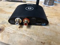
I have an USB DAC (a Topping E30 V.1 actually) that outputs 2 Volt. I have 80 ohm headphones (Beyerdynamics DT770 pro actually).

The adagium of an old Dutch technical oriented audio magazine 'Audio & Techniek' was 'less is more'. More components in an audio circuit will not benefit the sound quality. Food for discussion I am sure but I believe it to a certain extent. So the thought popped in my head why I would need a voltage amplifier stage in a headphone amplifier when the DAC delivers enough voltage? Why not try to make a frontend for the USB DAC to plug the headphones in, a current buffer? I did and it turned out to be a fun experiment using the cheapest components I could find. It is suited for headphones with an impedance of 32 to about 80 ohms.

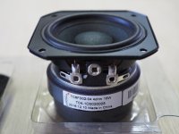
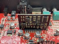
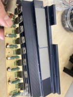
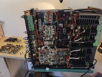
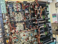
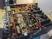
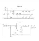
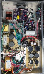
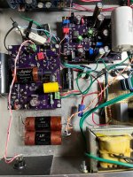
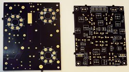
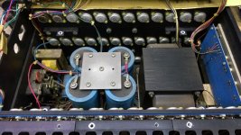
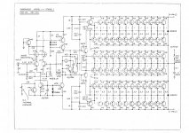
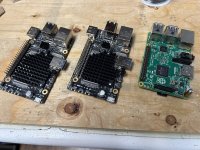
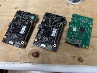
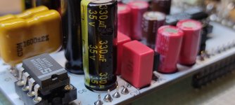
The circuit is a 136 mA biased, class A current buffer that consists of 5 paralleled TO-92 transistors per channel. Perhaps there is some benefit in using paralled transistors, I do not know, you tell me. I have a lot of them, ordered from beyond for a low price.
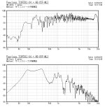
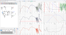
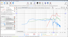
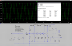
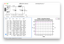
The frequency range runs to 3 Mhz before it begins to drop off. If necessary it can be limited to 80 kHz by using a 15 nF capacitor to ground right after the input capacitor. In my case that was not needed, but see my comment further on.

According to LTSpice it produces nice harmonics, especially the 2nd one stands out. The distortion is not too low, about 0.03% in 32 ohm and 0.01% in 80 ohm, what is to be expected for a simple circuit like this. If it sounds right I will very soon forget that number, the former is what matters to me most.

schematics and THD.png

FFT.png


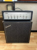
The buffer is named 'Amai-3000' for a reason. 'Amai' is an expression of surprise in Belgium. In this case concerning the sound quality, the temperature, and hopefully it lasts until the year 3000 (well, the enclosure does, could not resist some humour).
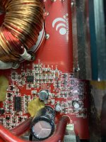
So the transistors and 43 ohm resistors become hot. According to the freely adapted and well known official Nelson Pass Temperature Scale where you place your finger on the component and measure the time how long you can stand the heat without cursing:

Blimey hot: 10 seconds = 45 deg C.
Crikey hot: 5 seconds = 50 deg C.
Bloody hot: 2 seconds = 55 deg C.
Amai hot: < 1 second > 60 deg C.

, the transistors are Bloody hot, but the power dissipation is within range. The 43 ohm resistors are between Amai and Bloody hot but they also should be able to cope.
As a first (endurance) test I left the circuit on for more than 10 hours to see if the cheap components would last; of course they did otherwise you would not be able to read this 🙂 I will see on the long term...

building_it.jpg

board_top.jpg

board_bottom.jpg


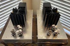
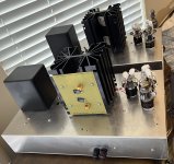
Reading many threads (not only on this forum) and looking at all these expensive oversized fancy pancy amplifiers in the shops you would believe that the bigger the enclosure, the better the sound 
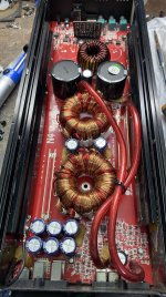
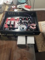
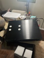
😉 Why not use an enclosure of 5 x 6.5 x 11.5 cm (https://www.gainta.com/en/g111.html) I thought. That may be to the other extreme, using an undersized box like that, but I like puzzles. To let the heat escape and to avoid drilling more holes I lifted the cover of the case a bit by using 4 extra bolts thereby creating an opening around the case.

Btw, before I used WD40 as a lubricant while drilling holes in the aluminium, but a trick that I read elsewhere that I wanted to test is to use hand cream. That worked even better than WD40 and it smells nice too but opinions may vary. There is nothing like the smell of WD40 in the morning, that's why afterwards I treated the aluminium with WD40 to protect it, not to protect it but for the smell.

drilled_holes.jpg

contents.jpg

front.jpg


Oh, and another thing: after finishing it there was a slight hum that varied with the volume. At maximum volume the hum dissappeared. This may very well have to do with oscillation in combination with the power supply, as another post suggested. Replacing the power supply helped to solve that, although I also suspect that limiting the bandwidth by using a 15 nF capacitor to ground right after the input capacitor might as well be a solution.

Maybe the circuit can be improved. I used BJTs instead of FETs because FETs hate me and therefor I hate them and I avoid them like the plague. I had to use 100uF electrolytic capacitors at the input (amai!). However, even considering that and the expectation bias I am aware of, it sounds spacious, natural and especially dynamic. At first I had the tendancy to increase the volume too much but soon learned not to do that not to let my ears fold into my head. Other amps may not sound compressed, but it is my impression this buffer sounds very dynamic. Could that be the result of using transistors in parallel?

To conclude; this very simple circuit might make a base for further experimenting, to leave it as it is or to ignore completely. Thank you for reading this far.

Attachments

  • schematics and THD.png
    schematics and THD.png
    58.1 KB · Views: 101
  • Amai-3000.asc
    Amai-3000.asc
    4.2 KB · Views: 65

Hi, enjoying electronics?

Hi. My name is Jože, going by the nickname Miky. I own a repair shop in Slovenia (Cekim Electronics), servicing all kinds of AV equipment, specializing in micro soldering and also Phone and laptop repair. Started 10 years ago as a hobby and passion. My motto is to get old quality equipment back to working condition and throw away as little as possible. Our world is crazy enough, we have to start thinking a bit differently in terms of mass production and quantity over quality.

In the end: Sharing knowledge is the key to success.

Cheers.
Miky

Cekim Electronics - Logo with Text without background_2.png

Sonic Frontiers and others, PCB fix for Ultra Analog DAC D20400

Direct PCB fix replacement for the Ultra Analog D20400 DAC module installed on many Hi End audio devices.
Based on the excellent Analog Devices chip (AD1862) with an analog sound and great performances!

Audio grade components were used:

Cornell Dubilier silver mica capacitors
Elna Silmic II capacitors
Vishay/Dale resistors
Wima capacitors
Organic Polymer Wurth Capacitors
Panasonic low esr capacitors

The PCB is made with separate Analog and Digital ground planes, all according to the most rigorous rules of dual mono topology, to get the best performance layout.

ATTENTION THE PCB IS SOLD WITHOUT AD1862 CHIP AND WITHOUT OPAMP (which must be single type, such as the ne5534).

The PCB is mounted and rigorously tested.

For international buyers, please ask for shipping quotation before buying.

One PCB is announced here, but other 7 PCB are available on order.

On sale at euro 130 + shipping cost.

PS: If you need, we also offer installation service upon request.

Thanks!

Attachments

  • b.jpg
    b.jpg
    189.9 KB · Views: 1,215
  • c.jpg
    c.jpg
    446.8 KB · Views: 1,065

PASS HPA-1 Clone Board Jeff Young

Jeff Young's HPA1 clone board from JLCPCB. It is 2 oz copper with ENIG.

A partial package including 6 heatsinks, Yageo 1% 1/4w resistors, Vishay 3w resistors, 4 trimmer pots, Alps RK27 100k pot is included.

$80 (includes Priority Mail shipping); PayPal ok. Sold at below my cost. USA sales only as international shipping through USPS is ridiculously high. Please pm if interested.

Attachments

  • IMG_5052.JPG
    IMG_5052.JPG
    336.8 KB · Views: 144
  • IMG_5053.JPG
    IMG_5053.JPG
    280 KB · Views: 145
  • IMG_5433.JPG
    IMG_5433.JPG
    302.2 KB · Views: 131

GZ34 occasional runaway voltage

Hi, I'm just completing my first build, amp based on F2a tube. With much help reading the forums, so thanks.
It's based on Moxtone Siemox online schematic but I've modified to monoblocks that use GZ34 rectified power supplies.
Testing had been going fine, and get B+ around where I expect, surge to 425 then settling around 380. But on a couple of occasions, on one amplifier, turning on from cold, the B+ seems to have continued to surge to 600 or more.
The first time I hit the kill switch after maybe seeing over 1000v, may have been negative (it was all quite quick, I may be mistaken). I added 1n4007 diodes and increased my first resistor to 97ohm from 47 ohm, and even swapped in a nos gz34. Seemed fine for first few times. Then one time I saw the multimeter hit around 600v and stay there. This was a different multimeter and I think its limited to 600v. I tried again later and all was fine.
I have the load wired in with 8ohm load, and valves seems to be drawing 130mA. When it starts up fine I have checked square wave on an oscilloscope and seems good.
Any ideas what may be happening here? Did I just imagine it?
CLC using 45uF first cap. Attached PSUD pic. (Plus bleed resistor 1M not shown).
Thanks for any thoughts.

Attachments

  • GZ34.png
    GZ34.png
    243.3 KB · Views: 89

ALSA and JACKD S/PDIF output

I have some motherboardS with either optical or coaxial spdif output that I would like to use as the only output but all of them have this problem with alsa :
although aplay -l show the spdif subdevice I can not choose it it does not appear in alsamixer or qjackctl devices available.
can someone help me a bit with this alsa simple problem (I can remove jackd if that helps) ?

For Sale UK TubeLab Simple SE amplifier KT88 6L6GC 6P3S-E

TubeLab Simple SE amplifier KT88 6L6GC 6P3S-E

TubeLab Simple SE amplifier that has been stored for the last six years, I need the space.
Didn't think I would ever sell this, my most successful DIY effort.
While I make no claims of safety/ warranty, Always do your own due diligence.
I checked over the amp and re soldered and cleaned some of the connections, then powered up without issue. I spent a night listening, the amp works without any hum or noises.
See photos for condition and moody long exposure glow.
Edcor XPWR059 wired for 240v, currently $179.
Edcor CXSE25-8-5K Output transformers, Currently $154 each,
Hammond 193H choke
Hammond enclosure, with Fender style Jewel LED and power switch.
80uF Motor run cap.
Thermistor for soft start, Auricaps, Nichicon caps.

Comes with one pair of 6P3S-E output valves
One pair of 6l6gc output valves
One 5U3C rectifier
One JJ ECC81 input valve.
£300

Happy to demonstrate.
Collection from Southeast London SE4, not willing to post due to weight and fragile nature.
PXL_20240612_161911697.jpg


Shuguang KT88-98 Matched Pair
Matched pair, never used. In original packaging. With measurement stickers.
£50 including UK postage.
PXL_20240612_152513166.jpg

Attachments

  • PXL_20240612_204424820.jpg
    PXL_20240612_204424820.jpg
    116.4 KB · Views: 69
  • PXL_20240612_161852412.jpg
    PXL_20240612_161852412.jpg
    260 KB · Views: 61
  • PXL_20240612_162109827.jpg
    PXL_20240612_162109827.jpg
    536.3 KB · Views: 68
  • PXL_20240612_154338378.jpg
    PXL_20240612_154338378.jpg
    411.9 KB · Views: 79
  • PXL_20240612_151035662.jpg
    PXL_20240612_151035662.jpg
    436.4 KB · Views: 92
  • PXL_20240612_151038718.jpg
    PXL_20240612_151038718.jpg
    435.5 KB · Views: 92
  • PXL_20240612_151038718.jpg
    PXL_20240612_151038718.jpg
    435.5 KB · Views: 93
  • PXL_20240612_204254149.jpg
    PXL_20240612_204254149.jpg
    155.2 KB · Views: 85
  • PXL_20240612_151332843.jpg
    PXL_20240612_151332843.jpg
    404.9 KB · Views: 75
  • PXL_20240612_163109841.jpg
    PXL_20240612_163109841.jpg
    409.2 KB · Views: 69

Rotel RB985 Noise floor problem?

I recently got a used RB985 on the cheap and trying to make it perform. I have an issue that I have not come across before and am hoping for some ideas or pointers what might be going on.

The odd thing is that the noise changes with what signal cable I use and with the cable disconnected it's "silent".


Adding a pic of how it looks on REW and a Focusrite G3. Red is the signal cable disconnected and green with it connected to the preamp muted and I have obviously tested with other amps, in this case the Rotel RB 980 and with that there is no difference with the cable disconnected or not.

RB985 Noisefloor.jpg

SWTPC Universal Tiger Inconsistencies

I rebuilt a mono UT for analysis in this thread below and found numerous ways to induce
oscillations:
SWTPC Universal Tiger Rebuild For Analysis

I began to make minor changes such as moving grounds around and thought that it
would be good to have another one that could be left without changes as a reference
since I have 3 of the mono block UTs. The second one did not oscillate in any of the
ways that the first one did.
Started by looking for visual differences:
1. First (UTM#1) is on an aluminum chassis, second one is on steel (UTM#2).
2. Capacitor brands are different
3. UTM#2 has a lot of corrosion, probably from sitting in a damp environment
for many years. I should probably clean the grounds.
4. UTM#2 has nearly every solder joint with about twice as much solder as there should be.
a joint could be cold, but who knows?

Obviously semiconductors have wide variations in parameters and I don't have a curve
tracer to test each one. I suppose the VAS is a likely suspect since one with more internal
capacitance might improve stability acting as a Cdom cap.
I know for sure that many of these oscillated from past experience, yet a few builders
report no problems at all.

I wanted to keep the speculation on this issue in another thread just for clarity - so here it is.

I suppose that I should try UTM#3 to get another data point.

Final 0.4 mkIII Electrostatic Issues

Final 0.4 MkIII Electrostatics​

Hi to all.
I recently purchased a pair of these speakers. With the speakers came two different 12v adapters. One was a 0.5va and one was a 1.54va.
Upon listening i found that the 0.5 was not powering the panel ( I did alternate supply to each speaker to confirm it was supply problem and not speaker)
My first port of call was to contact Final where i was informed the 0.5va - 6watts according to Mr Ohms - is enough to power the speakers and that as it wasn't, the problem must be the internal transformer. Now... as the 1.54va seemed to power the panel I thought until I get time to get the speakers looked at and the internal boards tested I would buy another 1.54va supply just so as i could get a good idea of what the speakers sound like. Not able to find a 1.54va I settled for two 2va adapters so at least the supply was matched.
This itself presented another problem as for some reason I cannot seem to hear either panel now!! When i sit back and play some tunes that I'm familiar with everything sounds as it should. The soundstage is huge, the trebles are there and it does sound very good but upon standing in front of the panel I'm not hearing anything!! Am I missing something?
Note: I am using a modded Cyrus 2 + PSX

Current feedback: impedance and phase issue

The difference between current feedback and voltage feedback for audio amplifiers is a non issue. Voltage feedback amplifiers for audio applications are superior to their current feedback peers.

Given a set C of current feedback amplifiers and a set V of voltage feedback amplifiers, there exists an amplifier V(x) that has higher bandwidth than an amplifier C(z)

How much of a phase difference? One or two be junctions or gs junctions. Yes these can make a difference to the stability of an amplifier.

There is an advantage of having a symmetrical design with an LTP and that is LTP error cancellation, especially if the LTP is matched and essentially in the same package. Better still if the LTP package is paralleled.

Current feedback is a term coined from the nature of the low impedance input, nothing more other than the phase and nothing less. Add an active device and it becomes a high impedance input and now we call it voltage feedback
Projects by fanatics, for fanatics
Get answers and advice for everyone wanting to learn the art of audio.
Join the Community
507,611
Members
7,879,556
Messages

Filter

Forum Statistics

Threads
405,838
Messages
7,879,556
Members
507,611
Latest member
mapachesadico