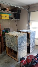
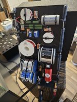
A set of concept subwoofer cabs to trail a few drivers and choose a system for my mini DJ rig which I am calling the VolcanoSS or Volcano Sound System
It should be noted that the low volume cab sizes as drawn are designed for Low Vas/high Xmax drivers/very high power type of drivers such as the DS18 ZXI12.4d and ZR12.4D. The cab concepts will explore if drivers that can usually be heard from a street away can be ported to domestic and live use. This cab volume is easily increased for use with regular drivers
Build is using any stiff machinable material or combination off. Walls are designed to use 'thickness for stiffness' and at minimum MDF for pro or XPS for domestic duty and PVC foam for super heavy duty. MDF can be painted or veneered, but best performance and durability results are with an FRP sandwich. This will remove any remaining flex in the MDF appropriate to super sub duty
Driver location keeps the roll surrounds out of the main air volume, and the air cupped by the cone will add to the main air volume. A FreeCAD macro is used to determine the exact box material volume and then cavities are created, and the macro shows the new material volume. The difference of the two is the chamber air volume. The model takes the air volume within the driver cutout area and loss due to braces into account using this process
A small desktop CNC is required to build up the former in areas thicker than the panels and the tricky bits, but the cab can also be done using kerfing and knowing use of hand tools
The design can be reproduced in any manner or for any purpose. There is no IP concerns but keeping the VolcanoSS name is desired. This is just a design concept and can change
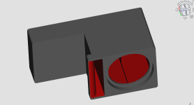
Volcano TLS
First up is the Volcano TLS, a sealed design concept targeting heat management. The driver is fitted reversed so that the motor assembly is in free air. It can be configured for any driver size, and cab volume is adjusted by changing the height of the upper and lower secondary air volumes. Both secondary volumes aren't required to be used at the same time or at all
The upper and lower chambers can also be closed off to use as an electronics bay. Or another chamber slice can be added to the cab for such use. A cavity or pod attachment can be done to the rear panel for terminals or electronics
The large blank face can take a fabric print sock or Plexiglass window. Mesh from a very large strainer can be modified to fit over the back of the driver. A rim for the mesh can be machined or printed. Alternatively, a fabric sock can be fitted over the whole speaker and recommended easy method
A second unit can be built on the other side of the face for a dual opposed setup
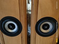
As drawn, the model is for a DS18 ZXI12.4D vs DS18 ZR12.4D trials, but the model can be adjusted to any driver and internal volume
Model specs (variable)
Internal air volume 19L
Width 360mm, height 540mm, depth 332mm
Wall thickness 32mm


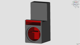
 Volcano Kiss
Another sealed design concept with heat management for a conventionally mounted driver. The long side panels are 3mm alloy plate to couple internal air to the room for heat dissipation. An alloy heat collector shrouds the magnet and couples to the internal 3mm alloy plate rib. This plate is spaced out from the back panel using battens
The back of the magnet also couples to this plate for heat transfer as well. The plate has a hole that the pole vent fires through and, with the battens acting as standoffs, couples back into the cab air volume. A lock can be added to the top surface of the shroud to secure the magnet if desired
This alloy rib runs across the cab and couples with the alloy side walls. Why alloy side walls?
This is a fairly flat cab, two can be brought together for dual opposed. The back is deliberately kept clean to allow this
As drawn, the model is specifically tailored for a DS18 ZXI12.4D, but the model can be adjusted to any driver and internal volume. Volume is changed by changing height
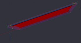
The third pic is only the alloy structure. Let's call it a 'TF radiator'. Last pic shows dual opposed
Model specs (variable)
Internal air volume 24L (driver is 4L)
Width 360mm, height 450mm, depth 248mm
Brown = wood, red = internal wood, grey = alloy


 Volcano TLAmp1 and TLAmp2
Will be building this one to break the driver in and test the small Sd proof of concept thingy for the pro mobile subs. This folds such to fit in the car but also, if it works well, will form the basis for the potent instrument amp. Preferred over the BR due to managing the pipe resonances better, tuning the pipes in HR as a TL. Full story here
https://www.diyaudio.com/community/...fer-cabs-design-and-build.415232/post-7745529


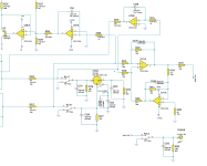
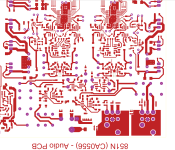
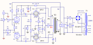
 , i've registered a couple of years ago and been reading along here but never really posted anything. Now that i'm finally having a bit of a diy audio project i'd like to discuss some things here with people that are a bit more experienced in the audio field. I've done electrical engineering so i'm a bit familiar with general (micro) electronics, but audio is a whole thing on it's own.
  Have a good day and enjoy your music!