Following in the footsteps of the
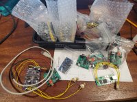
Aksa Lender preamp, Hugh and I have been working on a Class A power amp that uses the Aksa Lender front end. We wanted a SE Class A amp with more efficiency than a simple CCS so we decided to try using the very nice Pass Aleph (dynamic bias) CCS. Hugh is using a P-MOSFET as the lower output device, so this is sort of a hybrid, modified Aleph. It is a very simple 6 active amp with no fancy unobtanium JFETs, SITs, hockey pucks, power JFETs, fairy dust Sony FETs, or signal transformers. If you look at the prototype built on veroboard, you will see the usual low cost stuff. The fanciest part I have is a 10uF Silmic II input cap. The rest of the caps are budget Aliexpress. I like to proto with cheap parts, that way there is less pressure in case it flops
🙂 I am using genuine Vishay IRFP's from Mouser though.
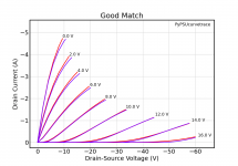
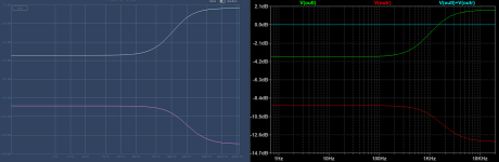
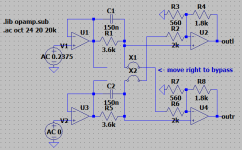
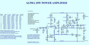
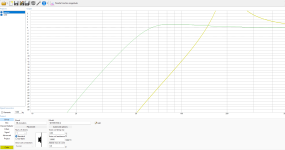
Here is the basic circuit and predicted performance specs (it's good for about 20w with 24v rails):
The circuit uses Hugh's Aksa Lender preamp front end with an Aleph CCS on the top, and a P-channel MOSFET on the bottom driven directly from the Aksa Lender LTP. No CCS on the LTP needed.
Hugh also worked on a monster version of this amp with +/-35v rails and 150w of dissipation per channel to make 53wrms into 8ohm before clipping. To get things rolling, I opted for the +/-24v rail version at a more modest bias of 1.2amps. Slowly work my way up in bias current and then maybe rail voltage (with bigger output devices).
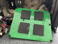
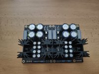
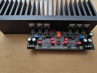
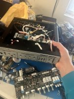
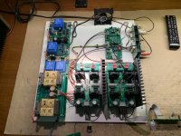
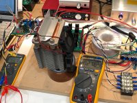
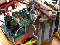
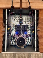
So here is the prototype on a tiny 5cm x 7cm veroboard with two MOSFETs hanging off one end right next to each other. Why so close together? I wanted to use a computer CPU heatsink with heatpipes to cool them - in anticipation of 140w later on. This amp was particularly difficult for me to get running because I made so many wiring errors (a problem when you build it in the wee hours of the morning after a full day of work). Once I found all my errors, the amp fired up no problem. I matched the beta's of the input LTP KSA992's and got perfect 0mV DC offset with no trimpot. You will notice that the tiny (relatively speaking for a Class A) hetsink is fan cooled and has lots of heat pipes (which normally work flipped the other way unless they have capillary wicking inside). But I found them quite effective upside down even as temp was 31C with 55w dissipation. These are salvaged Dell heatsinks for workstation, about $12 to $15. For the record, I am using 1000uF 35v on C3, 22pF NP0 on C4 and C9, and 4x2.2nF (8.8nF) MKT film on C7, 0.47R on R17 and 0.15R on R18. I also have an input RFI filter consisting of 2k2 in series before C1 and a 220pF MKT cap to GND, and 100uF 63v on C2. On C5 and C6 I am using 220uF 100v caps. i had a nice 220uF Silmic II but it was too big to keep on the board and still let me see the resistors unerneath when I was debugging. Otherwise, parts are used as shown on schematic.

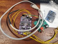
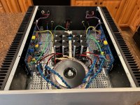
Closeup of the amp:
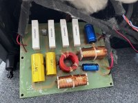
Without heatsinks (I eventually removed the Silmic II 220uF 50v Aleph feedback cap to make room for debugging):
Listened to it for a few tracks and must say, it sounds quite nice and engaging. I know the sound. Foot tapping good - typical Hugh Dean style amp.
😀
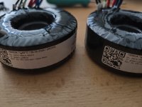
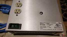
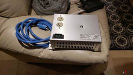
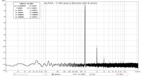
So here is the first measurement of this simple unassuming amp that takes the best of all worlds. 1kHz 2.83vrms into 8ohms and we get 0.027%THD but in typical Aksa style, mostly in second harmonic, and 10x less in third harmonic, and not much else. This is running well below the recommended 2.0amp bias. So I expect the THD to drop. But the noise floor looks great - actually very good for a linear PSU - perhaps the best I have I seen for one of my linear PSU amps. I am using a basic 100VA donut with 18VAC and a Project16/Prasi CRC PSU with 22mF caps all around and 0.235R on the CRC.
I will try boosting the bias current next, and then maybe try to go for the monster 53wrms amp with 35v rails
🙂
Hope you enjoy it - and if enough interest, JPS64 can design a splendid PCB for us to use. Thanks to Hugh for another gem to the DIYA community. And thank you to Mr Pass for the wonderful Aleph CCS.
Here is the latest Schematic for the Big Boy 52W version - now at a little under 3amps bias and 90W dissipation per side, still need two CPU coolers per channel.
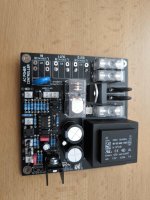
Edit Feb 11, 2018: the Alpha 20 PCB is finally built and tested.
It measures very well here with 1.31amps bias and produces 0.0069%THD for 2.86vrms into 8ohms:
ALPHA 20W schematics and stuffing guide for v4 (production boards) here:
Aksa Lender P-mos Hybrid Aleph (ALPHA) Amplifier - Page 12 - diyAudio
Edit Feb 20, 2018:
BOM v1 for ALPHA 20W PCB layout v4 (above schematic) here:
Aksa Lender P-mos Hybrid Aleph (ALPHA) Amplifier - Page 51 - diyAudio
Edit Mar 5, 2018: premium components build ALPHA20:
It does indeed eek out a bit lower distortion with Vishay Dale resistors and all Wima and Silmic caps, now about under 0.006%THD for 2.75vrms into 8ohms:
Edit March 25, 2018 - Alpha 20 for 4ohm loads version:
Aksa Lender P-mos Hybrid Aleph (ALPHA) Amplifier - Page 124 - diyAudio
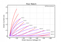
Ignore the triple outputs - purely used to simulate a single larger 500W capable IXYS MOSFET pair which will not need to be matched. Hugh does not recommend using triple output IRFP’s
Edit April 4, 2018: BigBoy is alive and singing! The Beta build went together almost perfectly. Only one minor circuit error on the grounding of the LTP smoothing cap (fixed with a jumper). Amp starts up uneventfully and without any adjustment to achieve 3.0amps bias current and 1mV DC offset.
Here is 34wrms into 8ohms from +/-27.6v rails:
Here is FFT at 2.84vrms into 8ohms:
Edit April 4, 2018 - here is the updated as-built schematic for Alpha 20 with 1.35amp bias and no turn-on thump feature. Note that if all pots are removed the amp is a simple adjustment-free Class A amp with DC coupled output that has DC offset within 10mV (typical) and self-tracking, bias current is auto-regulated and very stable:
Edit April 7, 2018: Alpha B.B. in stereo!
FFT of Alpha BB at 2.85vrms into 8ohms
Edit April 10, 2018: Summary of various settings to change amplifier configuration bias setpoinysnand speaker impedance driving capabilities. Courtesy of Danny_66:
Aksa Lender P-mos Hybrid Aleph (ALPHA) Amplifier - Page 166 - diyAudio
Edit April 13, 2018: Simulation LTSpice files of Alpha 20 4R and 8R by Danny_66 here:
http://www.diyaudio.com/forums/soli...id-aleph-alpha-amplifier-172.html#post5404051
Edit April 19, 2018: 10kHz 17vpp square wave into 8ohms on Alpha BB:
Edit Aug 23, 2018: several people have contacted me about ramping up for a new build. So here is a recap of suggested schematic for a 4ohm Alpha 20 (which probably puts out closer to 35w into 4ohms):
Edit Sept 4, 2018:
Tips for 4R capable circuit...
Aksa Lender P-mos Hybrid Aleph (ALPHA) Amplifier
Edit June 11, 2019:
revised table of source resistors for setting bias current in Alpha 20 for 8ohms and 4ohms by Danny66:
Aksa Lender P-mos Hybrid Aleph (ALPHA) Amplifier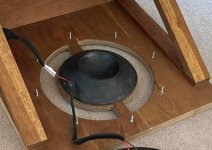


 , I use a lot of subjective terms/descriptions of what I hear. One of those is "transparency" and I wonder if this is in fact a low noise floor?