Mod SB26ADC for Lower Fs?

Over the years, I've dissected a handful of mostly blown tweeters. The ones with lower Fs are all equipped with a rear chamber. Basically the center portion of the magnet structure inside the voice coil/slot is a hollow tube that goes right through the magnet structure. The backside is closed by a (usually) plastic cap which enlarges the air chamber and seals it behind the dome. Sometimes, these spaces are filled with damping -- poly fiber, foam, etc. -- which appears to lower the amplitude and Fs, if only a touch.

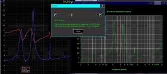
The SB Acoustics SB26ADC is a current DIYAUDIO darling for its good performance & modest price. Equipped with a small rear chamber, my sample of this tweeter has a Fs of 590 Hz with a peak of just 6 ohms ( double the 3 ohm norm). Xmax is rated for1.2mm (p-p), high in comparison to most other tweeters, even larger ones. The Wavecor TW030WA11, for example, a 30mm dome with Fs of 440 Hz, is rated for Xmax 0.4mm (0.8mm p-p).

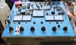
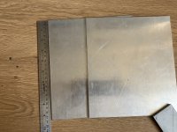
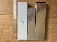
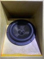
Here are pics of a disassembled SB26ADC.

PXL_20231221_003616553.jpg

Unlike the 29mm series, the 26mm dome/coil appears to be user-replaceable. Clearly visible in the magnet structure is the copper ring inside the slot for the VC/former, the hollow within, and a cone on the inside of the plastic back cover. That cone is probably to reduce standing waves between the dome & the back. No damping material.

PXL_20231221_003656858.jpg

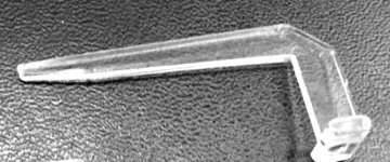
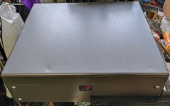
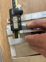
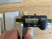
This pic shows the back cover; the total depth of the air space behind it might be 4-5mm.

It seems pretty obvious that if the total rear chamber space was enlarged, Fs would drop. Would this allow operation to a lower frequency, especially with a 6" Augerpro waveguide?

I'm want to cross as low as 1200 Hz. The high Xmax of the SB26 might make this safe enough? Or at least 1500 Hz.

The main benefits for me are... better power response in 2-way xover with 8" (or even bigger) woofer, improved dispersion/power to higher frequencies. Plus all the positives we already know about the SB26.

The mod itself looks like it should not be difficult: Pry the plastic back cover off and replace it with a half ( or smaller) portion of a hard plastic ball of suitable size. Fill it with poly or wool fibers to control resonances. I'm tempted try but would prefer not to destroy the back cover.

Thoughts anyone?

Trimmers

Do we have more than 25 turns trimmers ?
What is the resolution, one can really expect with those tiny screw 25 turns ? I would say 1/8 turn
Are they all the same among popular brands ? In other word is there a best about accuracy setting and stability.
My problem: A +/- 2mV offset that I wish to trim at 1uV accuracy.

Ian Canada Upgrade Kit for Denafrips ARES 12th/II

Hi everyone,

I purchased the upgrade kit from Ian Canada for my Ares II. I'm now thinking that it is not for the 12th edition OR the ARES II, but only for the 12th edition.

Bottom Left - The unmodded clocks on my ARES II
Bottom Right - The wiring for the upgraded clocks on the guide for the 12th edition upgrade on Ian Canada website

1724536606154.png
1724536730348.png


the PCB elements numbered 103 are likely C29 (GND) and C30 (GND), but I do not see what I would use for C121 (GND 3.3V) anywhere.

Is there any salvaging this? Do I just sell my Ares II and try and find a used 12th edition? Would likely cost about $250 to upgrade it on the used market, which I would prefer not to do right now.

Is there even such a thing as ARES 12th-2? I see 12th-1, but cannot see a 12th-2?

Thanks so much,

A pic of my whole ARES II in case it helps.
1724537041803.png

Understanding acoustic offsets vs. group delay with LR4

Hi everyone,

I'm hoping I can ask you to help me with something I've really struggled with. I've built a number of passive speakers and I think I understand the concepts of acoustics offsets and the phase relationships of LP and HP drivers and the need to account for acoustic offsets. I recently built a 3 way speaker with LR4 filters and while I was able to finish it successfully it also pointed out a huge gap in my understanding. The relationship between the physical acoustic offsets of a driver and group delay. Let me see if I can express this in a very practical way.

Consider this design with idealized drivers and zero acoustic offsets:

1723398716690.png


Simple LR4 HP/LP, sums to 1 and the phase wraps around at 1 kHz like it should. So, new to me is the all pass behavior. Below 1 kHz the LP filter now has a group delay ~ 4 mSeconds.

1723398792077.png


Ok, this part I can accept. It's the very next part where I prove how little I understand. In a "real" 2-way the woofer could be 1" or more behind (lag) the tweeter. Using DSP, this is a simple problem of tweeter delay. So my question is, how much does the GD of this LR4 filter affect my choices? In reality I ended up getting to an ideal delay by examining the null with an inverted driver, but I'm asking in theory here. What's the net effect to my delay, and why? It seems based on empirical practice that I needed much less delay than expected, and i don't now why.


Thanks for theorizing with me and helping me overcome this big mental wall I"m hitting.

Listening to a transistor's distortion

Lurker/newb here, I just had an idea: a setup which would allow you to listen to the distortion characteristic of a particular transistor.

Recently I've been reading about basic source-follower setups (i.e. headphone buffers), and how you can use two out-of-phase followers to get rid of the output capacitor (directly couple to the speaker/headphone).

Of course, if you don't have balanced input, you can use the setup in "single-ended input mode", i.e. ground one of the inputs. One of your outputs carries the signal and the other is constant.

Well, taking this a step further, if you fed both followers the same in-phase input, your speaker/headphone sees the same signal on both ends, no current flows, and no sound is produced. You can adjust the input pot all you want, it won't make any difference.

But what if we adjusted the input pots unevenly? Both followers would produce an in-phase signal, but of different amplitudes, so the speaker/headphones would see a reduced volume output.

By carefully adjusting the pots, you could increase the output signal produced by each follower while maintaining a constant volume as seen by the speaker/headphone. In this way, you could "turn up the distortion" while keeping the output volume the same.

Using this technique, you could swap out several different transistors / fets and compare what their distortion characteristic sounds like. Or you could try different bias current settings and compare what the distortion sounds like.

Perhaps an old idea, but news to me! 😀 I've never really had the opportunity to compare what different types of distortion sound like, so this idea is appealing.

Hello from the beach

Hello everyone!

I’m a young manager with a passion for all things audio, and I’m thrilled to join this forum. I run a cozy little beach bar where the sound of the waves meets great music. Being a charismatic person who loves the summer vibes, I thrive on creating the perfect beach atmosphere. Music is a huge part of what makes my bar special—I focus on finding the best tunes that fit the sunny, laid-back environment. From chilled-out beach beats to lively summer anthems, I’m always on the lookout for tracks that enhance the seaside experience.

When I’m not at the bar, you can find me exploring new music genres or diving into audio equipment reviews. I’m excited to connect with fellow audio enthusiasts here and share ideas about creating the ultimate sound experience. Cheers to great music and sunny days!
  • Like
Reactions: geoturbo

Selecting volume pot for specific output impedance

I have a tube preamplifier with an output impedance of 1.6K and I'm trying to select the correct volume potentiometer for the power amplifier to match to this. Am I correct that the general rule is 10:1, which would put the volume pot around 16k? Assuming this is the case, would 20k pot be a good choice, or would it be better to be up around 50k to be safe?

Amp/voltage rating for switches for Simple SE?

Anyone know what the optimal amperage and voltage ratings are for the Rectifier SPST switch and the Feedback/MODE DPDT switches are for the SSE? I've found a few mentions on the board of specific switches that work, specifically nothing that states that the ideal specs are for new switches.

I have some switches that are 3A 250 VAC (SPST) and 2A 250 VAC (DPDT) and I'm wondering if these will work. I'm in the UK, so 230V mains, but not sure if this matters here.

Thanks!

DSP software for Apple Mac with D/A DAC8 PRO or MOTU UltraLite Mk5?

I'm looking for a more conclusive and proven approach of using an Apple Mac as crossover and DSP. There seems to be no industry-proven approach and the field is quite experimental, e.g. no established vendor offering this. What's the problem? I understood so far that software like CamillaDSP or Blue Cat’s MB-7 Mixer and hardware like dac8 PRO or MOTU UltraLite mk5 would be a good foundation. Would anyone share their experience especially in demanding studio, live and PA setups?

Background: We needed a sound system for festivals (100+ people) and I found very cheap 2 x JBL ASB6125 (32Hz-1kHz) and 2 x JBL 2450H (500Hz-20kHz) and 2 x QSC amps. For this I got excellent feedback on diyaudio: How best setup multiway PA system. But I'm struggling when it comes to the best active crossover config. First I wanted to do it all analog. I tried an old Ashley crossover but that had too much noise. I could get a BSS FDS-360 which was top-notch quarter century ago. I preferred analog because it's just plug and play and I'm not a fan of multiple A/D, D/A, A/D conversions. Then got a DBX Driverack PA2 and was impressed by its ease-of-use and audible improvements (compared to the old Ashley). But then it's only half-way digital compared to the t.racks FIR DSP 408 at almost same price. But that thing doesn't have Mac software so that led me down the Mac-as-DSP path. Here I got excellent feedback re What else than an Apple Mac Pro M3 do I need to replace DBX Driverack PA2? But I'm not sure if the suggestions (e.g. dac8 PRO, CamillaDSP) are targeted for home cinema/hifi or demanding studio, live and PA setups, which must be sturdy, reliable, idiot-proof. There is excellent info on CamillaDSP - Cross-platform IIR and FIR engine for crossovers, room correction etc. I will definitely try this out!

Compare these kits, explain the differences?

What about the more expensive kit makes it better than the other one? What might make it worth the price?

I recently got into a sales gig that pays very well, so this is not a purely academic question. In the near future I could build the $10k kit, if I had a good enough reason to do so.

https://www.madisoundspeakerstore.c...peak-ellipticor-a50-3.5-way-speaker-kit-pair/

https://www.madisoundspeakerstore.c...o-sb12.3-sb-acoustics-12-dual-midrange-3-way/

Stepped Baffles

On a lot of TG speaker designs there are stepped baffles with the HF unit set back 20mm.
I spoke to another speaker designer recently and he said that from 2 /3 metres distance he would doubt that you could actually hear a difference from using a stepped or flat baffle with the same crossover.
My question of course is what do you think.

For Sale (EU) genuine Toshiba 2sk170 BL - matched pairs, quads and octets - 6mA to 10mA Idss

For Sale: some matched 2sk170. I sourced the parts at the last known reliable source for genuine Toshiba 2sk170s - millenial media aka ebay seller punkydawgs. This source is also recommended by Nelson Pass.

I matched the jfets with the help of a simple matching jig and a spreadsheet. Take a look at the pictures attached to see what is left.

machted octet: €65,-
machted quad: €30,-
matched pair: € 15,-


Shipping (second class tracked small parcel):
EU - €9,-
UK - €12,-
US - €16,-
other countries: please ask


Please also take note of my other items: search for "For Sale" and restrict results to Member "AddiDub"

Edit 8-2024: adjusted pricing to make pairs and quads more attractive

Attachments

  • s-l1600.jpg
    s-l1600.jpg
    126.9 KB · Views: 186
  • matching-jig.png
    matching-jig.png
    35.6 KB · Views: 201

What is this tube?

I have a couple of 1943 Amperex JAN-CEP-120 tubes, NOS in boxes.
It looks like a smaller version of a 211(vt-4c) or 845, the only reference I can find about them is a pair for sale on a chinese website last year.

Does anyone know what they are and/or have any specs?

An externally hosted image should be here but it was not working when we last tested it.


The picture attatched shows an amperex 211, the cep-120 in the middle and an 845 on the right for scale.

If suitable, they would make a cute SE amp, but replacements could be scarce.

Regards,
Dave.

A60-V1.0 vs. A60-V1.1?

Hi, credit to all the work that people have done on the A60 power amp "clones". I do have several questions:
1. Does anyone know the difference between the A60-V1.0 and the A60-V1.1 boards?
Note: A60 using 3x NPN and 3x PNP output stage version, not the 8x NPN and 8X PNP high power version.
I have looked high and low for this info and have had no luck to date.
2. Has anyone experimented with a revised VAS stage?
The A60 clone boards use an oddly revised cascode with bootstrap VAS stage vs. the Accuphase simple but effective cascode Darlington version.
3. Is there any good data on the THD vs. Po and frequency behavior of the A60 or the A60+ power amps?
4. Is there any concise discussion of mods or improvements to these boards?
Thank you, and regards.

I2S / RJ45 advice

I have an I2S break out box which will allow me to get I2S from my streamer (hp mini) via USB and cd player (via spdif coax).

And its outputs are aes toslink and RJ45.

And so what I want to do is try buying one of these cheap ESS chip dac modules with obviously I2S pins (a block of 5) at one end and left and right RCAs at the other.

So I'm looking at either getting or making an ethernet break out cable.
But the standard ethernet cable has 8 wires? (and I've found a 1 ft RJ45 break out cable that has an 8 block at the other end.

But the dac module I'm looking at has a block of 5 pins or sockets on it.

I saw on the soekris thread a plan that has the 8 pin layout with the first 3 being ground but being 8 that doesn't suit either.?

Alternatively is there an I2S package I could buy with the dac module and cables together.?

Thanks in advance.

Threshold SA/12e mechanical hum from transformers

Good day all, in the last few months I have upgraded from my Threshold SA-2s to an un-updated pair of SA/12es. Love the big Thresholds as the drive my Kappa 9's as they are supposed to be!

Anyway the 12's have an audible mechanic hum from the transformers. I am supposing that it's due to the age of the PS Caps at 30+ years. It's remarkable these days how difficult it is to find CDE capacitors but I have managed to source the 16 quite reasonably priced and in stock! Very nice.

I am going from the original rating of 27,000uF/85v to a 41,000uF/75v cap as I did also with the SA-2s. (The 2's I actually stuffed 4 per chassis to quite an audible difference.) Figuring that should work just fine.

My question for you fine folk is, I figure I should change the rectifiers as well, 2 per chassis 35A is the original, and should this be increased or just going to a fast IXYS at 35A be sufficient? Also is there somewhere else I should look to update that might be impacting the transformers cause the technical hum?

Thank you in advance!

Scott
  • Like
Reactions: andynor

Opinions on SET transformers for 307a amp

Planning to build an SET 307a tube amp. Looking for opinions for best output transformers -- some candidates I am considering. Please provide feedback and recommendations on reasonable, high quality candidates:

Hashimoto HC-507U
Lundahl LL1623
Silk
Magnequest

Have not used any of these but wish I had the chance to compare the nice ones.

thanks.

Easy Creek 5350se tweak

I've been enjoying my 2002 dated 5350SE amp, especially using DIY TNT AirCoil Interconnects. The detail and clarity have been very good and the interconnects measured 1.5uH, 31.3pF and 0.034 ohms for 1m and cost £24.

However, the RCA input/volume control (passive pre)/power amp path of the 5350SE is quite long, has more L, C and R than ideal and I don't need more than one input, nor the extra facilities (phono pre etc).

I wondered if I could apply some of the interconnect principles to the RCA input/volume control/power amp path of the 5350SE without butchering any components.

YES! (Please see attached photo)

IMG_5350se bypass.JPG


I installed a boxed header socket on the remote/volume board to facilitate A/B comparison and to easily restore original functionality, if desired.

Even with unshielded twisted pairs from some Cat5e cable the clarity, transparency and detail exceeded my 4330Mk2 - I could easily hear subtle details and quiet lyrics, individual instruments were better resolved.

I've now used Teflon insulated 23 AWG 6N silver-plated solid core Ohno Continuous Cast copper wire with 96.5% tin/3.5% silver solder.

WOW!

The clarity, transparency, detail, focus/coherence and bass authority are superb!

All for £10!

I've not yet measured/analysed how frequency response or channel separation have been affected, but I'm loving it!

Introduction - Bart

Hi, I've wanted to build my own speakers for a long time and finally did it: the frugel horns mk3 🙂
I've recently finished an education in electrical engineering and it's a bit ironic that I choose this design because -electrically at least- the concept is kept simple: there are no crossovers. But I've enjoyed the woodworking and I'm pleased with the sound of the almost finished mk3's!

Suggested bias current for IRF9630 and IRF632

Hey all, I am checking up on an amp that is getting warmer on one channel than the other. This amplifier doesn’t make it super easy to check his current. I took out the positive busbar and installed leads so that I could measure the current.

IMG_1802.jpeg


For the warm channel I’m measuring about 30 mA per device and the cooler just a little under 10-1/2 mA per device.

For amplifiers using lateral MOSFETs in TO3 cases it seems the general rule is to shoot for 100-110 mA per device. At least for the Hafler stuff. For my B&K amp that uses TO3p it’s about 50 mA per device.

What would be suggested for these smaller TO220s?

Dan

uTracer6, ExtractModel and getting obscure error "*** Internal error in DetSweep"

Having used a uTracer3+ and ExtractModel for years to create spice models now I am trying to create spice models with a uTracer6 as the 6P36S can support very high plate currents that I want to model in spice.

I am using the ExtractModel software from DOS4EVER that I have successfully used for years with my uTracer3+.
Now with the 6P36S tube data collected with a uTracer6 I get the error in the title, "*** Internal error in DetSweep".
I have so far failed to find the cause.

Does anyone have a list of error codes for ExtractModel that may provide a hint as to what it is not liking in my data?

Has anyone see this error before?

I attached the data files I am using.

Attachments

Outlook saga

My current email addresses were hacked and blocked so I moved over to Microsoft outlook.
Things were easy enough, just create new email addresses then change them in my ebay, RS Components etc.

Then I got a message saying my main email had been blocked due to misuse.
I was just sending normal emails I didnt do anything wrong.
I tried to get it unblocked but went around in cicles as unblocking URL kept asking for phone number but after I input it it said there was a problem with that verification method and to try another verification method.
But there wasnt one !

I got in touch with Microsoft and a day later they sent a URL to reset password and account.
I tried it and kept getting too many tries message !

So just going around in circles at the moment.

I looked up outlook email blocking and it appears you can only send a few emails a day before becoming blocked.
It suggested upgrading account to Microsoft 365 and trying again.
So the free outlook wasnt so free after all.
Must have spent a full day trying to sort it all out.
  • Like
Reactions: indianajo

Convert Biquad coefficient list, into a string?

Hi all, need help finding easiest way to do a conversion task.
I need to convert a txt report that lists biquads like this:
1724168921388.jpeg


into a string like this, and also add an a0 value of 1 as highlighted in orange: (note a0 is not listed above)
1724169001563.jpeg


If I only had a few to do, manual is easy. But I need to do 20 at a time, and try a number of sets.
A single csv file with 20 lines, each line a biquad string like above, each string pulled from the original txt report and converted, is what I need to get to.

I don't know where to start...whether this is a simple enough task for an advanced txt editor, or move to Excel/spreadsheet, or move to Excel with an AI spreadsheet assistant.

Happy to do the work/learn...just would like to get a vision for easiest route. Been a long time since I've done any type programming...
Thx for any guidance

Amplifier speaker relay driven way too hard... Fine anyway?

Hello!

Probing around in my vintage amp I noticed the voltage present on the speaker relay coil was about 39 VDC, way higher than its rated 24V. The relay is a Potter & Brumfield RTE24024F, 1440 ohms/400mW coil. Below is the relevant part of the schematic; sorry for the bad scan quality this is the only one I could find online.

Capture d’écran 2024-08-24 195448.png


The relay is fed from the left channel output stage's negative rail which is -42 VDC unregulated. 680 ohms series resistor R3 drops some volts to bring that down close to 24V. I went ahead and simulated the circuit and in this configuration the relay would see 27 VDC.

In my amp this resistor is only 220 ohms and the relay coil then dissipates about twice its rated power. All the other components are operating correctly.

I only have the schematics for the rev. 3 revision of the circuit whereas my amp is rev. 1. The original relay failed about 20 years ago and I had it replaced by an authorized dealer - perhaps the original circuit really had 220R or the repair technician changed it.

At any rate this amp has been running 24/7 for like 15 years without problems... Do relays typically can handle this kind of abuse or I was just lucky on this one?

In a few weeks/months I'll need to replace some old caps and was planning to preemptively replace the relay with a fresh one, to be sure to have less oxydised contacts. It's already 20 years old after all. I'm thinking of replacing the series resistor at the same time with a 680 ohms like specified in the rev. 3 schematic.

Is that a good idea or a case of "If it ain't broke don't fix it" ?

Thanks in advance.

Philips AD 9710 M 01 SD?

Hello dear audio friends,

who here has an idea how big the relevant membrane area SD in qcm/square inch is exactly on a vintage Philips AD 9710 M 01. I can measure or calculate a circle area myself, that is kindergarten. 8 inch fullrangespeakers are usually around the 220 sqcm SD – if a multiple is needed it does not help to estimate, the error is then bigger. There must be somewhere reliable facts about the SD on the AD 9710 M 01!?

Already best thanks for your infos!

Kind regards Gerd

Battery Life Saver

I purchased the "Battery Life Saver" perhaps more than a decade ago, off ebay from the OEM as a "cosmetic second". I dare say it works. having brought back its money's worth of lead acid batteries from going completely useless. Last night, I connected it (along with the "brick" charger) to my 24V lawnmower whose batteries are losing capacity - and went to bed. During the night, it burned emitting magic smoke and oozing a quite noxous brown oil that I cant quite get the smell off my hands (see pic). A potentially more dangerous situation than smelling up things out in the garage and my person.

I called the place which is still in business and offered to send it back for FA. They offered 10% off of a new unit, which is ~$100+. There was no reason for it to fail, as it's rated for use up to 36V. It's potted as I assume they dont want you to discover "how it works" easily.

I'm not sure I want to buy another unit. I'm an engineer, I have a function generator and I know how to drive a FET to sink current pulses. The OEM touts "Square Wave Technology" - I know what a square wave is. When it was working, I never bothered to assess the frequency, the duty cycle, not the current amplitude of whatever it does when you connect it to a battery.

So my question to the anyone here is, if I wanted to replicate this thing using my function generator along with a FET and a couple resistors, what would be the FG setup for frequency and duty cycle, also the current pulse amplitude? Just wondering if anyone knows offhand. Thanks!

IMG_3154.JPG
IMG_3154.JPG

Hello... again :D

Hello diyaudio folks. I am actually returning from a long time ago. E-mail address shanagins.. etc. None the less. I have jumped back in with just enough knowledge to get myself into trouble and am looking forward to chatting with you all about fixing the horrors I create.
My main interests are converting old tube radios into guitar amplifiers. So far the outcomes have been satisfactory. Years have passed though, and my knowledge and patience has grown. Mostly the patience.

45 SET amp Project

I am working on a new 45/45B tube SET AMP project for 2023.​


1. output tube 45/2A3.. interchangable​

2. output transfomer PT and Choke -->Hashimoto​

3. output power 2W 45 tube​

4. Tube set 45 + 12AU7X 2 + 6CA4 / EZ81 X 2​


I need 30 -35 participants to start this project..I am excited to hear the magic of 45 tube SET amp.

I need your valuable feedbacks too.

We are planning to offer one version

premiun version (with Hashimoto H20-7U + Hashimoto Chokes X 2 + Hashimoto PT )


Full Music Balloon Mesh Plate - Gold Pin


Full Music Balloon Carbon - Gold pin


WTB Marantz Dial Pointer needed

Looking for a Marantz Dial Pointer.
I'm currently restoring a first generation Marantz 2215.
Btw.: If anyone has an idea where I can find the fuse board that my receiver has mounted next to the power amp (https://www.diyaudio.com/community/threads/oldest-amp-you-still-use.388499/post-7543721) in the circuit diagram, I would be happy to hear from you.
Thanks in advance!

Attachments

  • Marantz Dial Pointer.jpg
    Marantz Dial Pointer.jpg
    101.3 KB · Views: 53

tweaking classic Linn LK1 & LK2 / LK280

Hello Folks !!


I'm doing the next couple of tweaks to my old Linn LK1 preamp
and the LK2 poweramps right now.

Some years ago I several caps in the RIAA section, most ps and
decoupling capacitors.

Parts used are Wima FKP3, Elna silmic, cerafine, BC 051 etc..

Now I will try Epcos Sikorel an Mundorf M-Lytic HC for the power amp
(ps is separate).

Biggest problem:

Coupling caps in the signal path even in the MC preamp are several tantal caps of small size.
Most of them are 100 + 22 µF parallel.

How to replace them? BG, Oscon, silmic ??
There's no space for FKPs.. :bawling: :bawling: :bawling: :bawling:

Another question: Does anybody have more information about tweaking old Linn gear ??

ALFET MOSFET give away (ALF08P16V + ALF08N16V / 2 pairs)

I put some stuff on sale on Swap Meet, but forgot to say anything about these. So I guess it was meant to be that, following Codyt's example, I'll give these to someone here on the Pass Labs forum. This forum has been a huge aid and inspiration on my Audiophile journey. Also the kindness and willingness to help even us "not so into the knowledge", is beautiful. So it is only fitting to give something back. So here is a chance to get MOSFETs for the F7 - or other amp.

I really don't know if there are many people seeking after ALFETs, but we will see then.

Giveaway:
ALF08P16V x2
ALF08N16V x2

So the basic rules are the same as with Codyt (I trust it's okay to copy your text Codty? You said I better then I could):

Rules and conditions:
One entry per person. I'll pay for the shipping. As long as the Finnish post will ship to your country/address. Ideally these would go to someone who hasn't had the good fortune of winning other lotteries – but if you'll use them, you may sign up.

How it'll work:
To enter, just copy the list of entrants, paste into a new comment, add your DIYA username to the bottom of that list and post. At about 11pm (local time) on the January first 2024 (1.1.2024), I'll make a comment saying that entries are closed. I'll take the final list of entrants, have my daughter state a random number between 1-100 and we'll see who's name the count stops on - that will be the winner. From there, that person simply needs to PM me their mailing address and I'll get them posted.

Happy and blessed New Year everyone! 🙂


EDIT 28.1.2024

This original lottery for a quad of ALFETs is over and out. But now, since then, Nelson has offered to donate 50 more quads.
To get on track with the current situation, jump to post #63 – and then to post #101.


EDIT 2.2.2024
The original and also the secondary lottery are completed.
If you are reading this after 1.2.2024, you were too late. Sorry for that.
But have a nice day! 😊

Attachments

  • Alfet.jpg
    Alfet.jpg
    476.3 KB · Views: 290

ALFET give away follow up

Early this year there was an ALFET lateral giveaway made possible by Nelson. The give away consisted of two pairs of ALF08P16V and ALF08N16V – to build an F7 e.g.
All who participated have seemed to get theirs, so it's time for the last move.

There are still three (3) sets left.

As many of you already have a set, this time it will just be the three fastest, who will get these. Hopefully someone who hasn’t received a set yet.

The ALFETs are free, but the receiver will pay for shipping (5€/10€ depending country) via PayPal. I’ll give further details once we have the three names sorted out.
So the first three who want a set – please speak up! :violin:

- Jugi

DAC CEC DA1N

Hi guys
I have a DAC CEC DA1N I'm searching for service manual, someone have it ?
The display has low brightness someone know why ?

I would also like to make a modification, adding an external PCM, to get to 192 K. For this I provided an mp3 signal on the USB port of the DAC and I thought I would find the analog audio on pins 28 and 29 of the PCM, but measuring with the oscilloscope I find nothing.. and I don't understand why ... if someone can help me... thanks

Attachments

  • PCM.jpg
    PCM.jpg
    142.6 KB · Views: 91

A triplet of wire: Is twisting or braiding superior?

G'day Guys,

A question of construction theory here.

If was has a triplet of wires to be dressed eg: a centre tapped transformer secondary or the +Ve/GND/-Ve wiring from a PSU to an amp board.
Which is the superior approach.

A) To braid the 3 wires together: This looks to me like a superior solution to me as it appears to keep the wires more at right angles to eachother.
B) Twist all 3 together

I notice I don't see braiding in typical big brand AV amps that I salvage but I am guessing this is a cost factor.

845 tube orientation.

I am tasked with repairing a Chinese manufactured "Line Magnetic" valve amp with a bad channel - it uses 845s and 300Bs. The access to this elephant is from below, and my 1938 RCA valve book categorically states the correct operation of the 845 is socket down, bulb up. I realise filament sag could produce unwanted flashover if this lump was operated on its side but how about upside down?. I have to get in there with meter prods and scope probes. The incumbent tubes are Chinese. Ideas?.

For Sale Neuberger RPM 375 tube tester

For sale one of the best, if not the best, analog tube testers ever made. Neuberger RPM375.

Here are a few links about this tester:
https://tubedatabase.co/testers/neuberger-rpm-375
http://www.jacmusic.com/Tube-testers/Neuberger/370/index-Neuberger-rpm-370.html
http://www.jogis-roehrenbude.de/Roe...Pruefer/Neuberger-RPM375/Neuberger-RPM375.htm
https://www.radiomuseum.org/r/neuberger_roehrenmessplatz_rpm375rp.html

I have attached a few pictures of it. Tester is not mine, a friend of mine is the owner who is closing down his business.

Tube tester is in EXTRA good shape, almost no visible markings (there is one dent on the top cover).

Comes with additional tube socket adapters and original cards. It has connectors for external heater power supply (if needed).

It can test almost any audio tube there is. I own Neuberger RPM375 too and it tests GM-70, 845, VT4C with no problem.

Price: 3500€.

Location Croatia

Attachments

  • 1.jpg
    1.jpg
    529.6 KB · Views: 277
  • 2.jpg
    2.jpg
    499.2 KB · Views: 234
  • 3.jpg
    3.jpg
    527.1 KB · Views: 243

Micro stereo twin Silverstone 1301 7 pin

Hello. I was wondering of I could get some facts and opinions. First of all, this is my goal. Make a stereo amp to match the guitar I rewired to be stereo. One pickup to one channel, the other to the other. Standard Gibson theory there. I have built the stereo prototype and it sounds pretty good, but I still want to fine tune it, and possible tune it to reflect the strengths of the neck and bridge pickup respectively. At this moment I am still playing through each channel separately as it gives me some insight into the tonal changes I'm making to one in real time. Super handy.
As you can see in the schematic I have some thoughts and goals with the current design. Voltages are a little high, but I'm on the fence if this will be a real issue other than burning up tubes a little faster. They are easy to come by so no real issue there other than wasting tubes for what may not actually be any improvement in sound.
Questions: have I done anything stupid in the schematic? I know enough to get myself into trouble, and am working on learning enough to get myself or again. Suggestions are welcome as far as changes that people have tried and liked. Or, downright stupid things I have done and really need to change.
My other question is about a good way to mix a mono signal into the amp so it splits out both power amps (also in mono). In case I just want to play a normal guitar and don't need the stereo setup, but don't want to waste an entire side of the amp. There is a thread in here regarding this, but it rapidly moves away from what I think is useful for my purposes. My thoughts started with a phase inverter to split the signal, and it would probably work but there are phase reversal things I would need to do, etc. someone suggested using a cathode split (if I want a no gain buffered splitter), or a anode split of I want some gain from the buffered splitter. Placing this in front of both 6au6's seems smart to reduce noise. I'm pretty in the dark on this as design. I want to make sure I don't lose any signal in the split, if anything, maybe get a little more control because I would have two amps that sound slightly different that hopefully compliment each other. I don't have any intention of adding tone controls to either channel (yet), but I'm always open to good suggestions. Maybe a switch to move choose different coupling caps. This value did seem to make some big differences when I was fiddling with the first build. My transformer has enough juice for a couple more preamp tubes, but I'm thinking 6av6 or 6at6 for the buffer/splitter tube. I like the idea of keeping it 7 pin... don't look at the rectifier. it never happened 😀

So, after that long winded window into my thought process. Thoughts?

IMG_20240824_230821.jpg

Also, as a quick note. The Silverstone 1301 was a big inspiration for the design. Also Les Paul jr, champ 5c1, and magnatone aloha. Anyway, 6sj7/6v6 designs are way easier to come by than 6au6/6aq5, and they are pretty interchangable.

hifi 6J4 - 6P6P/6∏6∏ tube preamp

I have put together this preamplifier kit ,

I have a few questions on the grounding that is troubling me ..

The negative rail of the circuit is connected to the chassis that also acts as a ground for the transformer and the rca connection . basically they all share a ground that is connected to the chassis .

as far as I'm aware that is not a great idea and in my mind can't be that safe ? can someone please advice me on this matter

also one more point is that the earth in the iec ( 230 ac input is not connected in the schematic , I guess if that is connected to the chassis as well that will produce noise into the circuit )

Hopefully someone will be able to put my mind at rest

Attachments

  • IMG_1896.jpg
    IMG_1896.jpg
    1,014.7 KB · Views: 694
  • IMG_1898.jpg
    IMG_1898.jpg
    724.5 KB · Views: 640
  • $_10-5.JPG
    $_10-5.JPG
    157.9 KB · Views: 704

NAD 7400 Receiver goes into Protection Mode: Help with troubleshooting

Hi All,

I picked up a NAD 7400 that goes into Red protection mode. No blown fuses.
Tuner seems to be working fine.
Preamp and Amp are not connected.

I measure 74VDC (L to G and R to G) at the speaker terminal A.

No voltage on Speaker B terminals when Speaker B is On.

All transistors passed diode test ( no shorts found ) in situ.

Unfortunately I mis-diagnosed (measured an open circuit across CE - this is expected for BJT!) Q017 and Q020, Q023 and Q026 and removed them. I plan to resolder these.

Idle Current in the Right channel was high (around 27mV and rising) I managed to adjust it to 14mV per service manuals. Felt a lot of heat early from that side of the heatsink before lowering the idle current.

Idle Current in the Left Channel was adjusted to 14mV. It was close to the expected value.

Faults I’ve found so far
Speaker Relay RY001 (NO type Relay) is shorted( to be replaced by Omron Electronics G2R-2A-DC24 )

I’ve read 74 VDC (rail voltage?) at speaker terminals points to a short in the power transistors. I haven’t been able to find a short in the power transistors Q821-Q824, if I’m correct. Note the right channel in the schematics is a boxed abbreviated formed.

Can the RY001 short cause rail voltage at speaker terminal A?


Service manual attached. Thank you.

Attachments

ROSSO-18SW800

I have space to store 2 cabs. They should be able to be run from within this space locked into a dual opposed config or pulled out and arranged otherwise. This area is 4m wide, 50cm deep and 1m tall under desk area of a 4m x 2m x 2,4m booth. I think I can allow a pair of 18s under this desk. This booth will spend a lot of time on a 6m x 4m deck on a 6m boat and be open to salty air

This is a commercial project ina way as the craft or the pod will be for hire, or I might do a mobile CD/record shop when not on hire. Noise is not an issue, remote regional coastal town, can get away from residence and other water users. The craft is already built to survey, and now I am starting on the super structure and electrics

Power will be a pro grade class d module. These have integrated mains PSU and the design limits the power to 300wrms x 2 with either 8R or 4R. I can also either get the mono version of the same board, and this one does 600wrms/1400w dynamic into 4R

Power must be well-used. An arrangement of some lithiums and around 2kw of solar + an inverter generator to support that is feasible to me. I can series up in the bank to get to the minimum voltages needed for the universal PSU in the amp module. This bank will also run the main BLDC low speed cruise motor of the very efficient hulls

Would really appreciate some help in figuring out output potential based on the system power limitations. I am in sunny QLD and onboard volume would never be louder than safe levels, but the gear may get unloaded and transported for lil DJ gigs for lawn parties and such

https://www.wagneronline.com.au/attachments/Audio-Speakers-PA/sbacoustics/ROSSO-18SW800.pdf

Aleph 5 clone hum issue

I'm working on a Aleph 5 clone which is having hum issue, even without input cables connected. Upon tracing, I found the following waveform on the Gate of the lower half MOSFET, Is this normal or just due to poor power supply filtering? By the way, Purple trace is the Gate of the lower half MOSFET while Yellow is the Drain pin, aka the Output.

Attachments

  • IMG20240823215741.jpg
    IMG20240823215741.jpg
    388.3 KB · Views: 63

FREE loudspeaker damping / sound insulation material (like Rockwool)

Every couple weeks I get a delivery from Hello Fresh food company, they supply meal packs that include an insulating bag containing foods for the fridge.

As a consequence I have a few sheets of very nice materiel that I'm sure will be excellent for lining speaker cabinets.

Each sheet is 34 x 18 inches by 20mm thick. Please see pics. I have five sheets at the moment, one sheet would likely do a pair of bookshelf speakers?

These are free for anyone, just pay postage

IMG_0846.JPGIMG_0847.JPGIMG_0848.JPGIMG_0849.JPGIMG_0850.JPGIMG_0851.JPG
  • Like
Reactions: mdardeniz

Free aluminium panels

Aluminium panels of different thickness hopefully useful for heatsinks and custom chassis making. Unused and clean, still have protective film on one side.

Free just pay postage, the whole lot weighs 2KG but will send smaller bundles if needed. We all need a bit of aluminium now and then 😉

Attachments

  • IMG_0852.JPG
    IMG_0852.JPG
    306 KB · Views: 106
  • IMG_0853.JPG
    IMG_0853.JPG
    404 KB · Views: 102
  • IMG_0854.JPG
    IMG_0854.JPG
    467.2 KB · Views: 106
  • IMG_0855.JPG
    IMG_0855.JPG
    394.4 KB · Views: 100
  • IMG_0856.JPG
    IMG_0856.JPG
    600.2 KB · Views: 102
  • IMG_0857.JPG
    IMG_0857.JPG
    620.1 KB · Views: 102
  • IMG_0858.JPG
    IMG_0858.JPG
    336.2 KB · Views: 90
  • IMG_0859.JPG
    IMG_0859.JPG
    309.6 KB · Views: 76
  • IMG_0860.JPG
    IMG_0860.JPG
    335.2 KB · Views: 109

Port assisted subwoofer (PA)

I have touched that topic in few discussions, but never got enough good arguments, so here it is.

Modern subwoofers have enough motor force and displacement, that the bassreflex port on a ported bin is often almost not needed.
At least not fully in band. Now I use it just for cone displacement control, impedance shaping and cooling, otherwise it works for me almost out of band. As it is out of band, it can be small, it doesn't get the efficiency hit of small port, port noise is low, power compression is low, what's not to like?

Speaking about 18" subwoofer in a 95l/3.55cu.ft box, tuned at roughly 28Hz, used between 34 and 85Hz. I first did it with 21"s.

Seemingly it works great for its box volume. Only the price per woofer is somewhat higher.

Is here someone willing to discuss and object to get to the bottom of things? Why noone is doing it ever?

Many thanks.

Hello everyone!

Hello everyone.

I was looking for solution to fix one issue with my speakers and google said 'look at diyaudio'. Well, I checked the topic and, honestly, I don't know if it can help me, but I decided to post a comment. Since it doesn't let me post until I introduce myself, I decided to make a post here. To make things looks even worse for me, I created this account 4 years ago, but my post count is zero. I guess I tottaly forgot to introduce myself back then. 🙁
Even though I probably deserve to be kicked out for such thing, I hope that will not happen. I'm sorry guys!

I'm kindly asking if you can allow me to post comments on this board.

Thanks!

WTB 2.2 uF Film Capacitors (pair) in U.S.

Need a pair of 2.2 uF film capacitors for tweeter filter.

Voltage rating lower the better, new or used.

Paypal f&f, or if you want to trade, I have a ton of great film capacitors in 0.22 uF range and a ton of great tubes (12AU7/5814, 12AX7/5751, 12AT7, 6SN7(yikes), 5U4G, EL84/6BQ5).

The range of quality I'm looking for may include..:

Audience Auricap XO
Clarity Cap CSA, MR, CMR
Audyn true copper
Jantzen superior-Z or above
Jupiter or Miflex copper foil
Mundorf silver/oil or above
Rike audio Q-cap, S-Cap

Thanks!

Putting a Mouser order in, does anyone want a few parts?

Thought this is a good idea for members that just need a few parts without building an order to meet the minimum requirement for free shipping.

Anyone here can offer to add to their order or request parts to add to someone's existing order from Mouser / Digikey / Farnell

If you need a few caps or resistors, anything, let me know, I will be ordering soon.

🙂

DIY 3 Way-Loudspeaker with (maybe) Hybrid Crossover - BlieSMa+Purifi+miniDSP

Hallo guys,

this is my first thread after reading a lot for years on this website. So thank you for all your input. I dont speak english very well, so sorry for that. Now I want to design a new speaker and it should be my last one (at least for some decades)...

Points to consider:
  • My room is 5,5x4,5x2,6m. Listening Distance is 3,8m. My avg. (for me) loud listening at 3,8m is about 75-80db avg. with 85-90 db peaks. So the speakers should produce around 85db. avg. with 95-100db peaks, to have some headroom.
  • Musictaste is very wide. Only thing I dont listen to is stuff like heavy metal, large orchestras...
  • It should be a 3-way. No 2-way. No Di'appolito.
  • It should be activ with dsp.
  • It should allow to swap amps (so no Hypex but miniDSP)
  • It should use the T25B and M74B (I already have them)
  • Passiv Notchfilter will applied to lower distortion of the resonance peak of the M74B
  • It should have a nice dispersion, but dont use waveguide (because my son is 1,5y old and I dont want to have beryllium exposed to him (atm using a TW34BWNG in my speakers that have to go because of it)
  • Room is my homeoffice, music, homecinema, gaming room. So room treatment is an option. A little bit is done already and I will continue.
  • It should looks like build by a company, not a diy dude. Similar to Rockport Orion
  • It should cost overall arround 5-6000€ without amps.
  • Solidstate Amp for woofer and Tubes for the Midrangdome and the Tweeter.
  • It can be a bigger floorstanding speaker but no refrigerator.
  • I want to do some fancy stuff, even if it wont help much (Tuned Mass Damper at the top of the speaker)
  • Building time should be arround 6-12 months.

Tweeter is BlieSMa T25B crossed at 2750hz LR4 passiv.
Midrange is BlieSMa M74B crossed at 520hz LR4 activ (considering my needed max SPL and LR4 I think its fine).
Woofer will be most likely the new Purifi PTT10 crossed activ. Closed.
DSP will be miniDSP Flex or Flex 8 depending if I go with hybrid crossover or not.
Amp for the Woofers is a Accuphase 303-X (I inherit from my grandpa, so selling it, is more or less no option)
Amp for the Midrange I consider Tubelab SE with single-ended 300B
Amp for the Tweeter will be the same (if hybridcrossover) or a Tubelab SSE with single ended KT88 13-15Watt (to come closer to the max SPL of the M74B with 7-8 Watts from 300Bs)
I have a UMIK1 for measurements.

I dont know if I wanna go the Tube route with a Hybrid Crossover or not... Or just use 3 Amps... one less amp is tempting...

The plan for hybrid (of couse can only be finaled with enclosure build and measurments taken):

1700752505475.png


The plan if going full activ:

1700752650067.png


The enclosure plan:

1700752762459.png


1700752789641.png


1700754784981.png

Volume for the Purifi is exactly 24,8 L like Purifi datasheet and WinISD consider for 0,7. (You can get the mm² from sketchup for every object and than get the volume out of it. Volumen displacement from the Purifi is also considert.)
It maybe look like the enclosure for the purifi goes all the way to the top. But there is a plank under to M74B without any holes.

The bracing you can see in the pictures.

The front is in total 30cm wide. At the mid of the Midrangedome its 142mm wide and at the tweeter 88mm wide. C-T-C speacing between tweeter and midrange is about 1,2. (I follow some of HifiJims (and his friends) recommandations, I found at diy audio.

It will be build ot of 22mm good quality MDF and all parts will be glued with SikaBond T1 Purform. I have a fully equipt woodshop in my basement with a format circular saw, routers and so on. It will take time to do all the parts, but that's what make the design possible for me. You can print every piece in Sketchup in 1:1 and than use a router and flexible curve ruler to get it perfect. Than use the finished one as template for the same pieces.

The Tuned Mass Damper at the top will build out of steel with a total diameter of 110mm. It will be damped with small adjustable oildampers you can buy for RC cars. And it will be adjustable in height. I consider to make it out of aluminium and hollow to adjust the weight with damping oil. But this will increase the costs and chances are, the oil will escape.

I want you to ask, if my design is completely ******** or are there some mayjor design flaws?
Should I skip the hybric crossover and take a miniDSP Flex 8 with 3 Amps instead and for what reasons?
What I could maybe improve?
I just tried 2 passiv Notches for the M74B like found on this forum, but cant see much improvement over just one with slightly diffrent values. Is there a reason to use two? The Peaks are to close in my option to get much benefit out of it. Peak of resonance is -54 dB down at its highest point.

Thank you very much, be nice and greeting from Germany.
  • Like
Reactions: analogkid455

AER acoustic amp mains filter replacement

This is about an AER Compact Mobile2 acoustic guitar amp

Recently it started to blow fuses after a few hours of playing guitar. Until a few days ago that it started to blow them instantly when powering it up

There’s a mains filter inside the amp that it is shorted (fried). Bypassing it the amp plays just fine. But I don’t know if I can find the same one

Should I replace it or leave the amp without one? Is this a common 250V 4A mains filter. Do I have to find exactly the same one?


IMG_0091.jpeg

A Thread for those interested in PPSL enclosures

This is a new thread as suggested by Moray James. For Moray James: What I did was to simulate the enclosure with two speakers in Horn Response. I simulated it as you would an Altec A7 type of speaker but with a front chamber on the horn. This front chamber would be the plenum if I am doing it right. The plenum opening was the horn throat. I rounded the opening a couple of centimetres and used this as the horn. I did do the combined sim to take into account the vents. As I said in the other thread, I don't know if this is anywhere near accurate.

Any input from those who have done this type of design would be most welcome.
jamikl

Hello members, i am "Pioneer_Exclusive" and i am new here!

As a newbie, I would like to introduce myself briefly:

I have been a HiFi enthusiast since 1978 after buying two Pioneer devices (SA-9500II and TX-9500II)!
The two devices formed the basis of a collection that has since grown, mainly of Pioneer devices and a few other manufacturers.
As a long-time electronics hobbyist and a qualified electrical engineer, I see myself as being able to repair everything myself and, if necessary, develop everything myself.

At the moment I am busy with a replica project "TAD TSM-2" and that is exactly why I ended up here.
I hope to find some additional information or to be able to give information to others!

I look forward to a lively exchange with you here in the forum -
best regards
Pioneer_Exclusive
(Juergen)

How can I measure the parameters of an electret condenser microphone professionally? (lavalier)

I want to measure the parameters of a lavalier microphone like this one:

Sin título-2.png


The data I am most interested in are sensitivity, s/n ratio and frequency response.
To measure the frequency response, do I need an anechoic chamber?

What particular equipment do I need for a scientific measurement?

Thanks.
Projects by fanatics, for fanatics
Get answers and advice for everyone wanting to learn the art of audio.
Join the Community
507,540
Members
7,876,083
Messages

Filter

Forum Statistics

Threads
405,677
Messages
7,876,083
Members
507,540
Latest member
Tgeb