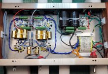
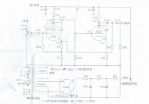
I have put together this preamplifier kit ,
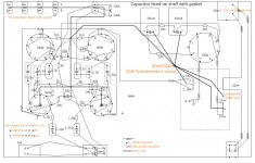
I have a few questions on the grounding that is troubling me ..
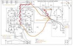
The negative rail of the circuit is connected to the chassis that also acts as a ground for the transformer and the rca connection . basically they all share a ground that is connected to the chassis .
as far as I'm aware that is not a great idea and in my mind can't be that safe ? can someone please advice me on this matter
also one more point is that the earth in the iec ( 230 ac input is not connected in the schematic , I guess if that is connected to the chassis as well that will produce noise into the circuit )
Hopefully someone will be able to put my mind at rest
Attachments
ok thank you for the quick reply . I could not understand why it wasn't added on the schematic and left out
"Are you running the inputs over unshielded wire (red/black at the left) to the input selector? Not a good idea." Spotted that to, better to use screened cable. The RCA wiring is sitting right next to the heater wiring, the signal wiring would be better lifted up out of the way and secured to the wood side.
Lastly all grounds should go to one point on or near to the main negative of the PSU. If using a bus, small signal grounds should go first, then higher current grounds. A 10r resistor from the main ground to chassis can help, it can also be done with diodes.
Andy.
Lastly all grounds should go to one point on or near to the main negative of the PSU. If using a bus, small signal grounds should go first, then higher current grounds. A 10r resistor from the main ground to chassis can help, it can also be done with diodes.
Andy.
thank you for everyones reply's .
I am waiting on some parts to arrive . I am redirecting the on how the ground is ran and I'm using a busbar - not tied to chassis and I'm connecting the earth to the chassis right next the main input .
as for the unshielded rca wires - I'm not sure on this matter I have wound the wires together . if I find it to be a problem I will change them to shielded wires, I would like to point out that I'm still in learning and I thank everybody for there help
Rigers,
I realize it's been a few years since you posted here. Just curious, are you still using this preamp? I've just completed mine and found that it really lacked in the gain dept. I'm trying to see if I did anything wrong by comparing your internals to mine. I noticed that some of the resistors that came with the kit are way out of whack and ordered some better tolerance and higher powered ones. Here's hoping you're still around 🙂
Bet regards
Ron
Attachments
Did you measure the DC conditions? By lacking in gain what is it's OP/IP IE sensitivity? You've done a good job there, nice work.
Andy
Andy
Hi Andy,
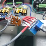
No I haven't measured anything. The only thing I have done is double and triple check my connection points. I have a small hybrid cheap Asian pre that I have compared it to with the same source and my cheap little amp. The factory made pre drives the amp with tons of testicular fortitude while this one behaves like it has no drive at all. It seems contrary to everything I've read of this particular preamp. Folks complaining of too much gain and having to adjust the size of their feedback resistor to tame it would be a problem I could cope with 🙂 . I believe I have a large learning curve to contend with as I know enough to get myself into trouble and how to solder. I saw elsewhere that when shipped in a pre-built state, this preamp comes wired with the volume pot on the output and not the input like the drawings state. Before I put this together I measured the electrolytic caps and they were way out to lunch in their values so I swapped them out with long life Nichicon and the film caps with some better tolerance ones. Can any of these pre-corroded tubes be the culprit? This is my first project but not my last so I really want to get this right before I move on to amplifier kits! Any help or insight would be greatly appreciated!. The vendor on Taobao was no help whatsoever but I imagine the language gap had lots to do with it. I've added a pic of the soon to be replaced volume pot and the input selector wired as called for in the drawing (kinda)
Ron
Attachments
Did they at least send you a schematic?The vendor on Taobao was no help whatsoever
jeff
The same point to point diagram as posted by Rigers above and this one along with some images of the internals of an actual device. These were sent via email after requesting them.Did they at least send you a schematic?
Attachments
Did you try it with the 24k feedback resistor disconnected? Should have a ton of open loop gain.I've just completed mine and found that it really lacked in the gain dept.
Also, what is the input impedance of the amp you're trying to drive with this preamp?
jeff
Last edited:
I
Input impedance is 47k. Believe it or not its just a very inexpensive Aiyima A07 max. Gosh I wish I had my old GAS Son of Ampzilla! See what marriage does? Just kidding! Could it be that simple? Bypass the 24k resistor?
Hi Jeff,Did you try it with the 24k feedback resistor disconnected? Should have a ton of open loop gain.
Also, what is the input impedance of the amp you're trying to drive with this preamp?
Input impedance is 47k. Believe it or not its just a very inexpensive Aiyima A07 max. Gosh I wish I had my old GAS Son of Ampzilla! See what marriage does? Just kidding! Could it be that simple? Bypass the 24k resistor?
That circuit has a rather high gain of 20dB, so there must be a problem if both channels are the same.
Is it possible the volume control is connected wrong, or is a very low value?
Could the feedback resistor be 2.4k instead of 24k? Check some resistor values.
Is it possible the volume control is connected wrong, or is a very low value?
Could the feedback resistor be 2.4k instead of 24k? Check some resistor values.
I hope this is just a mistake on the schematic. Unless I'm very much mistaken, shorting the +245V B+ to ground is not a good idea (circled in red, below).

I found a more full schematic that shows that point (the red circled area in the above post) connected to the B+ of the other channel in the stereo preamp. Perhaps that's what it says in Chinese.
Oops. It did not like the feedback resistor removed. It started microphoning immediately with just a slight tap on the chassis. played ok but higher volumes were truly distorting especially on low notes.
coming so I might just re-do it all. Thank you everyone for pitching in to help! Time to read some more and see if this older fart can learn new tricks 🙂.
They're definitely 24k. Yes both channels are identical in performance. I'll pop the resistors back in and go over what I've done. I have a ton of new resistorsCould the feedback resistor be 2.4k instead of 24k? Check some resistor values.
coming so I might just re-do it all. Thank you everyone for pitching in to help! Time to read some more and see if this older fart can learn new tricks 🙂.
Since the only major difference is the volume control on the output, could it be that? Could you annotate the diagram to show how it was added on the output and what value it is? Is it an audio taper?
There was a thread here some time ago about the pros and cons of fitting the volume control on the input or the output of a preamp. Having it on the input seems more logical to me - the varying impedance of the wiper side of the pot does not matter so much to the input tube - but I will see if I can find the other discussion.
There was a thread here some time ago about the pros and cons of fitting the volume control on the input or the output of a preamp. Having it on the input seems more logical to me - the varying impedance of the wiper side of the pot does not matter so much to the input tube - but I will see if I can find the other discussion.
As mentioned, take some DC readings, it will tell you a great deal. Get a pad of paper, a notebook then write something like this -
HT
Heater V
V1a
g1
k
V2 etc
I'd then get a sig gen or use your phone with a 5 minute 1khz mp3 file then use your DMM set to AC V if you haven't a scope to check AC conditions, same method -
V1 g1
V2 g1
OP
With that info we will know better what's happening. Without data we are just guessing.
Andy.
HT
Heater V
V1a
g1
k
V2 etc
I'd then get a sig gen or use your phone with a 5 minute 1khz mp3 file then use your DMM set to AC V if you haven't a scope to check AC conditions, same method -
V1 g1
V2 g1
OP
With that info we will know better what's happening. Without data we are just guessing.
Andy.
I was part of a discussion with SY about this, in a thread here over 10 years ago.There was a thread here some time ago about the pros and cons of fitting the volume control on the input or the output of a preamp. Having it on the input seems more logical to me - the varying impedance of the wiper side of the pot does not matter so much to the input tube - but I will see if I can find the other discussion.
SY's observation was that if you put the volume control on the preamp's output, its input will be seeing the full output from the signal source all the time. Since in most audio circuits distortion is proportional to level, putting the vol ctrl on the output will have the preamp working with highest distortion levels at all times.
- Home
- Amplifiers
- Tubes / Valves
- hifi 6J4 - 6P6P/6∏6∏ tube preamp


