I've been a bit obsessed with Germanium transistor amplifiers lately. They seemed to be very odd and mysterious things- exotic sounding elements in cryptically numbered long discontinued unobtainium packages, lurking about in funky nerdy cabinets, consoles and 8-track players, long ago disparaged, disgraced, and discarded by the wayside and almost forgotten. Wait- all that weirdness, plus interstage audio transformers and thermistors? Really? I've =GOT= to know more.
I lucked? into two vintage automotive 8-track players for $5 at a trash heap of a garage sale this summer. One was a Kraco in a classy brown wood grain vinyl wrap with chrome face, the other was a Muntz A30 4-track player, minimalist bare bones but in chrome as well. Old madman Muntz was fun to research, what a character he was, and since that one is a little more historic I'll tuck it away on the shelf of tomorrow and play with the Kraco. I despise 8-track, have ever since I was a kid in the 70's. You kick the damn cartridges around on the floorboard until packed with dirt, then jam one in the slot mid song and let it grind and gurgle along struggling to carry a straight tune. Them were the good 'ol days boy. Better than noisy AM radio or your cousin on the harmonica I suppose. Instant fodder for the trash can as soon as you could afford a cassette, like that was any better in a hot dirty car. I could not wait to rip the germanium amp out of that fine brown wood grain vinyl wrap, scrape out the 8-track guts like cleaning a fish, and see how it works. Maybe if it worked well I'll Frankenstein it into a different can to be a kick-about guinea pig test amp. Since it was basically free I did not have anything to lose and a lot to learn.


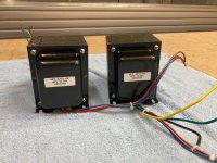
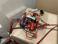
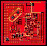
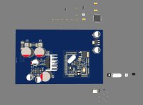
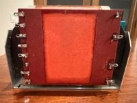
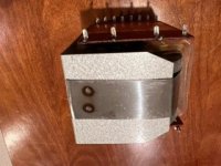
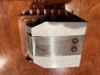
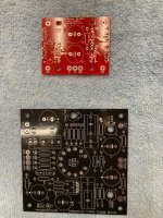
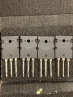
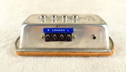
The amplifier was actually a surprisingly good but simple design from Japan. The layout of the amp was excellent and well thought out. The small isolated island of components in the foreground of the left photo is the transistor tape head pre-amp. This whole portion of the PCB was removed as it was no longer necessary. The tape head pre-amp output signal ran up front to the volume, balance and tone pots, then back to the power amplifier across the very back. The left and right silicon NPN transistor pre-driver circuits are at the farthest left and right ends, with the interstage transformers, output biasing networks, and speaker output capacitors as you move towards the center. The symmetrical and well separated layout with a good star-ground strategy was smart, helping to minimize oscillation since the overall gain has to be so high from tape head to speaker. The four totem-pole Sanyo 2SB474 PNP germanium transistors were mounted on the back plate with surprisingly long wire lengths used to connect them to the pre-driver PCB. Only two of the transistors needed a mica insulator, as for each channel one collector (case) was grounded to the chassis and the other collector tied to the output and floated at half the supply voltage (hopefully not shorted to ground by a tool during installation).

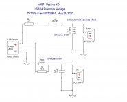
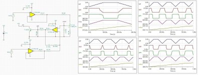
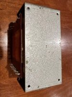
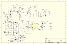
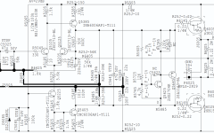
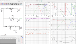
Since I could not find a free schematic for the Kraco KS-408A I hand traced out the circuit, and created the above schematic for one channel of the amp. The capacitor values shown are not the original anemic values- While recapping I have upgraded them to what would be considered appropriate given the smaller physical sizes available today. The original power filter capacitor was 1000uF, now 2200uF, the speaker output caps were 470uF, now 1000uF, emitter decoupling caps 47uF, now 100uF, and the two audio coupling caps were 1uF, now 10uF. All caps have higher voltage rating and are all still smaller than the originals. I moved the output transistors onto a small sheet metal test plate I snipped out of scrap and drilled the appropriate holes through so it was much easier to flip the assembly back and forth while making modifications and measurements.

In the original design there were strangely no emitter degeneration resistors (the 0.22 Ohm on the output emitters) as I had seen in most other comparable designs, even for 12V automobile. First, I had to learn what an emitter degeneration resistor is and does, (Thank YouTube! ). It serves as a small amount of negative feedback to the transistor, with many added benefits- It increases the linearity of the device, helps to stabilize gain, increases the input impedance of the device, and even helps to stabilize bias current across temperature. I decided I wanted to add some. I was not certain if this would force a change to the output transistor bias settings, and was pleased to find that they did not. Without the 0.22 Ohm resistors, bias current ran around 80mA at room temperature, and with them the bias dropped to about 60mA. There was no audible crossover distortion incurred that I could hear, so I just left the bias network alone. It is interesting that both the Kraco and Muntz design did not have emitter degeneration resistors, but did have thermistors to appropriately adjust bias voltage down with temperature to prevent thermal runaway. From the base to the emitter of each driver in the bias voltage divider string was a 20 Ohm fixed resistor parallel a 22 Ohm (at room temp) thermistor. The thermistor decreases it's resistance as temperature rises, decreasing base-emitter bias voltage when hot. I suppose the tiny thermistors were considerably cheaper and easier to accommodate than four larger ceramic emitter resistors mounted to the chassis. It is interesting to note that when I see thermistors used in this way in germanium amplifiers, it is typically a fixed and thermistor resistor of comparable values in parallel- This must provide the optimal temperature gradient, or maybe provide safety if the thermistor were to fail open? Interesting.
In my initial testing, using a full line level signal from my media player into the Kraco volume pot it was incredibly difficult to get a reasonable listening level with the volume pot just off the stop. The gain was way too high. In checking the schematic I found the first stage Q1, a basic H-biased common emitter stage had it's 1K emitter resistor fully bypassed with a 100uF, so it's gain was spun to the moon (2.7K / "little re") so it's cranking. I might understand this if it were contributing high open loop gain for inside the feedback loop, but it's outside the loop, so holy cow. The signal level coming out of the tape head pre-amp must have been very tiny indeed. Imagine how much noise must have been picked up shipping this tiny signal up front, through three different pots then back and into this very high gain stage. As a first pass, I simply removed the 100uF capacitor from across the 1K, dropping the gain to 2.7K/1K or 2.7X. That did the trick nicely. Now with full line level volume coming out of my media player the amplifier is at a strong but comfortable output level with the volume pot about half-way up. Feels about right, I might increase the gain a little bit later in fine tuning.

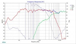
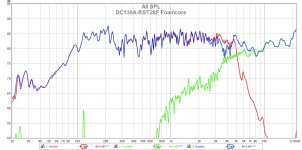
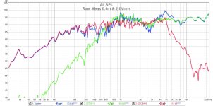
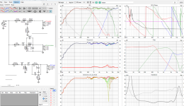
The next issue I found in my initial listening was that the high end was really rolled off. None of the crisp detail I should hear in my Sony SSCS5 test speakers, which are noteworthy for high end detail. I did finally find some specs at least on the Kraco, and it listed bandwidth from 100 to 8Khz. I assumed this was so sucky because of the 8-track head bandwidth, not the amplifier. I have certainly improved on the low end by increasing the coupling and output capacitors, but 8Khz seems like a joke. Referring to the schematic, I see they have a resistor/capacitor shunted across the primary winding of the interstage transformer of .015uF (15nF) in series with 3.9K. This would act to decrease the impedance of the winding and reducing the gain into the transformer at high frequencies. The f3db of the shown values is about 2.7Khz so that would be quite a roll-off. In reviewing several other designs I see that they either did not have this limiter, or if they did the f3db was more like 15-20Khz, limiting ultrasonic frequencies but not really audible ones. Certainly this was to prevent amplifier oscillation, and given the high gain of the input stage, shipping the tiny input signal all around the chassis, and the really long wires between the predriver and output transistors this heavy handed measure was probably necessary. I decided to test a higher f3db by changing the 15nF to a 2.2nF, for an f3db of 18.5Khz. I did not want to change how much correction this RC circuit applied, so I did not change the 3.9K, but adjusted the capacitor to change only at what frequency that 3.9K came into play. No oscillation was detected under any condition with my little pocket oscilloscope, and the high frequencies were MUCH better. Still not quite where they need to be, but much better.

Speaking of high frequencies, another area that would really need attention if I wanted to clear the cobwebs and make this into a higher fidelity amplifier would be the two 0.015uF (15nF, 15,000pf) capacitors from the base to collectors of each output driver. This capacitor is typically referred to as the compensating, or dominant, or Miller capacitor. It is used to prevent amplifier oscillation by setting the dominant upper frequency limit (and slew rate) of the amplifier to within a stable range. These values as shown are REALLY high. In some designs these are as small as 10 to 100pf instead of 15000, and generally only on one driver, not both. (I can't help but wonder if the Japanese manufacturer had a surplus of 15nF caps and just decided to use them everywhere they could.) Oscillation in an amplifier is just like feedback into a microphone on a PA system. Get the mic just a little too close to the speaker (increase coupling) and the high frequencies race in a loop causing a screech. In an amplifier however, this can be ultrasonic, you won't hear it or even know it's happening until the amplifier or speakers start overheating and smoking, and you need an oscilloscope on the output to even detect it.
Adjusting the value of these capacitors generally takes some iteration- You replace them with smaller and smaller values until you reach oscillation, then back off a bit. You don't know at what value oscillation can occur because it is highly dependent upon the gain, exact nature and amount of wire to wire coupling you have inside the amplifier, temperature, and use condition. You have to be really careful with this, and not tread too close to the edge, because if it's stable and you button it up, and it goes into oscillation under some other temperature or use condition it will cause damage. I think the fidelity of the amplifier as it is right now is sufficiently good I'm not going to mess with these right now. Considering the relatively long wires connecting the output drivers, I think the designer was overly cautious for a reason.

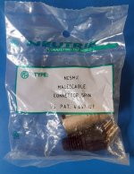
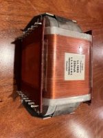
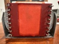
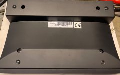
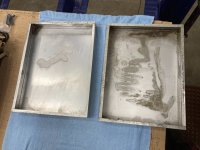
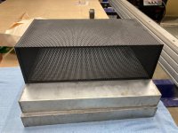
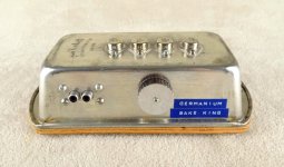
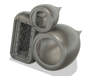
I didn't want to spend the money to buy a fancy aluminum box for this amplifier, so when I found a couple of tin plated steel bread pans (the small ones, like for zucchini bread) I could not resist. "Bake King - The King of Bakeware" was stamped into the bottom. The Bake King was born! I cut away the unused areas of the PCB (previously for the tape head pre-amp and the huge supply filter capacitor) and the PCB fit beautifully into the bottom of the pan. I used the hole pattern from the original back plate to mark and drill the transistor holes, and mounted the transistors sandwiching my sheet metal test plate underneath to give a little more thermal bulk. I used a Dremel tool to cut out the square hole for the speaker connector, which was an old AM/FM antenna connector block. The pot and chrome volume knob are from the Kraco, the input RCA terminals from an old console, and a chunk of scrap plywood. I tacked the PCB ground trace that ran around the outside edge to the inside of the pan with a soldering gun to hold it in place.


I power the amplifier with a switching 18V @ 1.5A wall wart, with an output plug that matches the power adapter jack from my scrap box. I have to say- it sounds pretty good, certainly better than it did as an 8-track player. The Kraco specs indicate it will drive 4W into 4 Ohms, and I have confirmed that with my 4 Ohm resistive load and pocket oscilloscope. Obviously it drives less into 8 Ohms, and sounds best under 2W. It's small, super easy to set up, and great for testing speakers, source components, or rigging up a test lead with alligator clips to test capacitors in series between the output and the speakers. It was a great exercise for learning about the care and feeding of germanium transistors, and I'm into it all of about $4 for the 8-track player and Bake King bread pan. Everything else came from scrap. Hope you enjoyed the journey with me, and remember, always "bake until golden brown".
-Warren


