Newbie DSP crossover confusion

Hi,

So as I understand it passive crossovers work in the analog domain (capacitors, inductors...) and DSP crossovers work in the digital domain (ones & zeros).

I now understand that its called a crossover for a reason, there is an overlap where both drivers are outputting. I thought the overlap was an artifact introduced by the passive nature of analog, that it just wasn't possible to have a woofer low pass at exactly 1999Hz and a tweeter high pass at exactly 2000Hz?

Recently I learned that you design a DSP crossover using a passive crossover designer like WinPCD and then essentially import that into your DSP? This suggests to me that an overlap is necessary or at the very least advantageous?

In my mind a DSP should surely be able to low pass a woofer at exactly 1999Hz and high pass a tweeter at exactly 2000Hz because its just data bits, it seems nonsensical to go to all the trouble of creating a passive crossover for a DSP crossover implementation, in CamillaDSP the crossovers seem to be FIR, why can't I just create a crossover widget and type in an exact frequency?

So I must be missing something, I'm guessing its to do with physical limitations when the audio goes into the analog domain, maybe its to do with physics, deceleration perhaps, that you cant make a driver going full-bore stop instantly so you have to compensate by gradually slowing it down?

Thanks!

Eico HF-32 mono block iron for project

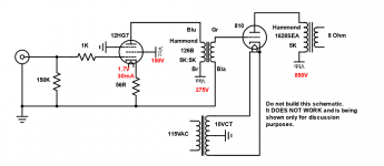
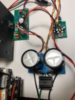
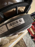
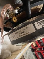
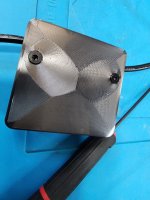
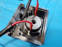
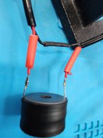
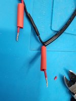
I have a set of OTs and a set of PTs from Eico hf-32 mono blocks. Interested more in using for power amp only.
Any thoughts on a good circuit for this iron?

Attachments

  • P_20220126_134338_p.jpg
    P_20220126_134338_p.jpg
    412.4 KB · Views: 69
  • P_20220126_134456_p.jpg
    P_20220126_134456_p.jpg
    477.4 KB · Views: 74
  • P_20220126_134213_p.jpg
    P_20220126_134213_p.jpg
    466.5 KB · Views: 65
  • P_20220126_134221_p.jpg
    P_20220126_134221_p.jpg
    455.5 KB · Views: 73

Meanwell RS100 24 thermistor/ICL blown to pieces

I have 2 of these PSUs in a chassis , each powering a channel of Abraxalito' s class D amp.

Stacked on top for packaging. I initially removed the cover from the lower one for air flow and cooling reasons. Not that they get particularly hot.

Been fine for a couple weeks then came to switch it on ( mains switched with a latching push button) recently and got a healthy pop from inside the case. Couldn't really tell what, but it all seemed to be working. It's done it a few more times and got to a point where the switch wouldn't switch it off so I assumed something in the inrush had fused the switch shut.
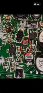
Thought I better had look into this and have just taken the lid off, and off the offending PSU. It would seem to have eaten up the ICL on what I assume is the main 240v in. Not exactly a big load from this class D amp. And the switch seems to have 'recovered'!
Any thoughts on this?. Shall I just replace it? What sort of value and do I uprate it.? It all still works but a shower of sparks on start up isn't so family friendly! The PSU states 100 to 240vac and I'm pretty sure I'm around 245 a lot of the time, but I doubt this is the cause.

Attachments

  • IMG20241009190956.jpg
    IMG20241009190956.jpg
    226.9 KB · Views: 97
  • IMG20241009191005.jpg
    IMG20241009191005.jpg
    254.9 KB · Views: 92
  • IMG20241009191031.jpg
    IMG20241009191031.jpg
    398.8 KB · Views: 88

  • Locked
Calculations are mud

Do you know how inaccurate and crazy it is too calculate the parameters of a speaker?

There is not even a closed form for the Navier-Stokes equations.

https://www.claymath.org/millennium/navier-stokes-equation/

This has been an open problem for more than a hundred years, and you think an equation can help you design a speaker? 🥹

Trail and error. That is the only effective off-peak principal 😎

Really, how bad is this 3-way "voice" issue?

Hi,

Apologies, I cant really link to where I read this because I cant find it anymore, I think it was in a thread about advantages of MTM (2.5-way?) over 3-way on this site somewhere. It stuck in my mind though.

Be gentle, this is from memory, it went along the lines of a 3-way woofer and midwoofer will have different "voices", membrane size, cone material...so when you XO right in the middle of a female vocal range part of the singers range will sound "different" as it crosses drivers, meaning you have to take care with driver choices so they match?

My question is how big of an issue is this really, can it be measured, is it audible to non golden ears, can it be "fixed" with DSP crossover (I doubt I'll ever build or buy a passive crossover), reason I ask is I feel "soured" against 3-way?

Manufacturers are reinforcing this because they seem to have moved to sexier MTMs and coaxials (sometimes with added big bass woofers).

I know this is somewhat subjective.

Thanks!

Getting a lot of noise, not sure if I'm blowing out the speaker or something else?

I'm working on building a portable self-playing "box" I can use to add sound effects or ambient noises to an area. I got everything working but I'm getting a ton of noise on the speaker and not really sure what the source is. Am I blowing out the speaker? The in-line potentiometer? Switching power supply?

Any feedback would be appreciated.
SpeakerBox Wiringv2.png

Attachments

Trying my mod chops: Can't get consistent schematic. Anyone want to help?

Hi all! I'm in the process of trying to mod the crossover of a 2-way Klipsch KPT-1260H. I pulled the crossover and have drawn it four time with different result each time. 🙁 I was wondering if anyone would be will to draw the schematic for me as a second set of eyes? It's my first time trying to draw and existing crossover from a printer circuit board.

Both side of the board attached. I've labeled the lead on the components.

"I" = inductor.
"C" = capacitor
"R" = resistor

Additionally I've labeled the inputs and the outputs.

Anyone want to draw it for me?

Thanks!

Paul

Attachments

  • 20240924_131216.jpg
    20240924_131216.jpg
    321.6 KB · Views: 77
  • 20240930_214004.jpg
    20240930_214004.jpg
    401.1 KB · Views: 76

What is the best TPA3251 board currently available

Hello everyone,

I am looking to purchase a TPA3251 board from eBay/Ali. Which board would you recommend? I have read the last 100 pages of the thread titled "TPA3251d2" and all pages in the thread "Aiyima TPA3251 Modification Build Thread !", but could not find the definitive answer to which board is the best.

Unfortunately, 3e Audio does not appear to have any TPA3251 boards in stock, so I am looking at other implementations.

Here are some examples:

1. TPA3251 HIFI Digital Power Amplifier Board Dual Channel 175W+175W Class D Audio Amplificador For Home Theather|Amplifier| - AliExpress

2. TPA3251 two channel digital power amplifier board|Amplifier| - AliExpress

3. TPA3251D2 Digital Power Amplifier Board 175W+175W High end Stereo HiFi Audio Amplifer Class D DC24 36V|Operational Amplifier Chips| - AliExpress

Ripol and room acoustic

I am thinking to add a subwoofer to my system and played around with REW to figure out best placing of subwoofer(s) in my room. I found that the best location would be center on the back wall and a second center front would help but not by much. I think all these simulations assume a pressure driven subwoofer design (my preference for that would be closed). I am also intrigued by the Ripol subwoofer design after reading about it almost 3 decades ago but never heard one. I understand in contrast to standard subwoofers which act as a monopole Ripol design has a semi cardioid pattern so normal subwoofer placement advice maybe not applicable. I did not find any good advice on Ripol placement even by the few companies which produce variants commercially. More design discussions I find here but in the pictures I see the placement is close to the wall and main speakers but I am thinking there should be a relationship between the out of phase back wave and wall reflection.

So I would appreciate any insight into Ripol placement and interactions with room and main speakers (mine are on wall design).

JVC JA-S41 relay not engaging

I've got a JVC JA-S41 integrated amp that will not engage the relay. It's been completely recapped and some of the transistors have been changed or replaced due to previous owner. Plugged into DBT and the relay is being feed 48 vdc. There are 2 transistors that seem to be controlling the relay X624 and X625. According to the schematic is is suppose to be 9.9 vdc from the collector of X625 and 6.9vdc from the emitter. The collector measures 48vdc and the emitter is .6 mv. X625 was originally 2sd438 and was replaced with Ksc2383 and X624 is KSC1845. I have attached the schematics and any help or ideas would be appreciated

Attachments

For Sale 3D Printed holders for the UcPure Power supply

Hi all

I have previously made a "swap Meet" for selling this 3D printet holders, but I think I would be more easy to have it in a Group Buy since everthing is displayed at the top of the thread instead.

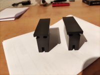
This Group Buy is for a finished 3D printet set of holdes for the UcPure Power supply made by IanCanada: https://iancanada.ca/products/41c-ucpuremkiii-ultracapacitor-power-supply

If you have a 3D printer your self, you can download a free file here: https://www.thingiverse.com/thing:6578689

I have decieded to make a smaller batch for those not having access to a 3D printer and here is the pricing:

UcPure holder price

Small batches will be made. Please allow up to one week or more before shipping (usually much faster🙂).

Please send a PM of how many sets you would like to buy, color, type of PayPal payment, where to ship to and your email🙂 I will get back to you with a total cost. You are also welcome to contact me at: miklau.dk@gmail.com

1 set = 4 pieces (2 upper & 2 lower) to make one UcPure Power supply.

1 set: 14€
3 sets: 39€

1/2 set (two lower bracket only - use zip ties to secure caps - for low height enclosures):10€

Types of colours: Black, Grey or White (looking for an another colour? Send me a PM, maybe I can work something out)

UcPure Center Piece price:
The center piece will be assembeld and fused together before shipping. You will need 1 set of Center Piece and 1 set of original UcPure holder to build one UcPure Double/Quad:

1 set: 15€
3 sets: 42€

Extra:
Set of screws for one UcPure and assembly (4 x M4 nuts and 4 x M4 screws).
1 set: 2€
3 set: 5€

(two sets of fasternes is required to build one UcPure Double)

Shipping

Recommended Letter - Worldwide (with tracking and insured up to 34€):

1-18 sets: 23,5€ (0-2kg)

Package full insured - Worldwide (outside of EU)
1-8 sets: 41€ (0-1kg)

Package full insured and with tracking (GLS - within the EU):
1-8 set (0-1kg):
15€ for the following countries: Belgium, Holland, Luxemburg, Poland,Sweden and Germany.
18€ for the following countries: France, Finland, Czech Republic and Austria
25€ for the following countries:Bulgaria, Estonia, Ireland, Italy, Croatia, Latvia, Lithuania, Portugal, Romania, Slovakia, Spain, Hungary and Slovenia.

I will accept all types of payments with PayPal for the above shipping methods. Please add 5% to the entire order including shipping if a regular PayPal transaction is preferred. “Friend to friend” transfer (no fees) is also acceptable but entirely up to you.

Shipping by letter (PostNord):
Possible but no tracking, no insurance, long lead time AND at buyers risk:
1 set: 7,5€ (100g) - Worldwide
2 set: 14,5€ (250g) - Worldwide
+3 set - use recommended letter - Worldwide

With this method please accept terms above and will only receive “friends to friends” transfer from PayPal.

All parts are shipped from Denmark.

large_display_3a279c24-9846-4947-84b2-38ab0311f822.jpglarge_display_16806e19-dec7-474f-a6fa-3d98acaf4dd7.jpglarge_display_IMG_4308.jpglarge_display_IMG_6574.jpg
  • Like
Reactions: uncola and Ripster

Help Selecting 2x75W Board for 24VDC Supply (or something)

Hi, I'm working on a box that has a Dayton KABD-250 running things, which likes 24VDC 5A. I need to add two more-powerful channels, >/=70W RMS into 6Ω, whatever that translates to in chip amp marketing specs. HF performance is not needed, LF is. So... how do I pick a good board or kit for the extra channels? Looks like I could get a 15A 24VDC supply and try to find a 24VDC amp, but most the higher output ones seem to want 40V+? Should I use a higher voltage supply and and drop it to 24 for the Dayton board with a transformer?

I'm a speaker guy, not great at this stuff. Thanks in advance for anyone willing to give suggestions.

Technics SL-1210 Mk II hummy noise

I've a Technics S:-1210 Mk II that has a low level (but quite noticeable) noise on the audio output that I think is either being induced into the cartridge but only when the stylus is in contact with the vinyl (or platter) or, is vibration, albeit not audible, that the transformer is causing in the platter?

Things I know and have checked:

1. It's not mechanical/bearing rumble - the noise is present when the unit is switched on but the motor not running/platter not spinning.
2. The stylus must be in contact with the vinyl or platter for the problem to appear. Just being near the vinyl/platter doesn't cause the problem.
3. All the grounding seems correct and intact - the problem was present when I got the unit which had the mod some people do with grounding via the signal grounds and no separate wire. I've re-instated the standard separate ground wire scheme but no change.
4. The noise is not plain mains hum - it sounds like there are higher frequencies imposed on top of mains hum and I can see that on a scope . It's not random noise.
5. All other wiring seems OK - the signal and ground wires all seem good.
6. The problem is on both channels.
7. I've tried a different cartridge - same result.
8. Everything works OK otherwise.
9. The platter itself does not appear to be grounded but grounding it made no difference. (I wondered if it acted as a screen to the power supply).

Any ideas?

Universal tube preamp PCB, ECC99/6N6P/ECC88/ECC85/6922/6DJ8 etc. MU follower or SRPP

After 18 years challenging myself, learning from you and sharing nice projects I will leave this forum.
Also because being bullied and get physical threads without support of the moderators for the last 18 years.
See you all on the next forum.

R.I.P by mod.

digital noise and save issues of Nvarcher Bluetooth 5.0 DSP with Mvsilicon BP1048B2 chip

Hello.
I bought the bluetooth DSP Blenchance 2.1, when I save my settings the red light does not flash twice, but if it is saved for several minutes/hours, after that period of time it reverts to a completely random setting.

Additionally, it presents digital noise that can be easily perceived at low volume levels.

Does anyone know how I can correct these problems?

I am using ACP Workbench to configure it.

Attachments

  • nvarcher (1).jpg
    nvarcher (1).jpg
    127.8 KB · Views: 85

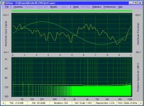
Filter weirdness

  • Generating a 50hz tone with harmonics in REW
  • Recording with a u-mik1 on Smaart
  • In MiniDSP, I set a 10hz high pass Butterworth 36db on my mains. I expect it does nothing, since my mains don't go that low
  • Instead, when the filter is enabled, I see a 5db attenuation at 50hz.
The system is running two mains and two subwoofers. When this was generated, the mains were running full range, and the subs had a high pass at 25hz and low pass at 155hz. The mains have a 3db drop off at 40hz.

This is a MiniDSP Flex Eight HTX. Do I not understand how filters work or is MiniDSP doing something wrong?

Attachments

  • 50hz.mp4
    1.9 MB

Troels Gravesen Faital 3WC-10

Hi

Been away for quite some time. Thinking now I really want to build a new set of speakers.

The build I'm thinking about is the Faital 3WC-10 from Troels Gravesen. I find several builds of the 3wc-12 and the 3wc-15, but none of the 3wc-10.

Reason for choosing the 3wc-10 is size.

Is there anyone here that has built this?
Will it sound more or less the same as it's bigger "brothers"?

Tweeter phase for first/second order crossover

I am working on some speakers that have had the bass driver swapped out and sound like they are lacking in mid range.

The tweeter is a Vifa D19SD which seems to be a higher power version of the D19TD that I understand is usually crossed over at around 5kHz.

The crossover has a series 3.3uF cap and inductor (unknown value) across the tweeter, and a series inductor (unknown value) for the woofer. So a combination first order and second order.

I don’t know what the original woofer was, so am only guessing re what the crossover frequency is.

The replacement woofer looks designed more as a subwoofer and has a stated range to 4KHz, 91dB efficiency (vs 89 for the tweeter).

So….I wanted to confirm that for this crossover design, swapping the tweeter phase is not going to make any difference?

If the previous statement is true, then the only way to recover some midrange is to drop the crossover frequency, so I was going to try a 6.8uF cap to start, and adjust by ear. Potentially lose some power handling capacity.

These are freebies for my niece so not trying to get them perfect, or to invest too much into it ;-)

Caps in crossover for midrange question

Hi Thanks for reading I'm using a single 10uf cap in series with an 8 ohm midrange unit, giving a crossover frequency of 2khz @ 6db/octave

I had bright idea of replacing the single 10uf cap with 10 x 1uf wima polypropylenes, i thought with so many caps paralled up it might give lower esr and reduce some of the other undesirables elements of caps. Now the sound is all weird, sounds wrong, i don't know what is going on.

Have you tried anything like this before, or heard anything

SEAS Tweeter voice coil replacement

I have some old Interdyn 10” 2 ways with a SEAS H211 tweeter, one of which was cooked.

I measured the magnet as 25.4mm and ordered some replacement voice coils/domes for a 1” tweeter and what was supplied was a voice coil that is also 25.4mm - which does not fit in the gap in the magnet.

Should I be ordering a different size, or should the 1” dome voice coil actually be a little bit bigger?

PS schematic help?

So a little background. I have used AB International amps in the past and have recased a couple of 600As to power my modded Carver Amazings and they sound amazing. I’m now on a mission to recased a 1100A to power my sub towers.

I purchased one cheap none working. When I got it some of the power supply caps where installed backwards and burnt up a couple of the main traces between the transformer inputs and the rectifiers. I fixed the traces and installed new main caps. At J2 I have HV=109ishvolts at pin 5 and 7 to ground. I also have LV=53ish volts at pins 4 and 8 to ground. My question is could anyone tell me what the voltages should be at pin 2 (mute) and pin 3 (latch)? Any help would be hugely appreciated!View attachment 1361934

Attachments

  • IMG_7508.jpeg
    IMG_7508.jpeg
    310.5 KB · Views: 95

Tiepie and bode plot

Hi
I recently use a Tiepie HS5 usb oscilloscope.
I'm trying to measure the response of amp, output transformer or filter.
Apparently there is no fast tool for bode plot (phase and magnetude response measurement).
I find a solution for magnetude response/fréquency with "Math" tools but nothing for phase response
Is anyone using another solution ?
Thanks for help
Yan24

[Mod] De-emphasis LED indicator
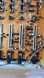
Hi folks! The best remedy for boredom is to find something to do... and I think I've had a good idea:
I have a few CD's in my collection mastered with pre-emphasis. Obviously CD players are able to detect the emphasis flag and then enable de de-emphasis circuit.
I have a "small" collection of philips cd players and most of them uses the SAA7210 decoder which has a DEEM output (leg 32)to activate de de-emphasis mode in the cd player.

My idea is to add a led indicator to tell the listener if the de-emphasis circuit is turned ON/OFF.

As I said, in the case of the SAA7210, the leg 32 (DEEM) brings a voltage between 2,4V and 5,5V as a HIGH value to activate the de-emphasis circuit. This DEEM is connected to the de-emphasis circuit as shown in this picture:

Captura de pantalla 2024-09-28 a las 9.17.27.png


I need ideas for this complementary circuit. I know that I cannot put a led + resistor from DEEM led to GND because it will drain a lot of current from the DEEM leg an may burn it or burn the decoder.
Any idea? Thanks for helping!!

Open baffle midbass

I've been using my OB system for a good while. It runs 4 sealed 12" subs below 80Hz, a nude OB 18" Faital Pro 18HP1010 up to 300Hz, B&C 8PE21 in OB, and Beyma TPL-150H open in the back. The system is active and I use Acourate to develop the filters to get to the target in-room response. At the time, I purchased the 18" to try OB out, and I like the midbass definition that OB brings, but I'm missing the "body" unless I turn it up quite a bit. I don't think it's a matter of amount/SPL as the system delivers on the target curve, but there is something missing unless I turn up the volume beyond what is acceptable while others are in the house. With good records and volume turned up to 90dB I get the grin in my face, but then that's not too often.

The Faital is not particularly well suited for OB. Nor I think I need a 18" midbass. Thinking 12" or maybe 15". I was planning to upgrade to something like Acoustic Ellegance LO12, SB Bianco, or Beyma 12BR70 used in the Caladans, but my current experience has me hesitating. I read references to OB bass being more often liked for classical and jazz. While I listen to both, I mostly listen to rock/blues where kickdrums and bass guitar play a significant role as well as synths.

Looking to get input from experienced users. You like OB midbass and like rock, compared to sealed midbass? Is the poor choice of the Faital as OB midbass a likely explanation for what I'm (not) hearing?

Thank you!

@maxolini

@maxolini Is getting quite good at illustrating these 6th order parallel boxes. I thought it appropriate to aknowkedge/appreciate him as he’s very willing to do this for persons who have existing designs and can help him develop his CAD skills.

I wish I could just scale up the size and proportions to any driver but it’s very intersting how different things like the 18ds115 or dayton audio Ultimax under/over damp the heck out of things that end up so ‘perfect’ with some drivers .

I also find it intersting to geek/nerd out on that cancelation frequency and the other resonances and find they’re directly related to the actual distance between the drivers(I’m new at this)

Attachments

  • C1A5AEA3-C340-4282-90F5-B6C81B6BDD14.mp4
    2.9 MB
  • IMG_0610.jpeg
    IMG_0610.jpeg
    72.1 KB · Views: 41
  • IMG_0609.jpeg
    IMG_0609.jpeg
    91.7 KB · Views: 42
  • Thank You
Reactions: GM

What's the white stuff?

The attached is the back of a USB hub that stopped accepting power from the wall wart. I took it apart because I can't help myself and was wondering what the white stuff was on the hand solder on the board mount USB sockets. It's easily scraped off with a finger nail and I assume its flux residue, except that there's the more normal flux residue there as well and it's only on the pins that're connecting the socket case to the board.

Any ideas?

Also it's quite a juxtaposition between the supreme tidiness of the oven cooked smd and that messy hand solder. Though, that said, I do miss the opportunity to scavenge parts. I can barely see some of those capacitors, let alone desolder them for reuse...

Attachments

  • Back of usb board.jpg
    Back of usb board.jpg
    375.9 KB · Views: 124

Static noise

I'm trying out a cheap r2r DAC from China. Unfortunately it has static noise like a not tuned in radio. If I turn the volume up the sound suddenly at a certain volume becomes clear but the lower volume noise stays. Every instrument and voice above a certain volume is crystal clear but instruments and voices that are lower in volume are really distorted. All at the same time in a song.
Never experienced anything like it before.

Unfortunately there is no schematic available from the manufacturer.

The phenomenon is less with the supplied muse opamp and more so with my discrete ones.

Connected via coaxial cable from my Wiim Ultra feeding a Chip amp with currently no preceding volume pot.

I know it's hard to figure from a distance but maybe someone else had experienced the same phenomenon and figured out how to fix it.

Thanks in advance.
Klaus

Greetings from Bangkok, Thailand

I'm new to this community. Love to built things and now exploring audio equipments. I've been paying ridiculous amount of money to big brands for a long time. Recently I've ventured in to my first DAC DIY project to find that with a lot of research, I can make a $1000 DIY project sounds better than a $7000 DAC (to my ears anyway).

Hope I can learn more from the community here.

Hello from Minnesota

I'm an amateur speaker designer working on my first 3D print of a loudspeaker waveguide for my first build. Definitely not there yet, but I'm making progress; progress that will hopefully go even smoother with the help of the kind folks here 🙂

Should AKABAK be used with an interface on the front of the waveguide, or without one? And if so what shape should it take? I seem to get very different results depending on what my setup is, and it's not clear which one is right.

example.PNG
details.PNG
dispersion.PNG
  • Like
Reactions: Speedysteve7

A big hello from sunny Scotland!

Hi folks. I have been up late at night searching for ceiling speakers for my Atmos Receiver and chances upon a thread discussing my old Tannoy Mercury M2.5s.

I have pictures to prove the components that were unfortunately burnt to a crisp on a fellow forum dweller's speakers.

Ended up repaired the old things just minutes ago with some shiny new washers. Now it's time to get my Wharfedale sub thumping again. Or perhaps I'll just go to bed! It's soo late...
  • Like
Reactions: grindstone

Technics SA-5070 multiple issues

Hello everyone!
Below a pic of my beautiful Technics SA-5070 it was a pain in the *** to find the right light bulbs to make it look like this (see picture)

IMG_20240916_174902.jpg


But unfortunately I have some other issues or let's say questions.

Often when I found a station and listen on it, the station disappears and comes back multiple times. Then I have to rotate a little the tunning knob until I get a good hold of the station again.
What could be the root issue for that?

The Antenna what I use is 300 Ohm dipole fm Antenna ( I don't know if I can put the link over here... It is bought form the known big chinese store with the three letters starting with an A )

See picture that follows:

Screenshot_2024-09-16-21-45-30-998-edit_com.alibaba.aliexpresshd.jpg


However I am not sure if I connected the antenna correctly. See next picture:

IMG_20240916_182510.jpg


Another issue is that I feel the tunning knob very hard in compare to other vintage tuners or receivers.
No picture for that!
What could this be due to?

...and the last important issue is that I didn't find until now a free service manual for this beautiful peace.


Thank you in advance for every advice or help!
🙂

Please check my crossover design

Hi, I'm building my first set of speakers using a set of Faital 12FH500-4 horns and Faital HF206-6 compression drivers. I am using these components primarily because I got them ridiculously cheap and I've heard goods things about Faital. I plan to use a sealed enclosure.

I've never designed a crossover before, so I'm hoping if folks could chime in on the the attached photo, which shows my proposed design. I want to reduce the horn volume by 6db to start, so I included an L-pad. I also included a zobel on the woofer. The crossover point is 1,000hz.

Thanks for your help.
20241007_113111.jpg

Restoring Wharfedale W3 speakers

Hi,
I live in the Golden Triangle of Yorkshire Hi Fi home of Sugden, Wharefale, Richard Allen, Castle...and others. I'm fascinated with their products from the 60's and 70's. I recently picked up a pair of W3's and today I dessembled them intent on restoration. Please could somebody help me by telling me:

1. why the 12" drivers have polystyrene glued into the cones - see picture? Should I remove this?

2. The Super 5 and Super 3 drivers have felt annuli. Should I replace like for like or 'upgrade' to foam or rubber?

Thanks in advance.


IMG_5362.JPG

Looking for quality crimps

Way back when I was working in car stereo (the 1990s) we used insulated butt connectors to wire up head units, speakers, etc.

The crimp connectors we used had a thick tube of tinned copper inside and required a lot of force to change its shape. When you squeezed your crimp tool (with all the strength you had) the ferrule would bite down on the wire so strongly that the wire would break before you could pull it out of the crimp. The forces were so high that the wire and the crimp became a single piece, and the electrical connection was as if the two parts were welded together.

Recently, I have tried numerous crimp connectors from many different sources and have yet to find a brand that used anything but the thinnest, weakest alloys for the ferrule. They don't squeeze around the wire nearly as tightly, and they spring back after crimping. I can easily pull the wire out of the crimp without any force.

Also, a female quick-disconnect we used would be very hard to slide onto a speaker terminal. You had to brace the terminal mount with your fingers or you'd break it off. This left a strong spring-loaded squeeze on the terminal, and probably also scratched through the oxidation/tinning layers to bite down on clean metal, making a secure contact.

I'm looking for female 10-12 AWG quick disconnect terminals like these again. Anyone know of a good source?

Hello from Japan

Hello.

I'm oGiNuno (this is my online name).
I'm a college student now.
I'm Japanese and I've never been to other countries.
So please let me use my poor English.

I fortunately had many chances to go to a science workshop (when I was a child).
I enjoyed these activities and I especially attracted to electrical engineering.
Then my parents bought me a book about how to use transistors.
And one of the examples of the book was making an audio amp.
This is the first time I met to make audio devices.

Best sound device I own now is old fashioned multi bit DAC(PCM501ES made by Sony).
I bought it at a secondhand shop and I repaired by myself.
I don't have other good devices (because I'm still a student).

I'm using Sound ID Reference for speakers and headphones.
I think calibrated sound is good.

I'm now planning to make my first original analog amp to use with the DAC above.
And my dream is making multi way DAC and speaker system.

My favorite artists are :

Queen
Paul Rodgers
LMFAO
Dakota Star

And I love game bgms(Metroid, Kirby,HALO,and so on).

I want to learn many thing from this community.

Thank you for reading!

Understanding nearfield separation & bass

Hi,

So I'm trying to figure out the best way to build speakers for music and gaming, my computer monitor is as wide as my desk and so the speakers will have to go just above the monitor angled down a bit.

For nearfield, I'll be less than 1m away, how much stereo separation would I need, is 1m sufficient?

I would like punchy explosion and gun fire effects, what size of woofers would I be looking at, ideally the speakers wouldn't be too unwieldy?

I'm thinking that if there was separate HF (for this application maybe I don't care much about over 4KHz?) that you would want to be very near the woofer or even coaxial?

I could maybe have some sub bass behind the desk.

How would you approach it?

Thanks!

Best DIY CLASS AB

Hi all

As DIY forum has been resourceful to many enthusiastics around the world i would like to take experiences to a single thread. So in the future if anybody visit the forum could get a idea about different designs. I'm also one of them, a novice.

Please share your class AB experiences of DIY forum introduced builds. There adding measurement results SQ etc. if you have would be a good help for the research.

If you have done any personal modifications please tell that also.

Need help with the tuning section of a Kenwood KR-6600

Hello,
I'm an absolute novice when it comes to tuners and radio reception in general. However, I have a lot of experience with amplifiers and other electronics and I'm also talented at tinkering, so I'm looking forward to any tips on what to do...
About the problem:
I overhauled a KR-6600 and the only thing that still doesn't work is the tuner. There is only a noise and neither the tuning nor signal display moves when searching for stations.
IC HA1137w and HA1196 have been changed, transistors and that FET-thing in the tuner section checked (they are all ok), but errors are still there.
Now I noticed that if I touch pin 1 of the HA1137W with my finger or the tip of a screwdriver, the signal display moves and a distorted station can be heard, but only this one. When I turn the tuning dial, this one station remains distorted and nothing else happens.
What could that be, or where could the error lie? Once again, thank you very much for your effort and have a nice day everyone

NAD C455 DAB Tuner with Crazy Hot L7812 regulator

I have a NAD C445 tuner. I have recently one of the voltage regulators as it was broken. It is not up and running.

There are four existing voltage regulators which are getting very warm and causing teh tuner to consume 40W:
  • IC91 L7805A with sizable heatsink for FM/AM Amp
  • IC92 L7805A with sizable heatsink for OpAmp
  • IC93 L7912 for DAB
  • IC94 L7812 for vacuum flourescent display

Regulators IC94 IC91 and IC92 and getting to 75C. In particular IC94 is getting hot without a heatsink. There is a relay that is getting to 45C. The tuner otherwise works fine.

What could be wrong?

Do I just need to replace all the regulators?

Many thanks, George

1728417311941.png

Longtime audio DIYer from Seattle, WA

Hello! My name is Lowell, that's pronounced like lowl or lole ...or lol. 🙂 Actually, it's supposed to be two syllables, like "low-wuhl," but it's an uncommon name and I can decide how I want it said! My name has English and French roots, meaning "wolf pup" or "dear prince" bahaha.

Anyway, I've been in the DIY audio scene since 2010, mostly on head-fi and the Bottlehead forums. My alias on those forums is "larcenasb," so if you look that up you'll see some of my build guides and photos of various builds. I realized recently however that this is a forum I should belong to. 🙂

My main listening setups are as follows...

Trusty, no-nonsense daily driver: JDS Labs ODAC -> DIY Objective2 amp kit by JDS Labs -> Focal Elex

Solid-state supreme: Chord Mojo 1 -> Rebel Audio RebelAmp -> AKG K501 or Senn HD 800 S

Tube glory: Chord Mojo 1 -> DIY fully-modded Bottlehead Crackatwoa -> AKG K240 Sextett MP or Senn HD 800 S

High-value synergistic heaven: AudioQuest DragonFly v1.0 -> DIY fully-modded Bottlehead Crack w/ RCA 6AS7G & RCA VT-231 or 6F8G -> AKG K240 Sextett MP w/ Brainwavz hybrid angled oval pads

Main speaker setup: JVC QL-A5 w/ Denon DL-110 -> Acurus P10 phono preamp -> Yamaha CR-1020 -> Falcon x MoFi LS3/5a on vintage Target UK stands + REL Britannia B3 sub

And I just built an Elekit TU-8850SE that I'll post about after this. Hope to see many of your builds and ideas. Cheers and happy listening!

- Lowell

Attachments

  • IMG_6536.jpg
    IMG_6536.jpg
    532.6 KB · Views: 33
  • IMG_6537.jpg
    IMG_6537.jpg
    450.1 KB · Views: 36
  • IMG_6538.jpg
    IMG_6538.jpg
    432.3 KB · Views: 35

Do you think I should get soundproof mats for my music room to help with the noise?

Hey folks,

You know, I’ve always had this deep love for music.

There’s nothing like getting lost in the sound—whether I’m strumming my guitar or blasting my favorite tunes. But lately, I’ve been worried about the noise and what my neighbors must think when I’m jamming late at night. I don’t want to disturb anyone, but I also don’t want to give up my passion.

That’s why I’ve been thinking about getting some soundproof foam mats for my music room. They could be the perfect way to keep the peace without sacrificing what I love. What do you think guys should I go for it?

How much collector current in this circuit?

Im repairing an old Magnavox console for a friends mother. Her husband had bought it for her brand new in 1970 I believe it was. It’s been sitting for quite sometime broken and she would like to use it. She powered up and one channel didn’t work.

This early silicon did not hold up. Both PNP output transistors measured as germanium as they had about 1 mA of Ic leakage. Nearly all of the transistors in the bad channel were toast, measuring as either single diodes or with a gain of 2-3. So I’m going through and making replacements and I being what this is I want to put some lower noise transistors in this preamp section.

IMG_3302.jpeg


There are what I pulled out.
IMG_3303.jpeg


I believe these are rated for 800 mA of current (not sure if that’s max or continuous). The Sam’s manual gives a list of other transistors that would have n been used or can be used in those spots. Being this old there really isn’t much info on many of the options. One pair of transistors on the list had an Ic as low as 200 mA (again, not sure if max). If there is even far less current id like to go with something like the KSC1845/KSA992. The original NPNs have a gain of about 400 and the PNP about 130 (on DCA75)

Other options are BC550/560c, 2N4401/4403, 2N5401/5551, any other suggestions?

I want to put the lowest noise in as I can, the phono player will be used frequently. Will the 1845/992 be okay in this circuit?

Thank you,
Dan

Ribbon in horn, MEH crossover question

Planning a giant MEH and there is ribbon tweeter from another project that i absolutely love. So i am figuring it out whether i can use the ribbon in this project.

So the question is how much horn dimensions affect how low ribbon tweeter + horn combo goes and can be crossed over?


Situation:
  • original ribbon horn is 25cm tall x10cm wide x 10cm deep
  • crossover frequency is given originally at 2400hz
  • suspect that 2400hz is given for 12db/oct crossover, old school ribbon, no mention of db/oct at 2400hz


New dimensions for the horn 120cm wide x 80cm height x 50cm deep ( Yes, giant)

So how much lower the ribbon goes on these new dimensions?

The problem is that in these MEH designes midrange reaches to 1khz, 1,5khz absolutely max.

I can use 48db/oct, 96db/oct or even brickwall crossover if needed

Efficiency is given 99db with the original horn, i dont play loud at all, what i mean is that i can plant the extremely steep crossover at the area when the ribbon frequency response is already dropping and then eq the rest all the way down. I use rephase linear phase filters for crossover

I truly want this ribbon in this MEH

And i dont mind the distortion rising, i dont believe that it is audible in these modern levels of distortion

About matching speaker drivers

good morning to Everyone 🙂
A while ago I bought on ebay a pair of old ITT midrange domes that I had read a lot of good things about
Last week I received a Dayton Audio DATS V3 that i am currently using (great little unit by the way I love it )
To my great sadness, measuring the two drivers I see that the fs but also the impedance curves are quite different
Since they are aesthetically identical and with same part number I believe that the reason could be a degradation of the suspensions in particular
Needless to say that they are quite out of specs The original fs should have been quite lower
In a word they are mismatched
With the aim of selecting pairs of drivers with identical performances I wondered if a measurement of the impedance curve and the TS parameters is sufficient to establish that we have a matched pair
If not, what other type of measurements should be done?
I'm sad but i hope to to learn from my mistakes
Thanks everyone and have a good day
gino

Greetings from Veldhoven, The Netherlands

Hi all,

Paul here from The Netherlands. I will try to come up with some introduction right now.
I have been interested in electronics for a long time now.
Having been a computer nerd and maths enthousiast all my life, I got the advice to study electrotechnical engineering.
For several reasons I dropped out after the first year, but my interest was still there.

A few years back, actually just a few months before Covid-19 entered our lives, I wanted to pick up electronics again and stumbled into The Art of Electronics, and its practical friend Learning The Art of Electronics. I have been able to do the lessons of the latter at home with some help of its author. Without the intention of advertising: great way to learn about electronics!

Then I somehow got interested in audio amplifiers. The wonders of being able to play music after putting together just a few components on a breadboard made me think about pursuing this a bit more.

So I did some Googling and then found the name of Douglas Self, and his book on audio power amplifier design.
At the moment I am getting through it to understand the basics of an audio power amplifier, with the intent to build (at least 🙂) one myself.

Hoping to learn a lot from this great site!

Cheers,

Paul de Jong
  • Like
Reactions: Netlist and 6L6

Silencio 3 way speaker

Silencio 2021.jpg


Untitled-1.jpg


Login to view embedded media
I have been building DIY speakers for many years and wanted to combine the benefits from some good French designs, like Elipson and Jean-Marie Reynaud with improved housing, materials and speaker units. The idea was to have as less material possible beside the drivers to avoid baffle diffraction and off set the drivers for time alignment which has a profound influence to get a coherent wave front. I opted for a closed enclosure because of the huge impact this has on the low midrange performance and a more tight, time correct bass.

The listing position meant that the bass enclosure could not be more then 80 cm high and the total height not more then 110 cm. Other important point was as less filter components as possible so the unit's needed to be able to handle 6 dB filtering, except for the tweeter which has a 12 dB slope for protection and low distortion. The Dynaudio D54 54 mm dome is designed to handle 6 dB filtering (cross over 1.5 KHz - 6 KHz) and the Vifa 8 inch woofer has a flat curve and easy reproduces 2 Khz and forms a great match with the dome midrange. The dome mid range has a natural fall off at about 6 KH but drops under 2 KHz, so it is limited in the lower mid range (600 - 1000 Hz). Because of the huge magnet and motor structure, it is very fast and dynamic. Down side is it's limited low end so you need a woofer who play's neutral and fast enough in the mid band up to 1,5 KHz.

There is no coil for the high cut off because of this natural fall off. The magnetostat tweeter on the other hand has a 12 dB / 6 KHz filter because these small diaphragms do not like big amplitudes or lower frequencies.

The driver lay out is more like a 2+ way because the woofer and dome midrange cover 30 - 6000 Hz together. This means in practice that the tweeter does only the upper high frequency's and the woofer and dome midrange acts almost like a tweeter. The dome mid range is the core driver of this design because it's wide dispersion in the room gives the sound a natural character, even if you are outside the room you hear a coherent voice, not like out of a funnel. This specific character of dome mid range, like the famous ATC SM75-150 and the Dynaudio D54 you hear very well when voices, guitar and saxophone is reproduced. It has this natural dispersion of sound in a room in the same manner as a voice or instrument does. This unique feature you won't find in any cone shaped driver.

Other objective was to avoid resonance and standing waves in the enclosure and the use of a "dead" material without much ringing. The 30 mm MDF baffle is covered in the inside with 6 mm ceramic tiles (glued) to avoid sound leaving the enclosure. It is forming a acoustic barrier because of the two very different resonance frequency's of MDF and ceramic. The inside of the PVC tube is covered with 1 cm felt and the enclosure is filled with synthetic fiber.

The bass unit needed to be able to play up to 2 KHz without ringing (resonance) and be able to reproduce the low-mid frequency's (voices / saxophone ect.) with clarity and low distortion. This means a light (23 gram) non resonant poly cone with good damping like this filled poly cone from the Vifa 21WP250, which by the way play's very low in this 40 Liter enclosure. A usable 30 Hz is reproduced with medium volume. This speaker is ment for rooms up to 30 m2, not for high volume playing which would mean to much excursion for the bass driver. There is a huge difference between electric and mechanic power handling, the bass voice coil can handle 80 watt RMS but in reality it already long before that, reaches it's cone excursion limits. That where my thoughts designing this speaker 33 years ago and still love to upgrade details like capacitors, filter slopes ect. speaker DIY is a great hobby, never ends.

images.jpg


DSC04843.JPG

Aino gradient - a collaborative speaker project

Ok folks, inspired by the discussions of room acoustics, sound perception and boundary reflections here at diyaudio.com, I hereby start a new thread for a collaboratory speaker project named

Aino gradient

The inspiration to this project is the legendary and revolutionary home stereo speaker by designer Jorma Salmi, the Gradient 1.0 and it's siblings.
History

We will discuss it's design principles and we try to reconstruct and perhaps even go beyond it's performance and sound quality in contemporary domestic room environment.

This is not a commercial project and if we break some patented or otherwise protected things/issues, it is not intential.

The name of the project combines the very popular finnish first name for women (also wife of composer Jean Sibelius) and the concept of sound pressure gradient Sound speed gradient - Wikipedia, the free encyclopedia

The guidelines for development are as follows:
- to create a pair of stereo speakers that makes use of laws of physics, specially room acoustics to:
- minimize the early reflections from boundaries and to
- utilize the floor boundary gain by
- combining controlled directivity and controlled reflections

The means to achieve this are guidelined by the innovative pioneering work of Jorma Salmi, and they are mainly these:
- the bass utilizes a down-firing driver
- the mid is a large dipole tilted upwards
- the tweeter has controlled and quite narrow directivity (cascaded line array), perhaps dipole/bipole radiation

Ladies and gentlemen, start your engines!
Juhazi

EDIT - status Feb. 2025
Minidsp 4x10HD broke 2021, now two 2x4HD units with latest iteration of settings. LR2 acoustic xo
ainogneo83 2x4 conf37-tile.jpg ainogneo83 vx out 40ms 112 norm Directivity(hor).png

Linear Symmetric power supply

1728304288473.jpg
1728300842856.jpg


I have recently develop this power supply, mainly to be used for chipamps in terms of power
is good up to 200 watt, it does provide +15 and -15 from the main rails up to +60 -60 volts.

Also the power supply does have a low power aux supply for standby or misc electronics
I would like to know what forum users think about the design?

I have develop 2 other power supplies at higher power that you could check here:
https://www.ebay.de/usr/rocksandsound

Attachments

  • 1728300865999.jpg
    1728300865999.jpg
    378 KB · Views: 57
  • 1728304338497.jpg
    1728304338497.jpg
    583.3 KB · Views: 63

New to this: Moode Audio on RPi4b, Headphone Jack not found and I cannot find a way to fix it

Hey all,
I have an RPi4b running Moode Audio that is connected to my in-home audio receiver via 3.5mm headphone jack to play Spotify through my whole house audio speaker set up (which was here when i moved in). For some reason the area I'm in has short power outages every few weeks, and it causes me to need to unplug and replug the pi to get it back up and running. However this last time the power went out the Pi stopped reconnecting so I went in and had to reflash the SD to get it back up and running.
Long story short the new flash of Moode Audio is not showing the headphone jack on the pi as an audio output, only HDMI 1 and 2. I've tried numerous things to rectify this but most are met with zero luck.
things I've tried and ultimately ended up reflashing because i can't figure out if it's making things worse or not:
1. tried another Pi4b to see if it was specific to the pi or not - it was also not found on the new pi
2. tried to force headphone jack through raspi-config - the option wasnt available.
3 tried to manipulate the config to comment out dtoverlay=vc4-kms-v3d - nothing changed
4. tried to hard set the headphone jack via sudo amixer cset numid=3 1amixer: Control default element write error: Operation not permitted
5. using aplay -l I only see card 0 and 1 which show the vc4-hdmi-0 and hdmi-1 respectively.
6. set the default sound card by updating the asound.conf file - no change
7. deleted the alsa state file to regen the config - no change
8. lsmod | grep snd_bcm2835 snd_bcm2835 24576 0
snd_pcm 139264 6
snd_soc_bcm2835_i2s,snd_bcm2835,snd_soc_hdmi_codec,snd_compress,snd_soc_core,snd_pcm_dmaenginesnd 110592 6
snd_bcm2835,snd_soc_hdmi_codec,snd_timer,snd_compress,snd_soc_core,snd_pcm
(where snd_bcm2835 is in red for each instance it's mentioned)

Really need some help as I have a get together at my house next week and we would want to play music on the speakers (which for some reason only seems to work when using this set up so far).

Thanks in advance

New listening room problems

Hello,

I am moving to new audio room. Its quite complicated due to very low ceiling and.. its all bare concrete. Current dimentions are 2.3x5.8x6 meters (Height, Width, Length). I have great success in the pats using golden ration of 1 x 1.6 x 2.56, and that would result in 2.3x3.68x5.888 meters, which mean I would only need to “narrow” one wall.

What could be an easy partition to put in place to test the optimisation?

Otherwise, what other suggestions may somebody have to deal with a low ceiling reflections? I have read that quite a of absorbtion on the ceiling can help.

Porous dipole waveguide experiments

I have been having a lot of fun with my new 3d printer. I want to build a dipole planar CBT to try to improve over my previous full range dipole CBT https://www.diyaudio.com/community/threads/cbt-dipole-with-sb65wbac25-4.353962/

The area I'm focusing on now is the tweeter. There is no supply of lots of BG Neo3W which is the version with excellent dipole response available so I have had to make do with the GRS PT2522. It is, however, a clone of the Neo3PDR so same problems as the PDR: the horizontal off axis response at 6 khz - 9 khz is not ideal. Pretty much why the Aino Gradient 83 mounts the neo3PDR tweeter sideways. But that compromises high end off axis response so I want to avoid that.

So, I have been experimenting with waveguides. But with a solid waveguide we get a large dipole peak below the horn loading frequency so unless they are LARGE enough to cover the whole area they usually make things worse rather than better.

This gave me the idea to make the waveguides hollow. Originally to have a big enough waveguide and use the slot holes for the woofers like a synergy horn. But after experimenting more I found that these holes could help mitigate the dipole peak.

And it seems to work pretty well! It does mess upp the response slightly from 1.5 khz to 5 khz but in return it completely cleans up the response from 5 khz and upwards. Given the benefits I think it would be a trade I'd be willing to make.

I'll have to experiment with more / less slots and if I should increase or reduce the wg size.

Attachments

  • pt2522_porous_wg_front.jpg
    pt2522_porous_wg_front.jpg
    448.9 KB · Views: 437
  • pt2522_porous_wg_side.jpg
    pt2522_porous_wg_side.jpg
    390.1 KB · Views: 416
  • pt2522 wg vert horz wg naked 0-90.png
    pt2522 wg vert horz wg naked 0-90.png
    66.9 KB · Views: 410
  • pt2522_naked_front.jpg
    pt2522_naked_front.jpg
    379 KB · Views: 392
  • pt2522 wg vert horz naked 0-90.png
    pt2522 wg vert horz naked 0-90.png
    70.9 KB · Views: 433

Qts and response to impulse of a driver _ is there a connection ?

good morning to All
I apologize right away if I trivialize a complex topic in the hope of understanding something
If I understand correctly the dynamic behavior of a driver is expressed by its Qts which is a bit like the weight/power ratio of a car
Does a low Qts mean high acceleration and perhaps damping of the driver's diaphragm ?
My question is can the Qts give an indication of the response to an impulse of a driver?
I ask because finally i am able to measure TS parameters
I was thinking to use a wideband cheap driver but i measured a Qts close to 2
Better to put it aside ?

MJ Acoustic Pro 50

Hi, I recently bought a used MJ acoustics MJA pro 50 sub from an auction. It's in lovely condition and works fine for about twenty minutes then it develops a low frequencie hum/buzz that persists even when the audio signal being played is stopped. I've got it in bits not but can't see any obvious signs of damage. I'm also struggling to source a schematic. Does anybody have one? Is it worth contacting MJA? I've heard not so glowing things about their willingness to divulge schematics.

Any help much appreciated.
Best wishes,
Craig


IMG_6058.jpg
Projects by fanatics, for fanatics
Get answers and advice for everyone wanting to learn the art of audio.
Join the Community
507,483
Members
7,873,679
Messages

Filter

Forum Statistics

Threads
405,555
Messages
7,873,679
Members
507,483
Latest member
kuttisrank